
PS Impedance Model 210918 B Popovic A Lasheen
PS Impedance Model 21/09/18 B. Popovic, A. Lasheen Acknowledgements: G. Favia, Impedance Working group, all contributors to the PS impedance model 21/09/2018 Branko Popovic 1
Motivation • • Necessary to continue to build & maintain a longitudinal impedance model of the PS machine Build CST models for Wakefield & Eigenmode simulations • • Confirm Wakefield & Eigenmode simulations with measurement (when possible and required) • • • From CATIA files (when available), otherwise 2 D drawings RF measurements MD’s Provide confirmed results for BLon. D code Identify objects whose impedance can be reduced The impedance model is kept updated on: https: //gitlab. cern. ch/longitudinal-impedance/PS/ 21/09/2018 Branko Popovic 2
Overview of Models so Far • 40 & 80 MHz Cavities CST Models of the bare cavities created • • • 10 MHz Cavity Model developed by G. Favia Transmission Line Kickers CST Models of the KFA 13, KFA 21, KFA 45, KFA 71 & KFA 79 created • • CST models of the most common pumping manifold & bellows types UHV Gate Valves 10 Valves in the PS CST model (including internal mechanisms) created • • Compare longitudinal impedances to previous CST models (S. Persichelli, Transverse) Ferrite material from previous CST models (S. Persichelli, Transverse) Baseline Magnet Unit Section • • No HOM couplers or frequency tuners No feedback system effects Model confirmed via EM measurements PS Dump • • CST model of the two identical dumps currently in the machine New object has had its impedance analyzed 21/09/2018 Branko Popovic 3
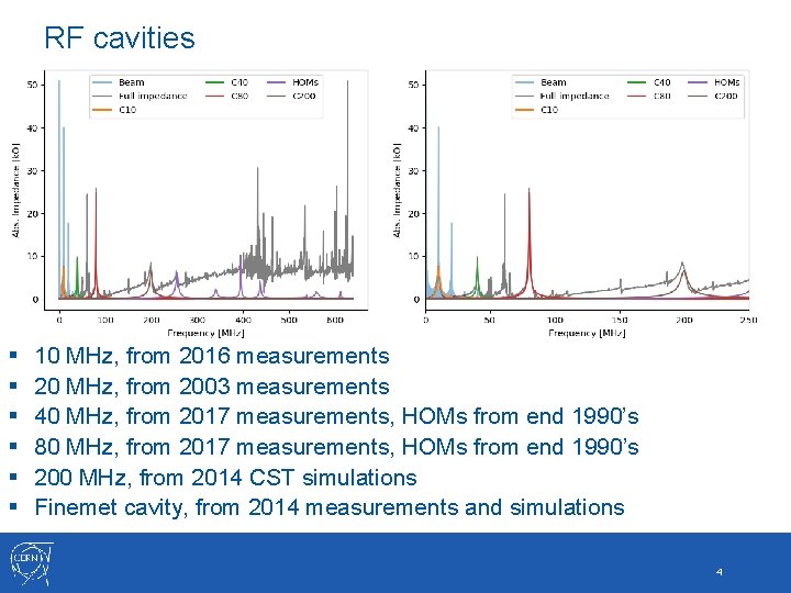
RF cavities § § § 10 MHz, from 2016 measurements 20 MHz, from 2003 measurements 40 MHz, from 2017 measurements, HOMs from end 1990’s 80 MHz, from 2017 measurements, HOMs from end 1990’s 200 MHz, from 2014 CST simulations Finemet cavity, from 2014 measurements and simulations 4
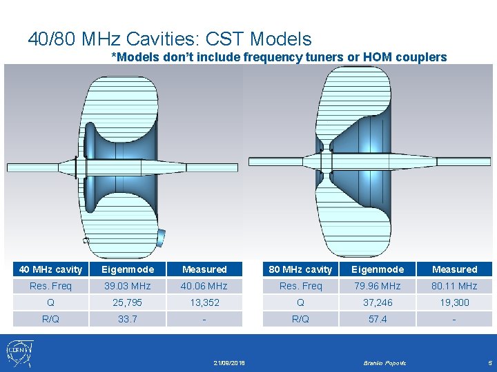
40/80 MHz Cavities: CST Models *Models don’t include frequency tuners or HOM couplers 40 MHz cavity Eigenmode Measured 80 MHz cavity Eigenmode Measured Res. Freq 39. 03 MHz 40. 06 MHz Res. Freq 79. 96 MHz 80. 11 MHz Q 25, 795 13, 352 Q 37, 246 19, 300 R/Q 33. 7 - R/Q 57. 4 - 21/09/2018 Branko Popovic 5
40/80 MHz Cavities: Model Summary • Shape of mechanical short is included • • • Does not include tuners that adjust frequency Does not include HOM dampers • • • Separate model of the mechanical short has been analyzed Explore how to implement this in Wakefield Simulations The impedance is dominated by the feedback Option proposed for dealing with the feedback • Obtain impedance of 80 MHz cavity using measurements of gap voltage instead of modeling the feedback loops 21/09/2018 Branko Popovic 6
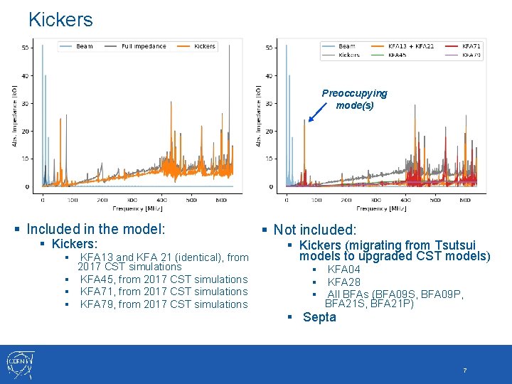
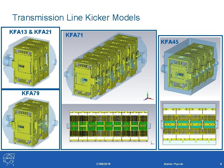
Kickers Preoccupying mode(s) § Included in the model: § Kickers: § KFA 13 and KFA 21 (identical), from 2017 CST simulations § KFA 45, from 2017 CST simulations § KFA 71, from 2017 CST simulations § KFA 79, from 2017 CST simulations § Not included: § Kickers (migrating from Tsutsui models to upgraded CST models) § KFA 04 § KFA 28 § All BFAs (BFA 09 S, BFA 09 P, BFA 21 S, BFA 21 P) § Septa 7
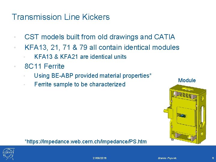
Transmission Line Kickers • • CST models built from old drawings and CATIA KFA 13, 21, 71 & 79 all contain identical modules • • KFA 13 & KFA 21 are identical units 8 C 11 Ferrite • • Using BE-ABP provided material properties* Ferrite sample to be characterized Module *https: //impedance. web. cern. ch/impedance/PS. htm 21/09/2018 Branko Popovic 8
Transmission Line Kicker Models KFA 13 & KFA 21 KFA 71 KFA 45 KFA 79 21/09/2018 Branko Popovic 9
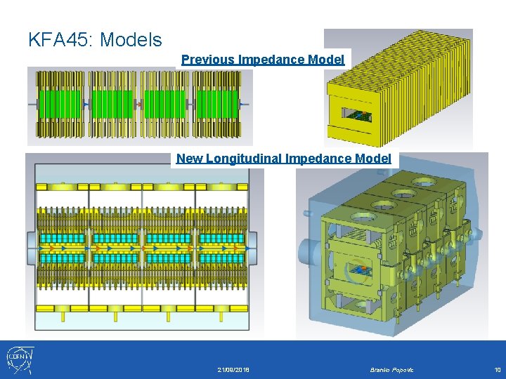
KFA 45: Models Previous Impedance Model New Longitudinal Impedance Model 21/09/2018 Branko Popovic 10
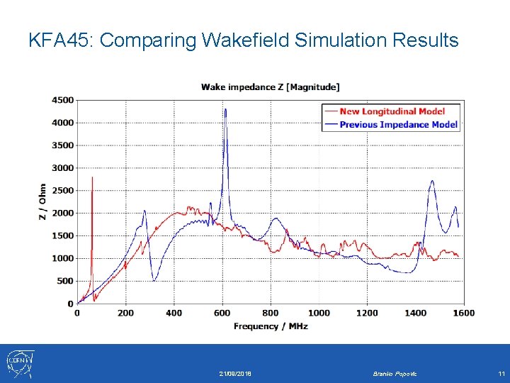
KFA 45: Comparing Wakefield Simulation Results 21/09/2018 Branko Popovic 11
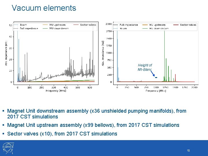
Vacuum elements Height of Mt-Blanc § Magnet Unit downstream assembly (x 36 unshielded pumping manifolds), from 2017 CST simulations § Magnet Unit upstream assembly (x 99 bellows), from 2017 CST simulations § Sector valves (x 10), from 2017 CST simulations 12
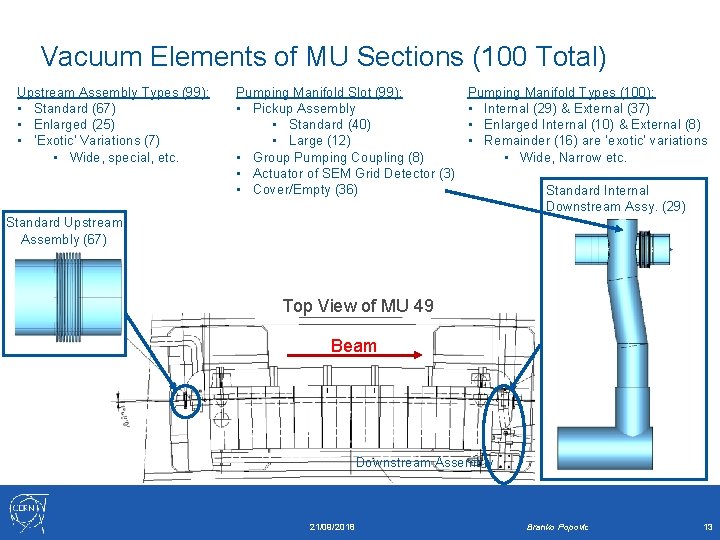
Vacuum Elements of MU Sections (100 Total) Upstream Assembly Types (99): • Standard (67) • Enlarged (25) • ‘Exotic’ Variations (7) • Wide, special, etc. Pumping Manifold Slot (99): • Pickup Assembly • Standard (40) • Large (12) • Group Pumping Coupling (8) • Actuator of SEM Grid Detector (3) • Cover/Empty (36) Pumping Manifold Types (100): • Internal (29) & External (37) • Enlarged Internal (10) & External (8) • Remainder (16) are ‘exotic’ variations • Wide, Narrow etc. Standard Internal Downstream Assy. (29) Standard Upstream Assembly (67) Top View of MU 49 Beam Downstream Assembly 21/09/2018 Branko Popovic 13
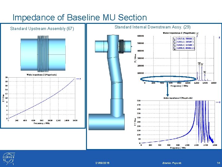
Impedance of Baseline MU Section Standard Internal Downstream Assy. (29) Standard Upstream Assembly (67) 21/09/2018 Branko Popovic 14
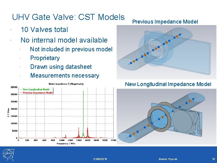
UHV Gate Valve: CST Models • • Previous Impedance Model 10 Valves total No internal model available • • Not included in previous model Proprietary Drawn using datasheet Measurements necessary New Longitudinal Impedance Model 21/09/2018 Branko Popovic 15
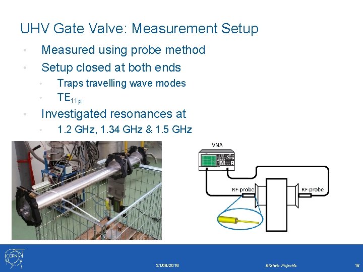
UHV Gate Valve: Measurement Setup • • Measured using probe method Setup closed at both ends • • • Traps travelling wave modes TE 11 p Investigated resonances at • 1. 2 GHz, 1. 34 GHz & 1. 5 GHz 21/09/2018 Branko Popovic 16
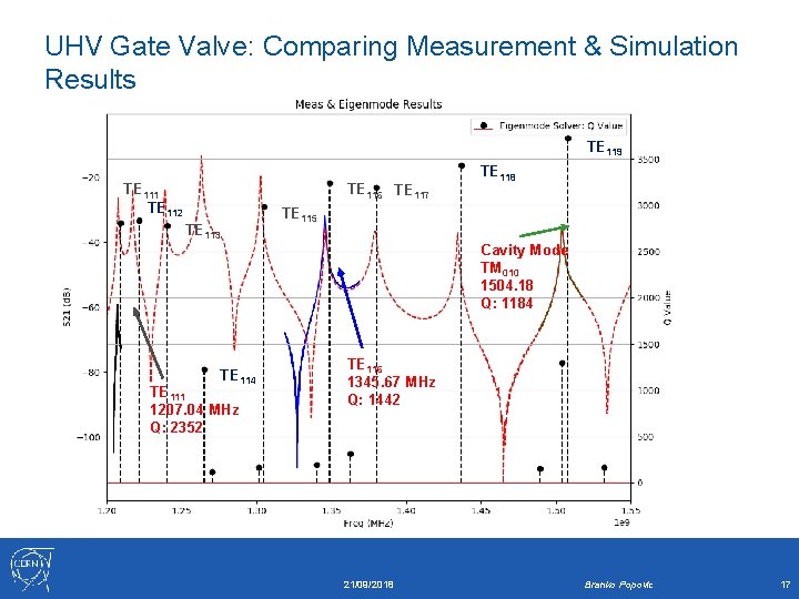
UHV Gate Valve: Comparing Measurement & Simulation Results TE 119 TE 111 TE 112 TE 116 TE 117 TE 113 TE 118 TE 115 Cavity Mode TM 010 1504. 18 Q: 1184 TE 111 1207. 04 MHz Q: 2352 TE 116 1345. 67 MHz Q: 1442 21/09/2018 Branko Popovic 17
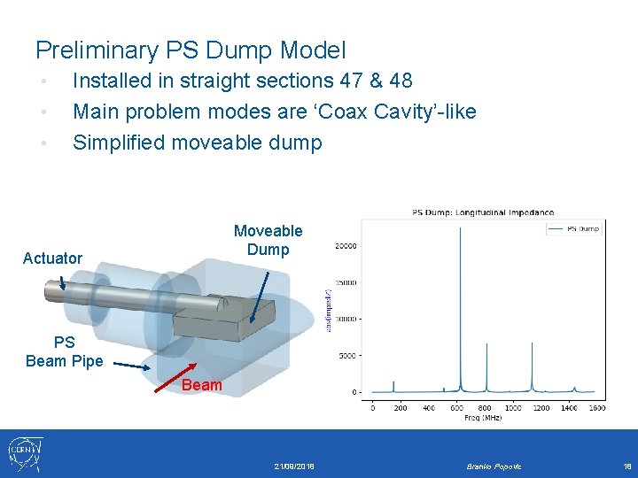
Preliminary PS Dump Model • • • Installed in straight sections 47 & 48 Main problem modes are ‘Coax Cavity’-like Simplified moveable dump Moveable Dump Actuator PS Beam Pipe Beam 21/09/2018 Branko Popovic 18
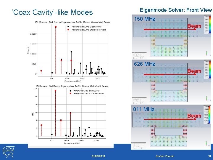
‘Coax Cavity’-like Modes Eigenmode Solver: Front View 150 MHz Beam 626 MHz Beam 811 MHz Beam 21/09/2018 Branko Popovic 19
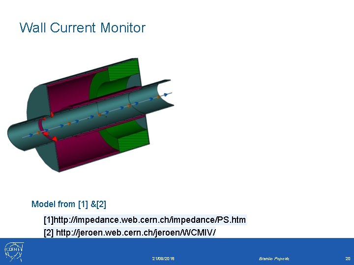
Wall Current Monitor Model from [1] &[2] [1]http: //impedance. web. cern. ch/impedance/PS. htm [2] http: //jeroen. web. cern. ch/jeroen/WCMIV/ 21/09/2018 Branko Popovic 20
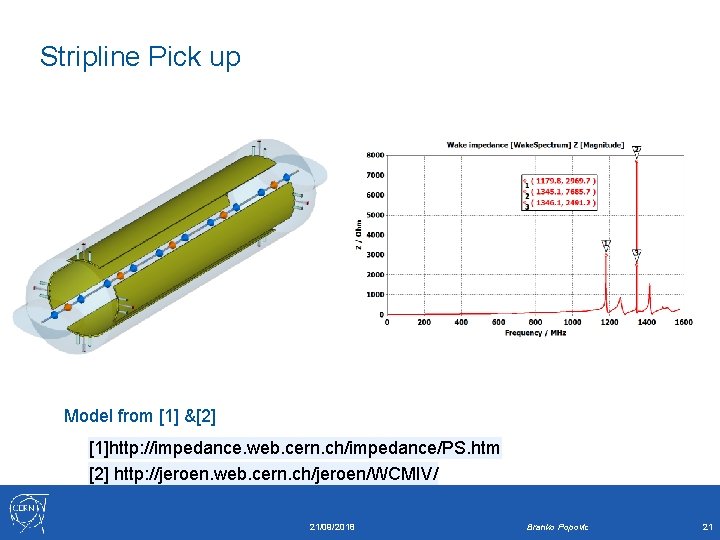
Stripline Pick up Model from [1] &[2] [1]http: //impedance. web. cern. ch/impedance/PS. htm [2] http: //jeroen. web. cern. ch/jeroen/WCMIV/ 21/09/2018 Branko Popovic 21
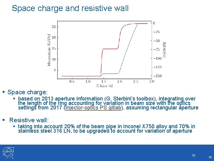
Space charge and resistive wall § Space charge: § based on 2013 aperture information (G. Sterbini’s toolbox), integrating over the length of the ring accounting for variation in beam size with the optics settings from 2017 (injector-optics PS gitlab), assuming rectangular aperture § Resistive wall: § taking into account 20% of the beam pipe in Inconel X 750 alloy and 70% in stainless steel 316 LN, to be upgraded to account for variation of aperture 22 22
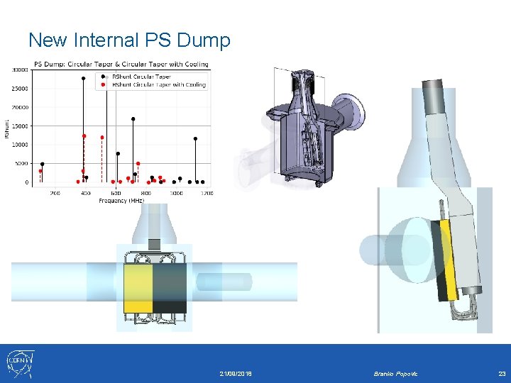
New Internal PS Dump 21/09/2018 Branko Popovic 23
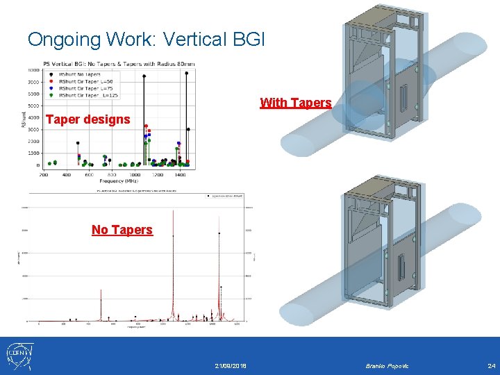
Ongoing Work: Vertical BGI With Tapers Taper designs No Tapers 21/09/2018 Branko Popovic 24
Path Forward • BI Equipment • • • Wire scanners Septums Straight (SD) & Magnet (MU) Sections • CODD model in progress 21/09/2018 Branko Popovic 25
Further Elements to add • • Complete survey of straight sections (SD) 20 MHz & 200 MHz Cavities Septums Remaining Kickers • • Beam instrumentation • • KFA 4 & KFA 28 Wall current monitors Wire scanners Pick-ups Vacuum elements • Flanges, bellows, transitions 21/09/2018 Branko Popovic 26
Summary 1. Cavities are most obvious candidates for intensity effects • • 2. Main source of broadband impedance • 3. Kickers’ resonances at low frequency Future elements need to be analyzed & reduced when possible • 4. Large R-Shunt values Reduction via feedbacks Example: New beam dump design Multiple sources of high frequency impedance with large impedance (risk of microwave instability) • • Gate valves Pumping manifolds in magnet unit (MU) sections 21/09/2018 Branko Popovic 27
Supplemental Slides 21/09/2018 Branko Popovic 28
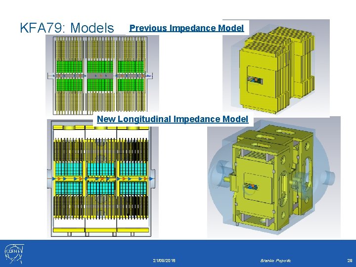
KFA 79: Models Previous Impedance Model New Longitudinal Impedance Model 21/09/2018 Branko Popovic 29
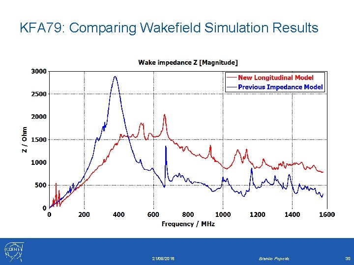
KFA 79: Comparing Wakefield Simulation Results 21/09/2018 Branko Popovic 30
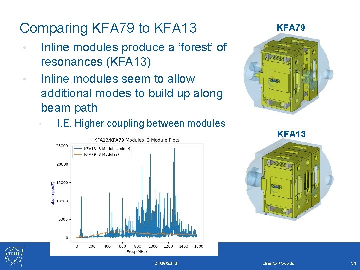
Comparing KFA 79 to KFA 13 • • KFA 79 Inline modules produce a ‘forest’ of resonances (KFA 13) Inline modules seem to allow additional modes to build up along beam path • I. E. Higher coupling between modules KFA 13 21/09/2018 Branko Popovic 31
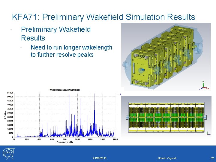
KFA 71: Preliminary Wakefield Simulation Results • Preliminary Wakefield Results • Need to run longer wakelength to further resolve peaks 21/09/2018 Branko Popovic 32
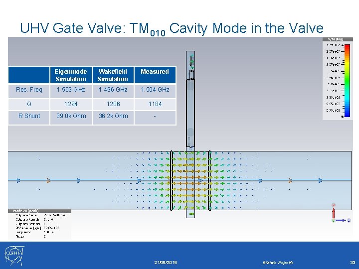
UHV Gate Valve: TM 010 Cavity Mode in the Valve Eigenmode Simulation Wakefield Simulation Measured Res. Freq 1. 503 GHz 1. 496 GHz 1. 504 GHz Q 1294 1206 1184 R Shunt 39. 0 k Ohm 36. 2 k Ohm - 21/09/2018 Branko Popovic 33
- Slides: 33