
PRT 101 Introduction to Process Technology Chapter 5








- Slides: 153
PRT 101 Introduction to Process Technology Chapter 5 – Process variables, Elements, & instruments: Flow
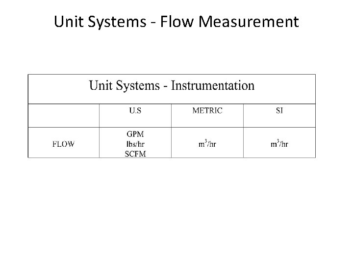
Unit Systems - Flow Measurement
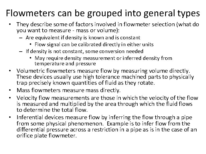
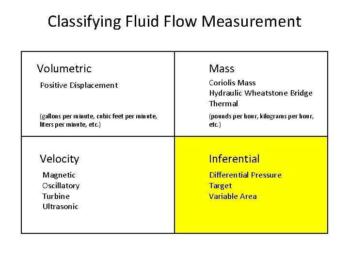
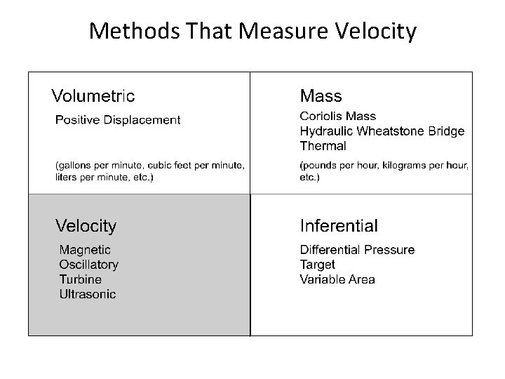
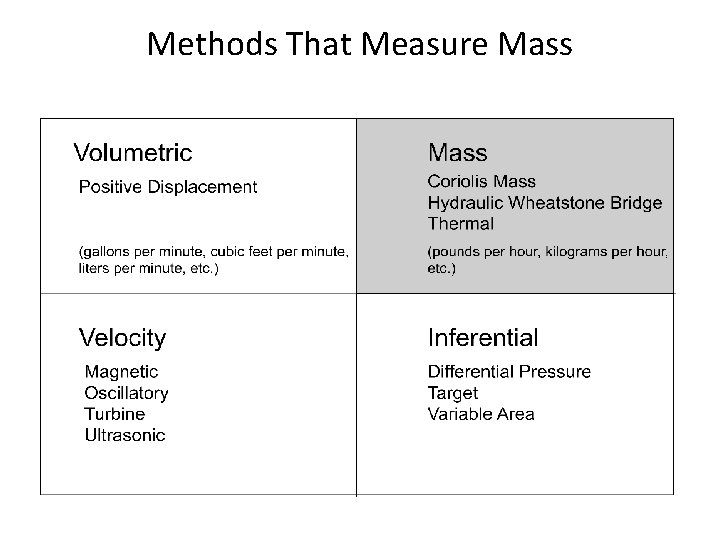
Flowmeters can be grouped into general types • They describe some of factors involved in flowmeter selection (what do you want to measure - mass or volume): – Are equivalent if density is known and is constant • Flow signal can be calibrated directly in either units – If density is not constant, some conversion needed • May require density measurement or inferred density from temperature and pressure • Volumetric flowmeters measure flow by measuring volume directly. These devices usually use high tolerance machined parts to physically trap precisely known quantities of fluid as they rotate. • Mass flowmeters measure mass directly. • Velocity flow measurements are those in which the velocity of the flow is measured and multiplied by the area through which the fluid flows to determine the total flow. • Inferential devices measure flow by inferring the flow through a pipe from some physical phenomenon. Example is to infer flow from the differential pressure across a restriction in a pipe as is in the case of an orifice plate flowmeter.
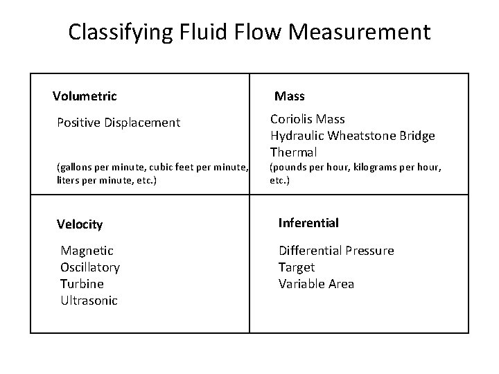
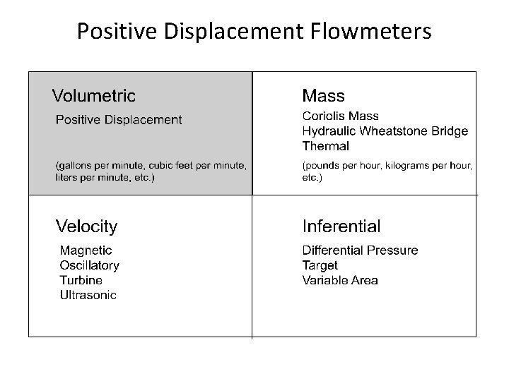
Classifying Fluid Flow Measurement Volumetric Mass Positive Displacement Coriolis Mass Hydraulic Wheatstone Bridge Thermal (gallons per minute, cubic feet per minute, liters per minute, etc. ) (pounds per hour, kilograms per hour, etc. ) Velocity Inferential Magnetic Oscillatory Turbine Ultrasonic Differential Pressure Target Variable Area
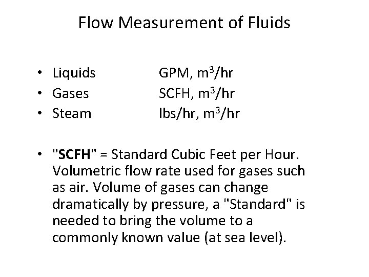
Flow Measurement of Fluids • Liquids • Gases • Steam GPM, m 3/hr SCFH, m 3/hr lbs/hr, m 3/hr • "SCFH" = Standard Cubic Feet per Hour. Volumetric flow rate used for gases such as air. Volume of gases can change dramatically by pressure, a "Standard" is needed to bring the volume to a commonly known value (at sea level).
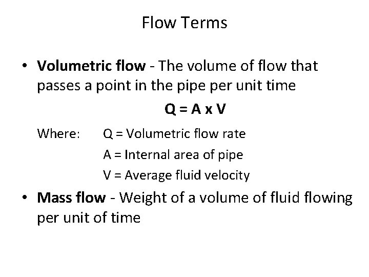
Flow Terms • Volumetric flow - The volume of flow that passes a point in the pipe per unit time Q = A x V Where: Q = Volumetric flow rate A = Internal area of pipe V = Average fluid velocity • Mass flow - Weight of a volume of fluid flowing per unit of time
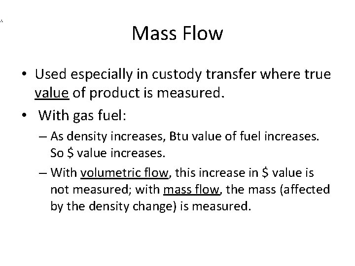
Mass Flow • Used especially in custody transfer where true value of product is measured. • With gas fuel: – As density increases, Btu value of fuel increases. So $ value increases. – With volumetric flow, this increase in $ value is not measured; with mass flow, the mass (affected by the density change) is measured.
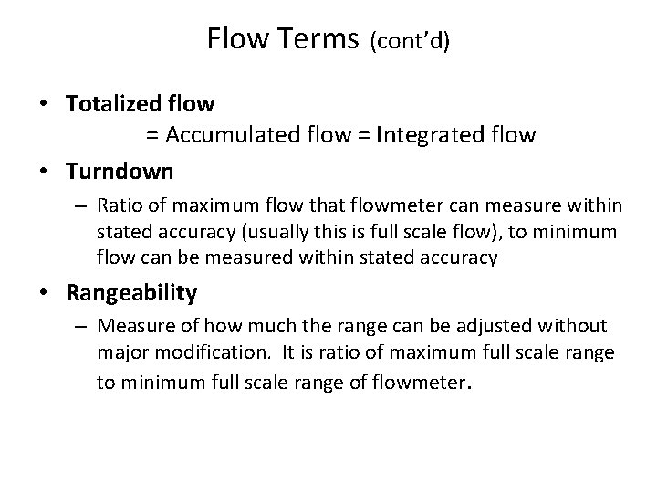
Flow Terms (cont’d) • Totalized flow = Accumulated flow = Integrated flow • Turndown – Ratio of maximum flow that flowmeter can measure within stated accuracy (usually this is full scale flow), to minimum flow can be measured within stated accuracy • Rangeability – Measure of how much the range can be adjusted without major modification. It is ratio of maximum full scale range to minimum full scale range of flowmeter.
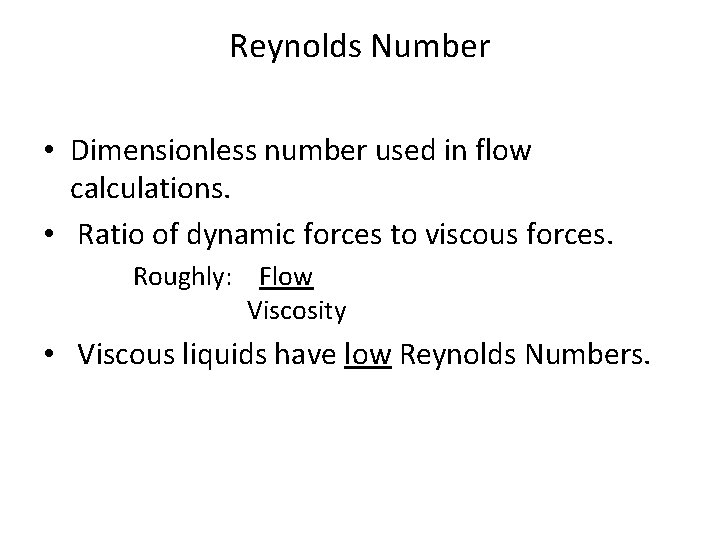
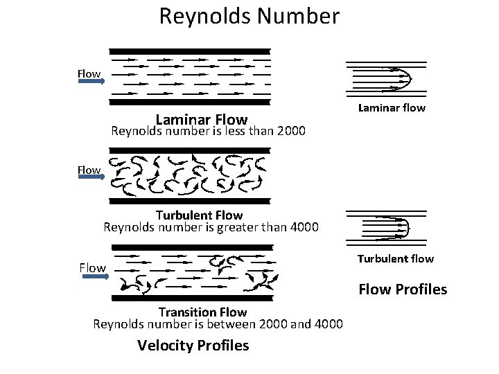
Reynolds Number • Dimensionless number used in flow calculations. • Ratio of dynamic forces to viscous forces. Roughly: Flow Viscosity • Viscous liquids have low Reynolds Numbers.
Reynolds Number Flow Laminar flow Reynolds number is less than 2000 Flow Turbulent Flow Reynolds number is greater than 4000 Turbulent flow Flow Profiles Transition Flow Reynolds number is between 2000 and 4000 Velocity Profiles
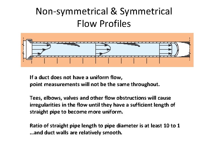
Non-symmetrical & Symmetrical Flow Profiles If a duct does not have a uniform flow, point measurements will not be the same throughout. Tees, elbows, valves and other flow obstructions will cause irregularities in the flow until they have a sufficient length of straight pipe to become more uniform. Ratio of straight pipe length to pipe diameter is at least 10 to 1 …and duct walls are relatively smooth.
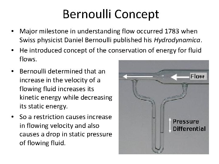
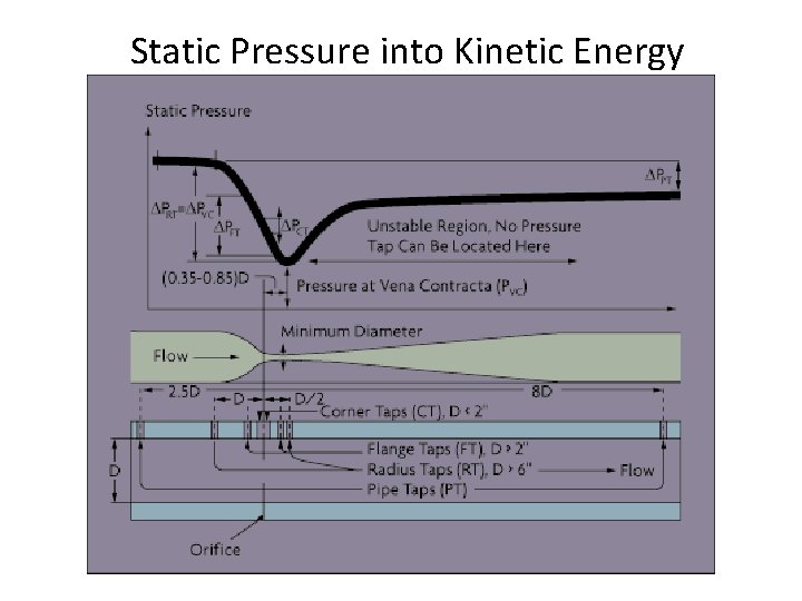
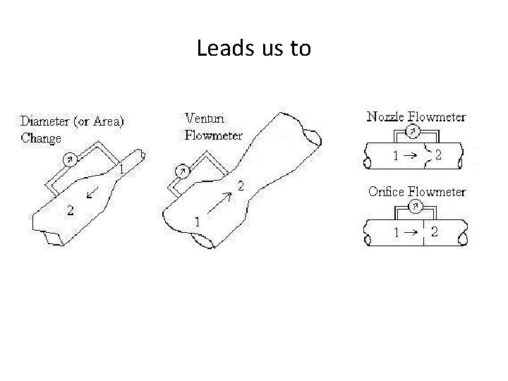
Bernoulli Concept • Major milestone in understanding flow occurred 1783 when Swiss physicist Daniel Bernoulli published his Hydrodynamica. • He introduced concept of the conservation of energy for fluid flows. • Bernoulli determined that an increase in the velocity of a flowing fluid increases its kinetic energy while decreasing its static energy. • So a restriction causes increase in flowing velocity and also causes a drop in static pressure of flowing fluid.
Static Pressure into Kinetic Energy
Leads us to
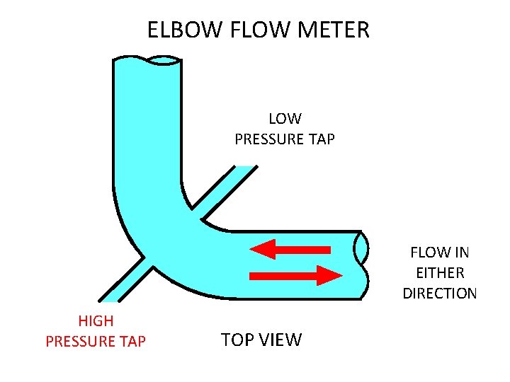
ELBOW FLOW METER LOW PRESSURE TAP FLOW IN EITHER DIRECTION HIGH PRESSURE TAP TOP VIEW Fig 5 -7
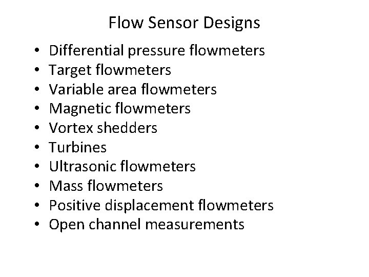
Flow Sensor Designs • • • Differential pressure flowmeters Target flowmeters Variable area flowmeters Magnetic flowmeters Vortex shedders Turbines Ultrasonic flowmeters Mass flowmeters Positive displacement flowmeters Open channel measurements
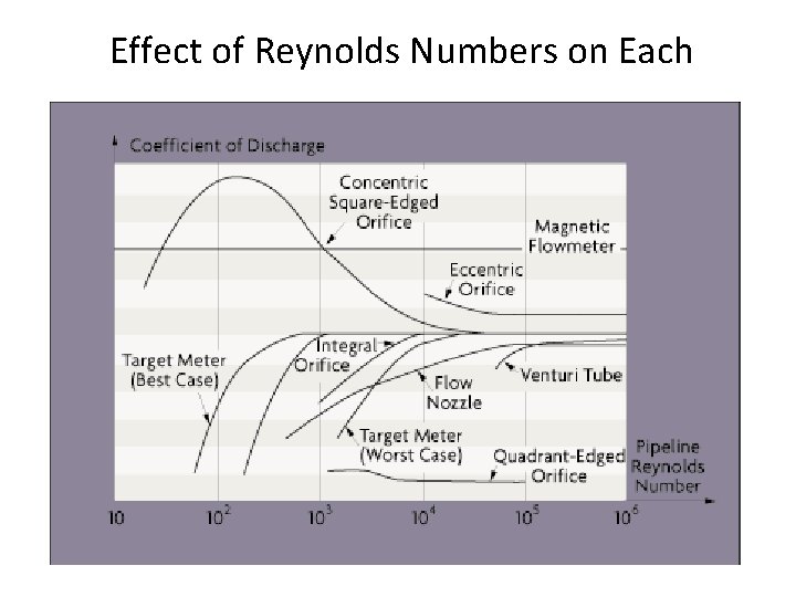
Effect of Reynolds Numbers on Each
Classifying Fluid Flow Measurement Volumetric Mass Positive Displacement Coriolis Mass Hydraulic Wheatstone Bridge Thermal (gallons per minute, cubic feet per minute, liters per minute, etc. ) (pounds per hour, kilograms per hour, etc. ) Velocity Inferential Magnetic Oscillatory Turbine Ultrasonic Differential Pressure Target Variable Area
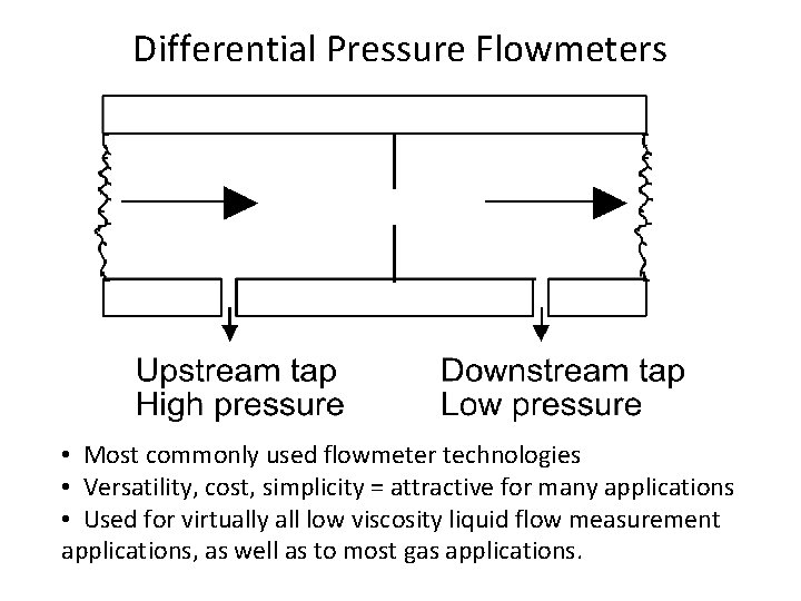
Differential Pressure Flowmeters • Most commonly used flowmeter technologies • Versatility, cost, simplicity = attractive for many applications • Used for virtually all low viscosity liquid flow measurement applications, as well as to most gas applications.
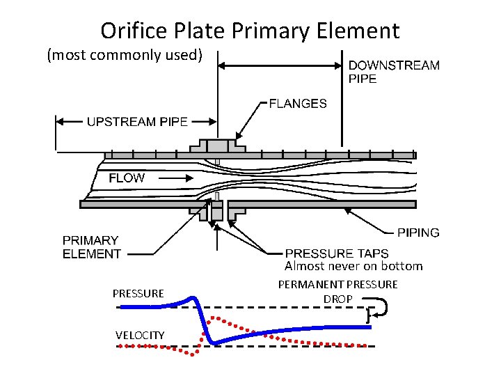
Orifice Plate Primary Element (most commonly used) Almost never on bottom PRESSURE VELOCITY PERMANENT PRESSURE DROP
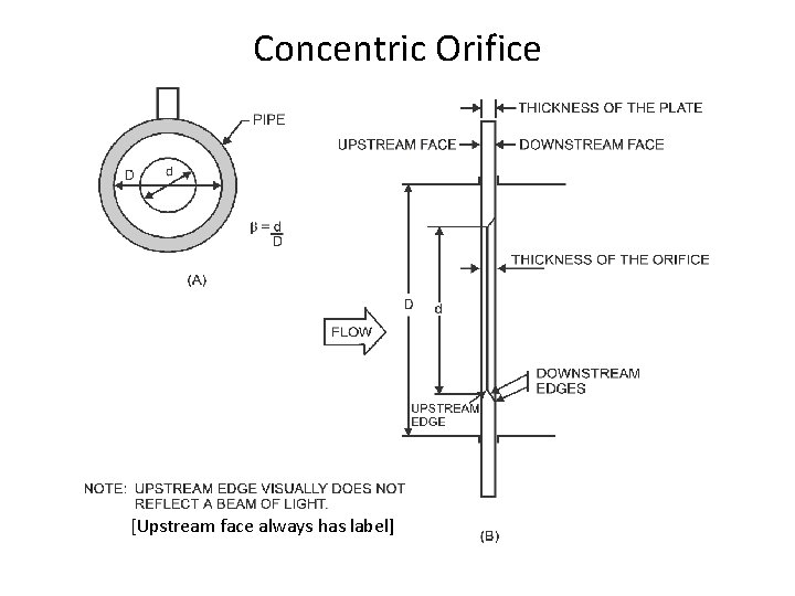
Concentric Orifice [Upstream face always has label]
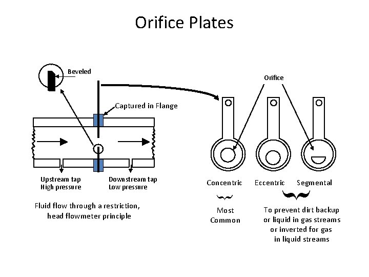
Orifice Plates Beveled Orifice Captured in Flange Downstream tap Low pressure Fluid flow through a restriction, head flowmeter principle Concentric Most Common Eccentric Segmental Upstream tap High pressure To prevent dirt backup or liquid in gas streams or inverted for gas in liquid streams
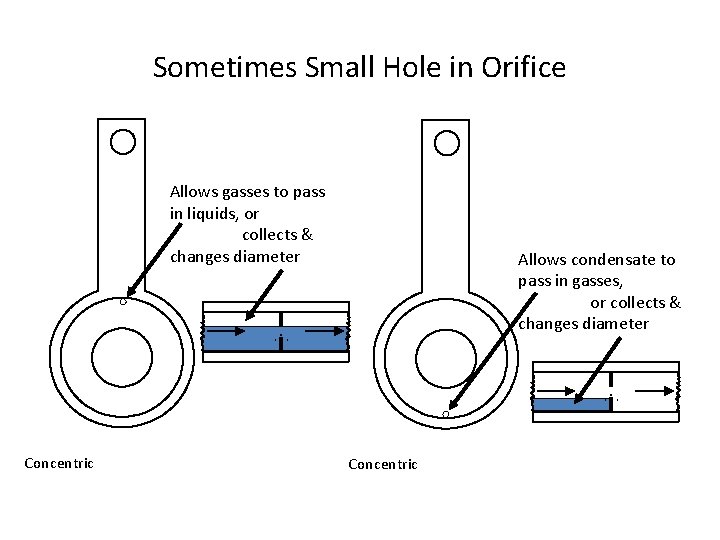
Sometimes Small Hole in Orifice Allows gasses to pass in liquids, or collects & changes diameter Concentric Allows condensate to pass in gasses, or collects & changes diameter Concentric
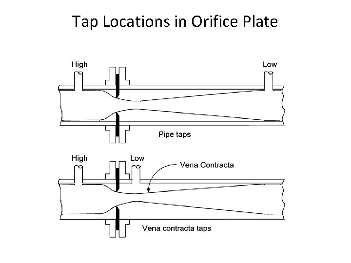
Tap Locations in Orifice Plate
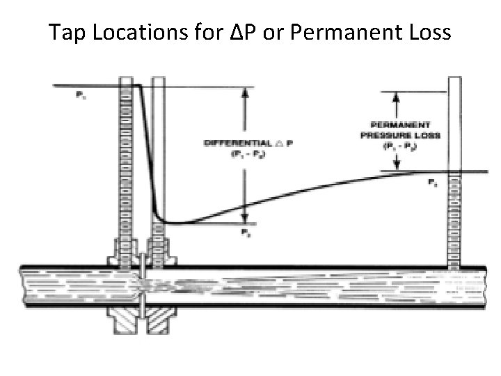
Tap Locations for ΔP or Permanent Loss
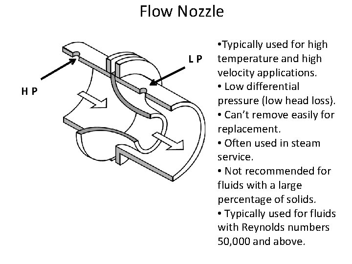
Flow Nozzle L P H P • Typically used for high temperature and high velocity applications. • Low differential pressure (low head loss). • Can’t remove easily for replacement. • Often used in steam service. • Not recommended for fluids with a large percentage of solids. • Typically used for fluids with Reynolds numbers 50, 000 and above.
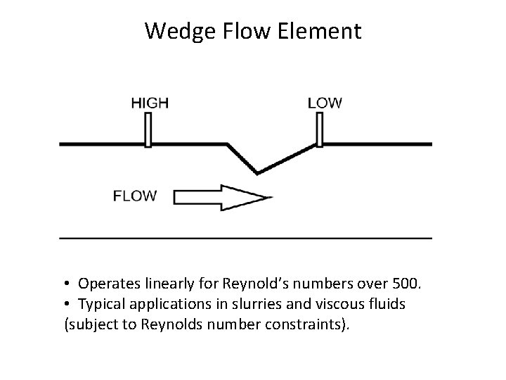
Wedge Flow Element • Operates linearly for Reynold’s numbers over 500. • Typical applications in slurries and viscous fluids (subject to Reynolds number constraints).
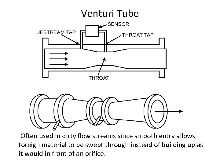
Venturi Tube Often used in dirty flow streams since smooth entry allows foreign material to be swept through instead of building up as it would in front of an orifice.
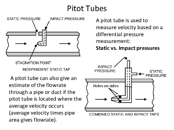
Pitot Tubes A pitot tube is used to measure velocity based on a differential pressure measurement: Static vs. Impact pressures A pitot tube can also give an estimate of the flowrate through a pipe or duct if the pitot tube is located where the average velocity occurs (average velocity times pipe area gives flowrate). Holes on sides
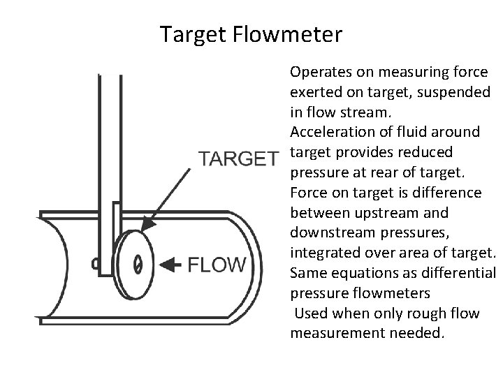
Target Flowmeter Operates on measuring force exerted on target, suspended in flow stream. Acceleration of fluid around target provides reduced pressure at rear of target. Force on target is difference between upstream and downstream pressures, integrated over area of target. Same equations as differential pressure flowmeters Used when only rough flow measurement needed.
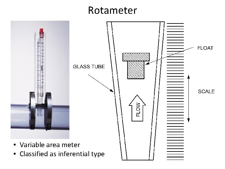
Rotameter • Variable area meter • Classified as inferential type
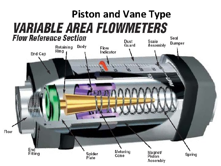
Piston and Vane Type
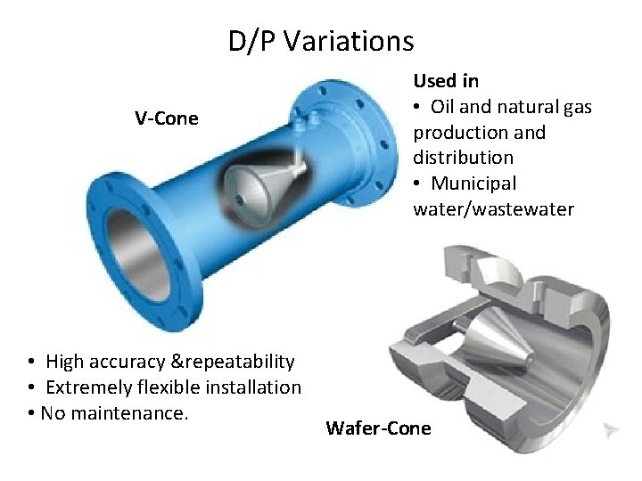
D/P Variations V-Cone • High accuracy &repeatability • Extremely flexible installation • No maintenance. Used in • Oil and natural gas production and distribution • Municipal water/wastewater Wafer-Cone
Methods That Measure Velocity
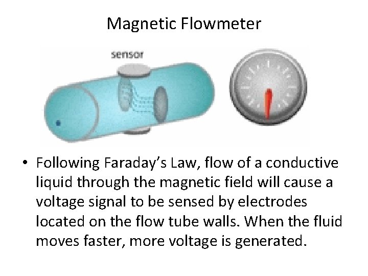
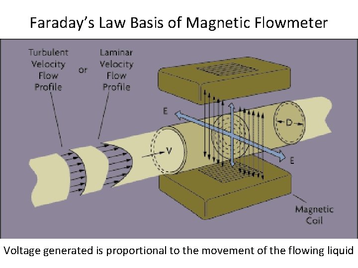
Magnetic Flowmeter • Following Faraday’s Law, flow of a conductive liquid through the magnetic field will cause a voltage signal to be sensed by electrodes located on the flow tube walls. When the fluid moves faster, more voltage is generated.
Faraday’s Law Basis of Magnetic Flowmeter Voltage generated is proportional to the movement of the flowing liquid
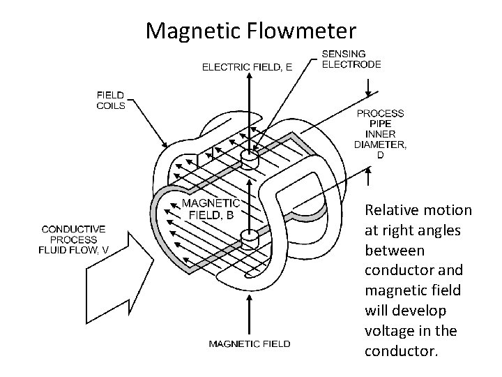
Magnetic Flowmeter Relative motion at right angles between conductor and magnetic field will develop voltage in the conductor.
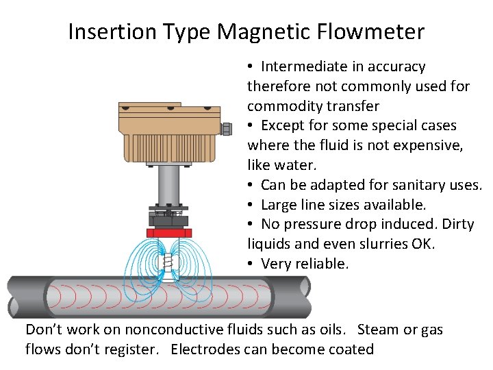
Insertion Type Magnetic Flowmeter • Intermediate in accuracy therefore not commonly used for commodity transfer • Except for some special cases where the fluid is not expensive, like water. • Can be adapted for sanitary uses. • Large line sizes available. • No pressure drop induced. Dirty liquids and even slurries OK. • Very reliable. Don’t work on nonconductive fluids such as oils. Steam or gas flows don’t register. Electrodes can become coated
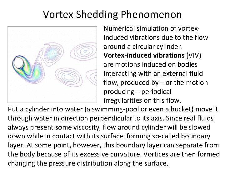
Vortex Shedding Phenomenon Numerical simulation of vortexinduced vibrations due to the flow around a circular cylinder. Vortex-induced vibrations (VIV) are motions induced on bodies interacting with an external fluid flow, produced by – or the motion producing – periodical irregularities on this flow. Put a cylinder into water (a swimming-pool or even a bucket) move it through water in direction perpendicular to its axis. Since real fluids always present some viscosity, flow around cylinder will be slowed down while in contact with its surface, forming so-called boundary layer. At some point, however, this boundary layer can separate from the body because of its excessive curvature. Vortices are then formed changing the pressure distribution along the surface.
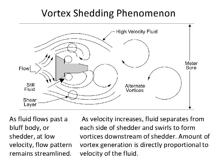
Vortex Shedding Phenomenon As fluid flows past a bluff body, or shedder, at low velocity, flow pattern remains streamlined. As velocity increases, fluid separates from each side of shedder and swirls to form vortices downstream of shedder. Amount of vortex generation is directly proportional to velocity of the fluid.
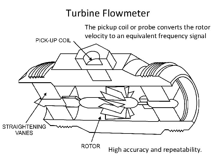
Turbine Flowmeter The pickup coil or probe converts the rotor velocity to an equivalent frequency signal High accuracy and repeatability.
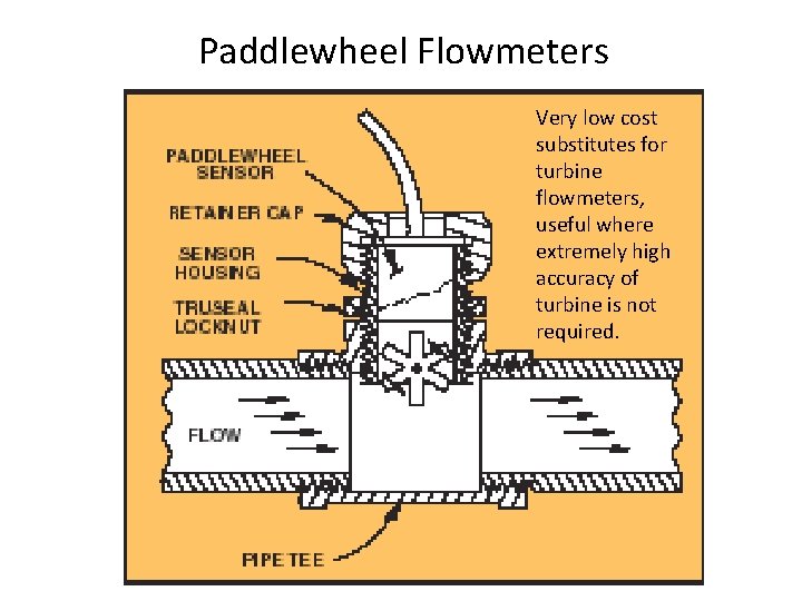
Paddlewheel Flowmeters Very low cost substitutes for turbine flowmeters, useful where extremely high accuracy of turbine is not required.
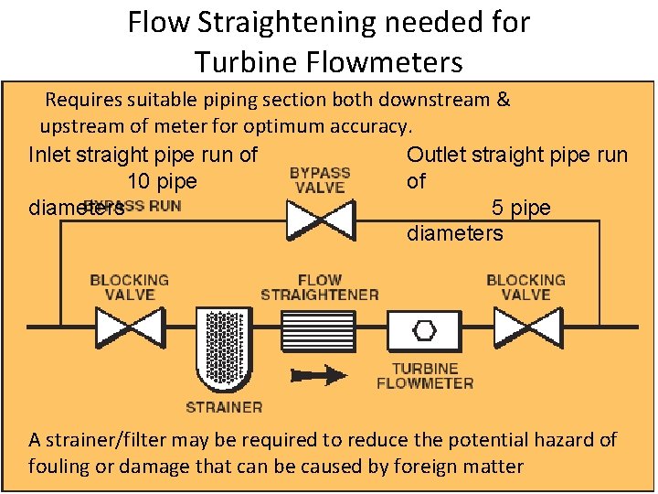
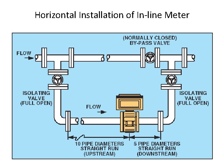
Flow Straightening needed for Turbine Flowmeters Requires suitable piping section both downstream & upstream of meter for optimum accuracy. Inlet straight pipe run of Outlet straight pipe run 10 pipe of diameters 5 pipe diameters A strainer/filter may be required to reduce the potential hazard of fouling or damage that can be caused by foreign matter
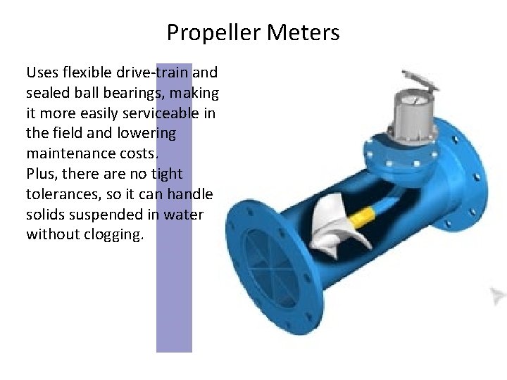
Propeller Meters Uses flexible drive-train and sealed ball bearings, making it more easily serviceable in the field and lowering maintenance costs. Plus, there are no tight tolerances, so it can handle solids suspended in water without clogging.
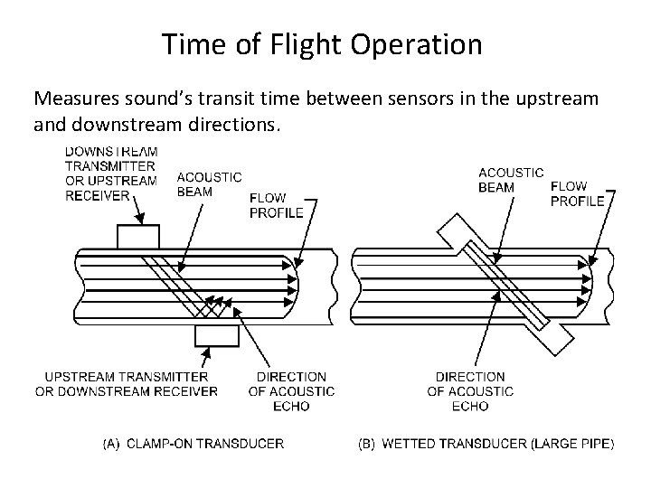
Ultrasonic Flowmeter Principles • Principle of operation – Doppler – Time of flight • Construction – Clamp-on transducer – Wetted transducer • Applications – – – Large pipes (cost) Flashing fluids Corrosive fluids Hazardous fluids Non-coating service
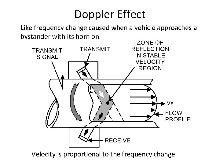
Doppler Effect Like frequency change caused when a vehicle approaches a bystander with its horn on. Velocity is proportional to the frequency change
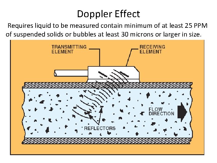
Doppler Effect Requires liquid to be measured contain minimum of at least 25 PPM of suspended solids or bubbles at least 30 microns or larger in size.
Doppler Effect • Requires liquid contain minimum of at least 25 PPM of suspended solids or bubbles at least 30 microns or larger in size. • Transducer frequency for these requirements is 1 megahertz. Lower frequencies require more PPM and a larger micron size. Until recently, 25 PPM of suspended solids or bubbles of at least 30 microns or larger, constituted the cleanest measurable application.
Newer Doppler Meters • Newer ultrasonic flowmeters have bridged gap towards use of cleaner liquid applications. Requiring no solids or entrained gas, this type of flowmeter can work on applications typical ultrasonic Doppler meter cannot measure. • Principles of operation are similar, with exception that Doppler signal is reflected by turbulent swirls in the liquid rather than by solid particles or bubbles. • Because of this, they can be used where there are no suspended solids or bubbles in the fluid. • The unit is specially calibrated must be installed one to three pipe diameters downstream of a 90° elbow. .
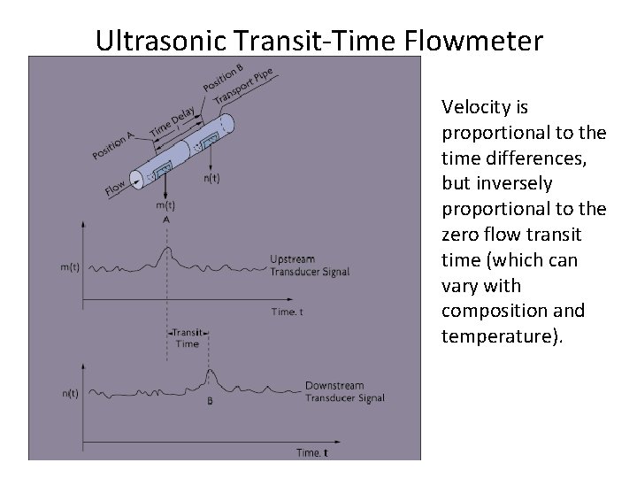
Time of Flight Operation Measures sound’s transit time between sensors in the upstream and downstream directions.
Ultrasonic Transit-Time Flowmeter Velocity is proportional to the time differences, but inversely proportional to the zero flow transit time (which can vary with composition and temperature).
Methods That Measure Mass
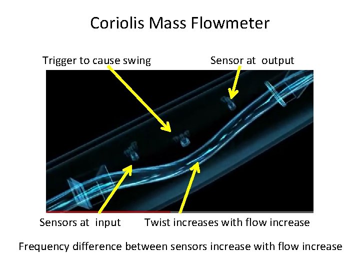
Coriolis Mass Flowmeter
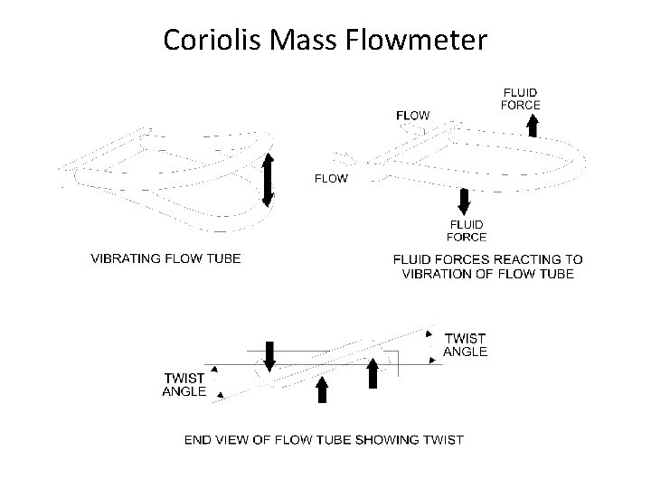
Coriolis Mass Flowmeter Trigger to cause swing Sensors at input Sensor at output Twist increases with flow increase Frequency difference between sensors increase with flow increase
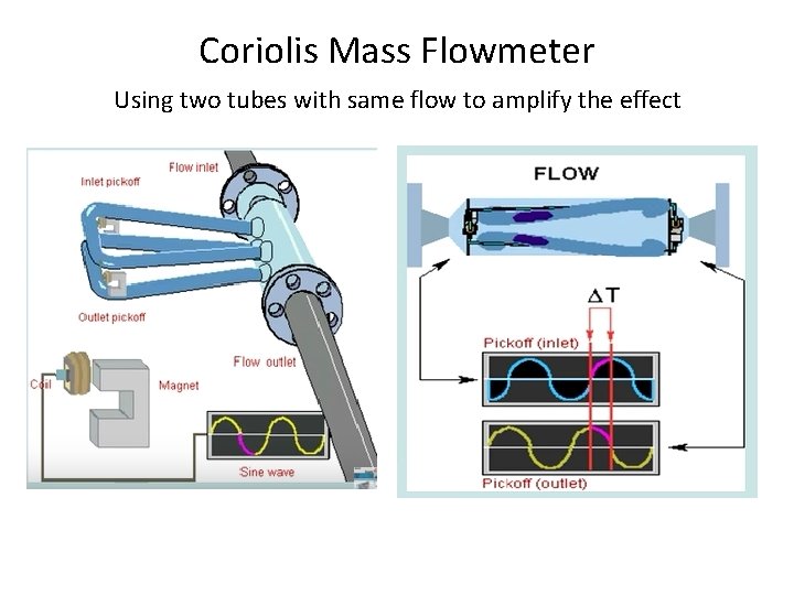
Coriolis Mass Flowmeter Using two tubes with same flow to amplify the effect
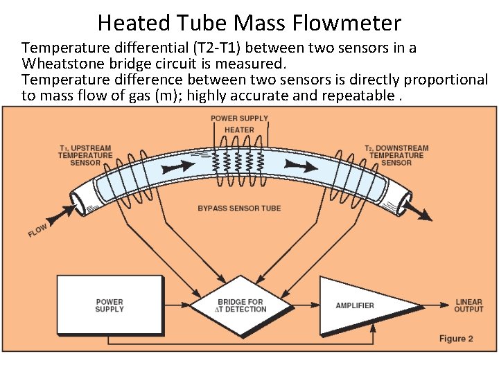
Heated Tube Mass Flowmeter Temperature differential (T 2 -T 1) between two sensors in a Wheatstone bridge circuit is measured. Temperature difference between two sensors is directly proportional to mass flow of gas (m); highly accurate and repeatable.
Positive Displacement Flowmeters
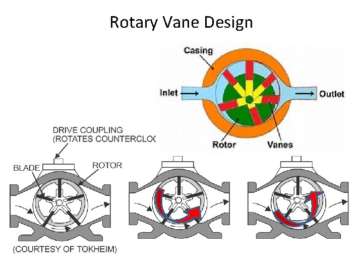
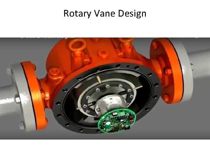
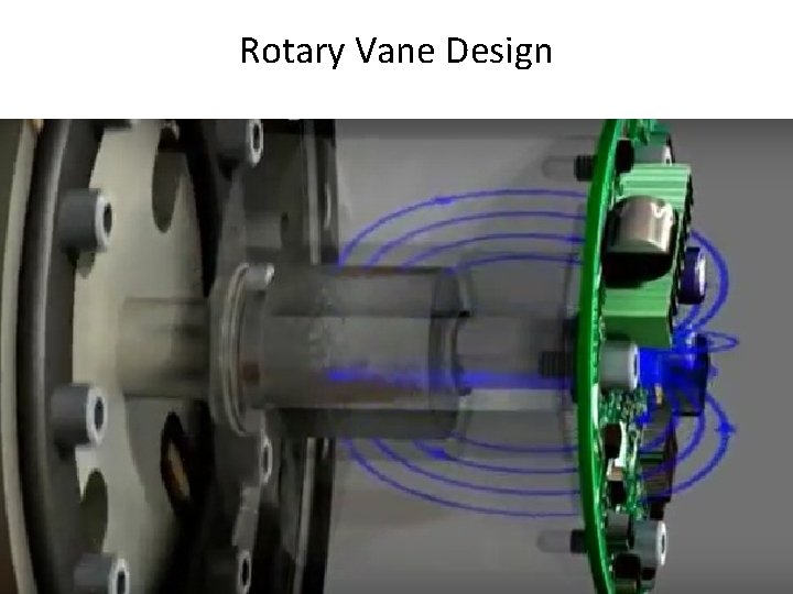
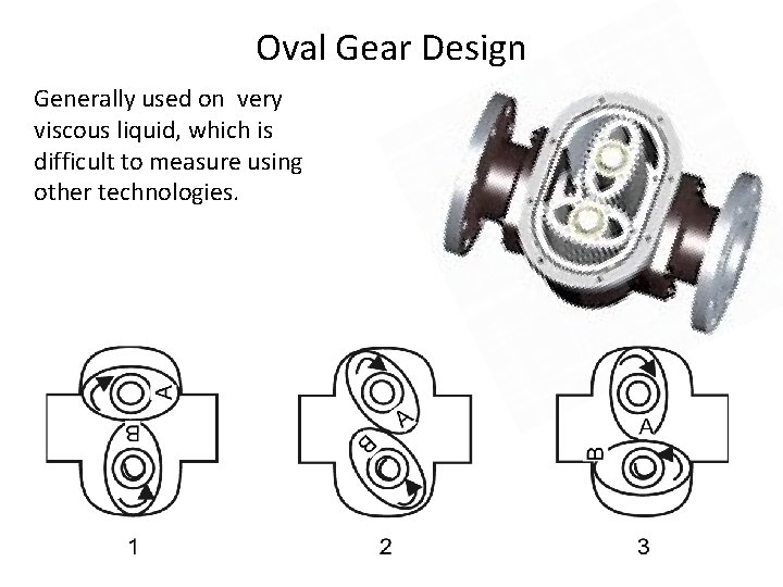
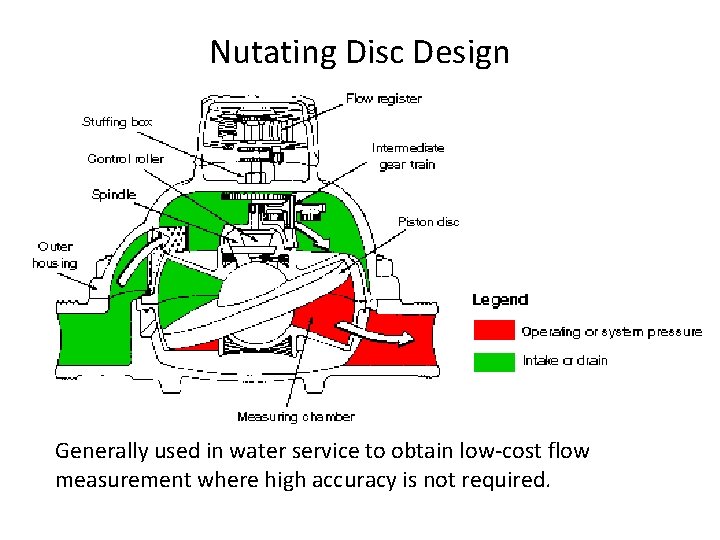
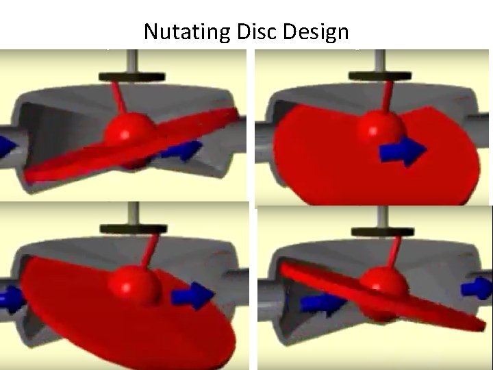
Positive Displacement Flowmeters • Positive-displacement flowmeters continuously entrap known quantity of fluid as it passes through meter. • Since number of times fluid is entrapped and volume of entrapped fluid are known, amount of fluid that has passed through meter is easily determined. • Three common types of positive displacement flowmeters encountered in process control will be briefly discussed. – Rotary vane – Oval gear – Nutating disk
Rotary Vane Design
Rotary Vane Design
Rotary Vane Design
Oval Gear Design Generally used on very viscous liquid, which is difficult to measure using other technologies.
Nutating Disc Design Generally used in water service to obtain low-cost flow measurement where high accuracy is not required.
Nutating Disc Design
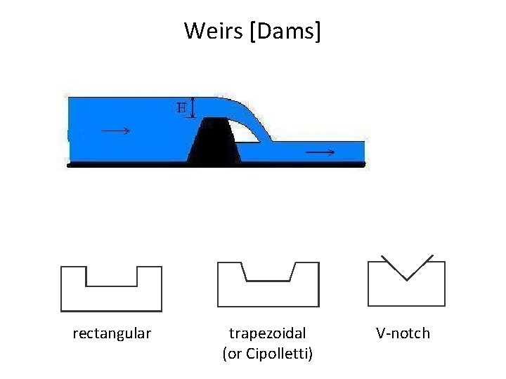
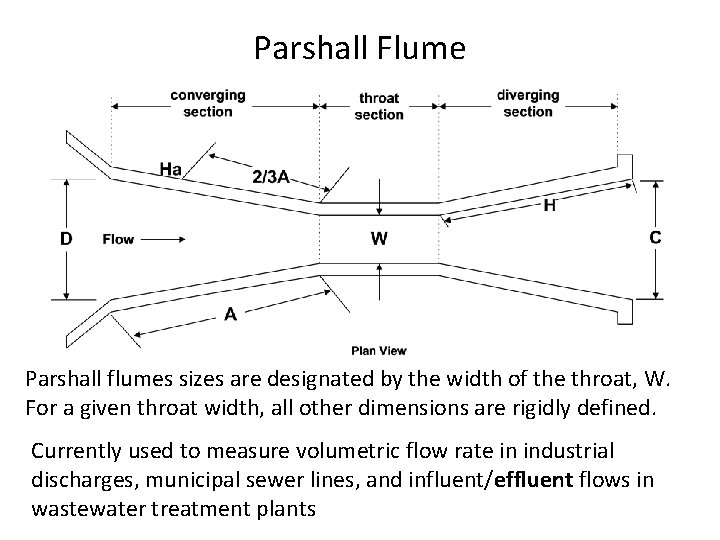
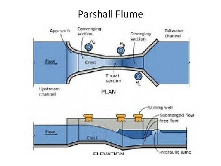
Open Channel Flow Measurement • • Weir Flume Require level measurement Usually used for large flows – Waste treatment – Rivers and streams
Weirs [Dams] rectangular trapezoidal (or Cipolletti) V-notch
Parshall Flume Parshall flumes sizes are designated by the width of the throat, W. For a given throat width, all other dimensions are rigidly defined. Currently used to measure volumetric flow rate in industrial discharges, municipal sewer lines, and influent/effluent flows in wastewater treatment plants
Parshall Flume
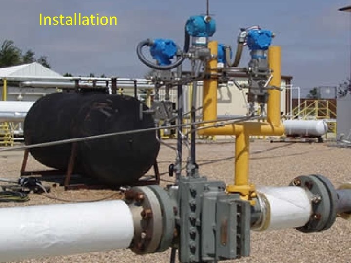
Installation
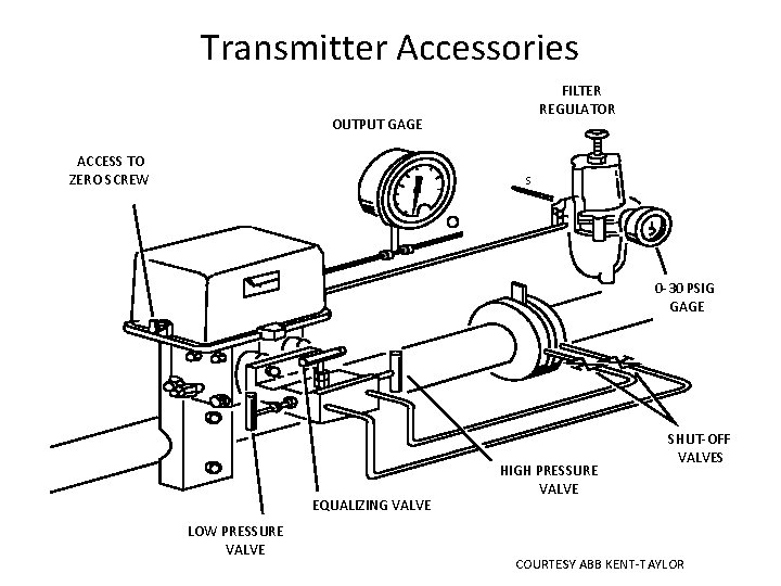
Transmitter Accessories FILTER REGULATOR OUTPUT GAGE ACCESS TO ZERO SCREW S 0 -30 PSIG GAGE EQUALIZING VALVE LOW PRESSURE VALVE HIGH PRESSURE VALVE SHUT-OFF VALVES COURTESY ABB KENT-TAYLOR
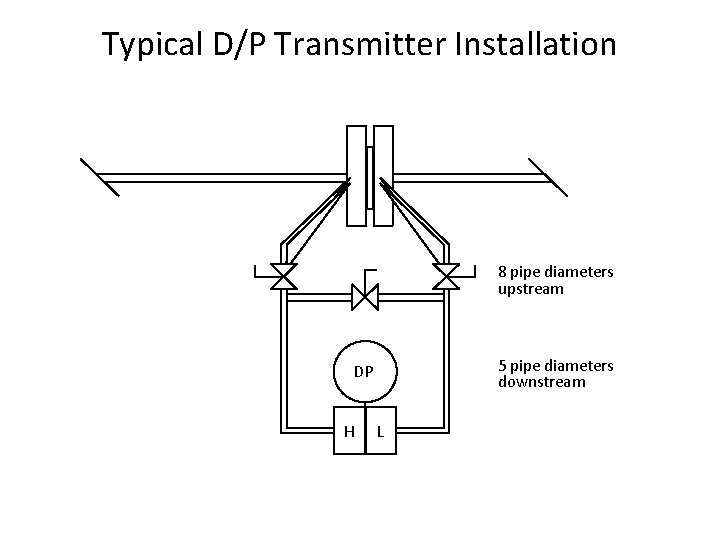
Typical D/P Transmitter Installation 8 pipe diameters upstream 5 pipe diameters downstream DP H L
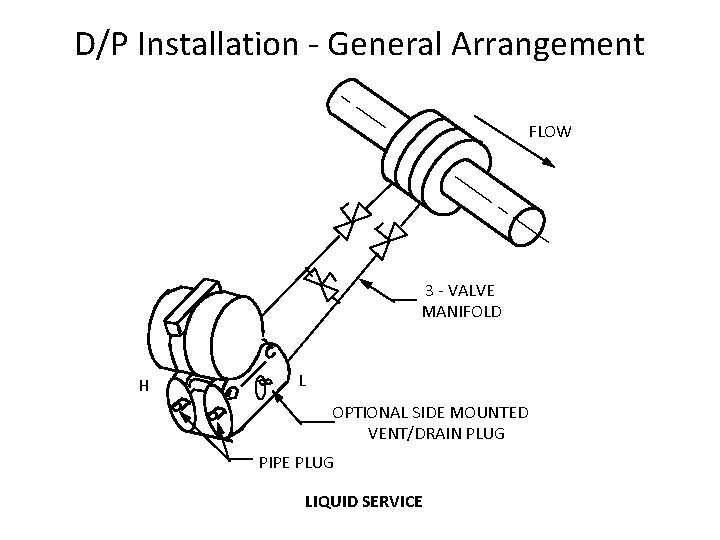
D/P Installation - General Arrangement FLOW 3 - VALVE MANIFOLD H L OPTIONAL SIDE MOUNTED VENT/DRAIN PLUG PIPE PLUG LIQUID SERVICE
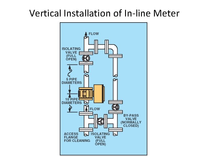
Vertical Installation of In-line Meter
Horizontal Installation of In-line Meter
Summary: Flow Instrumentation • • • Differential pressure flowmeters Target flowmeters Variable area flowmeters Magnetic flowmeters Vortex shedders Turbines Ultrasonic flowmeters Mass flowmeters Positive displacement flowmeters Open channel measurements
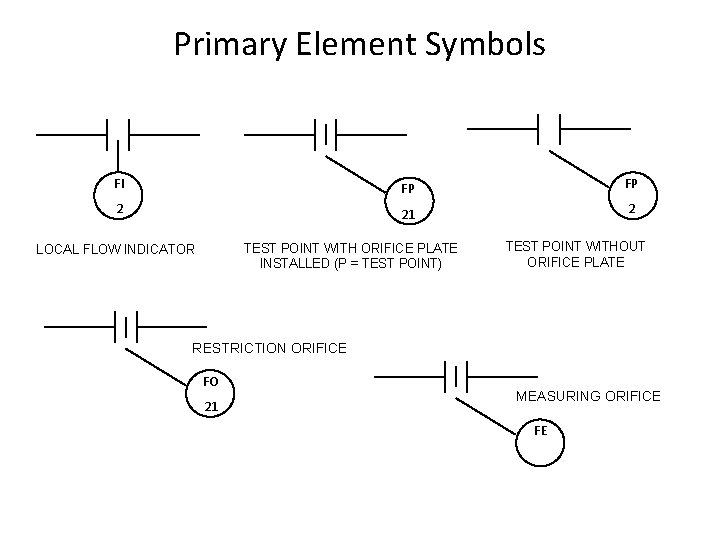
Primary Element Symbols FI FP 2 21 2 TEST POINT WITH ORIFICE PLATE INSTALLED (P = TEST POINT) LOCAL FLOW INDICATOR TEST POINT WITHOUT ORIFICE PLATE RESTRICTION ORIFICE FO 21 MEASURING ORIFICE FE
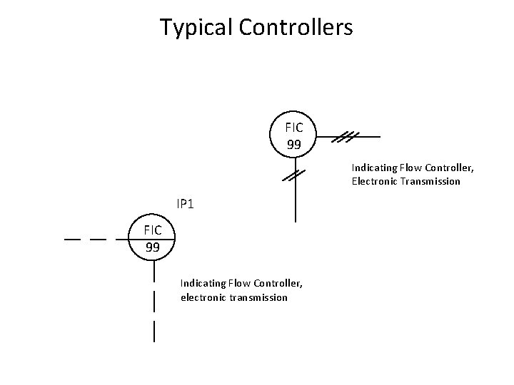
Typical Controllers FIC 99 Indicating Flow Controller, Electronic Transmission IP 1 FIC 99 Indicating Flow Controller, electronic transmission
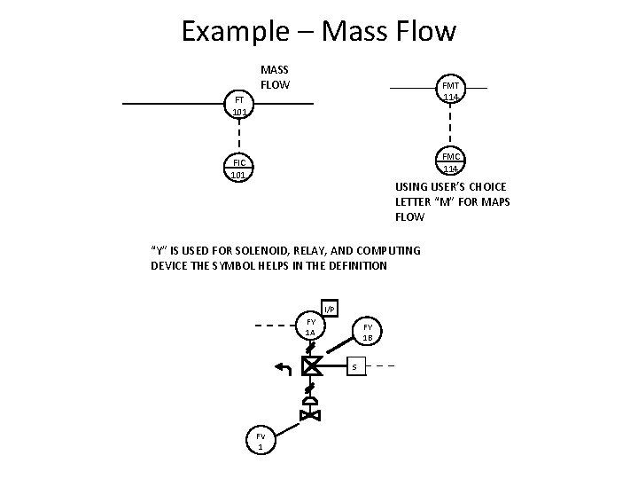
Example – Mass Flow MASS FLOW FMT 114 FT 101 FMC 114 FIC 101 USING USER’S CHOICE LETTER “M” FOR MAPS FLOW “Y” IS USED FOR SOLENOID, RELAY, AND COMPUTING DEVICE THE SYMBOL HELPS IN THE DEFINITION I/P FY 1 A FY 1 B S FV 1
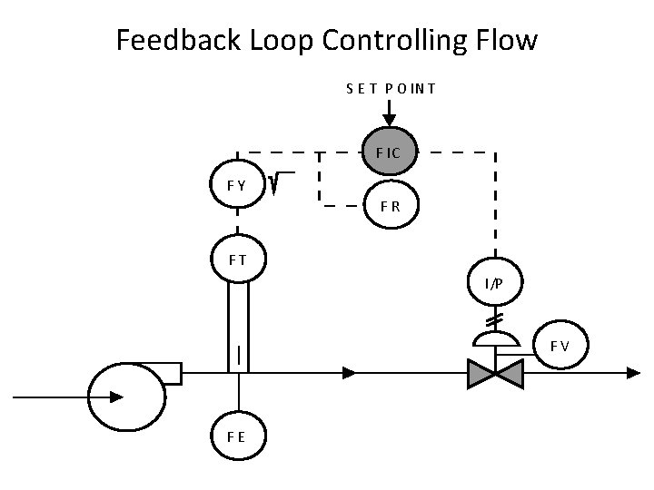
Feedback Loop Controlling Flow S E T P O IN T F IC FY FR FT I/P FV FE
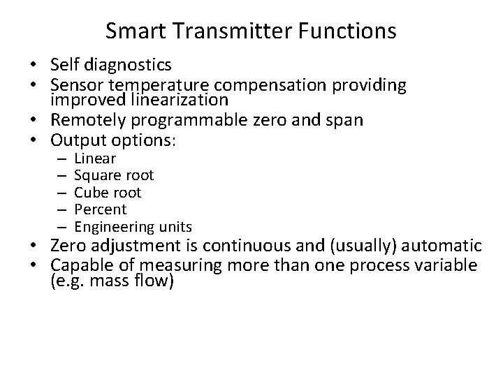
Smart Transmitter Functions • Self diagnostics • Sensor temperature compensation providing improved linearization • Remotely programmable zero and span • Output options: – – – Linear Square root Cube root Percent Engineering units • Zero adjustment is continuous and (usually) automatic • Capable of measuring more than one process variable (e. g. mass flow)
Mass Flow Example • Smart instruments are capable of measuring more than one variable (e. g. . . temp and pressure in one instrument) • Some of the recent developments use the in built microprocessor to calculate mass flow using the principle of measuring more than one variable
PRT 101 Introduction to Process Technology Chapter 6 – Process variables, Elements, & instruments: Analytical
Purpose of Analytical devices • • Environmental monitoring & reporting Mechanical integrity of Fixed Equipment Economics Product Quality assurance
Common Types of Analyzers • p. H & ORP meters • Conductivity meters • Optical Analyzer (color, turbidity, and/or opacity) • Gas Chromatograph (CG) & CG Mass Spectrometer • Spectrometer (UV/VIS and/ or Infrared • Total Carbon Analyzer
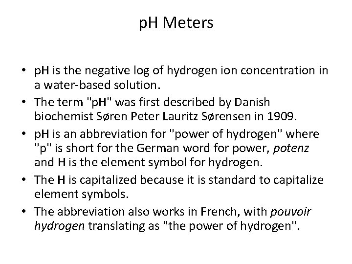
p. H Meters • p. H is the negative log of hydrogen ion concentration in a water-based solution. • The term "p. H" was first described by Danish biochemist Søren Peter Lauritz Sørensen in 1909. • p. H is an abbreviation for "power of hydrogen" where "p" is short for the German word for power, potenz and H is the element symbol for hydrogen. • The H is capitalized because it is standard to capitalize element symbols. • The abbreviation also works in French, with pouvoir hydrogen translating as "the power of hydrogen".
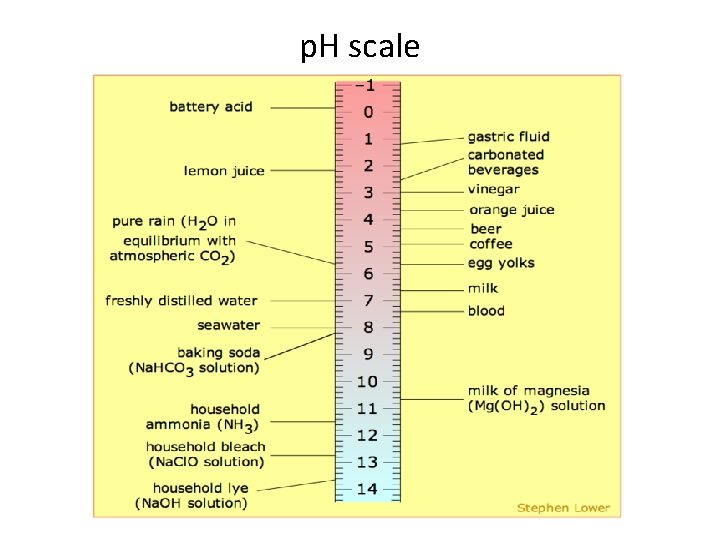
p. H scale
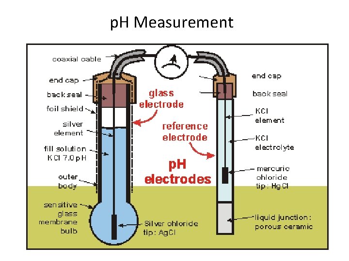
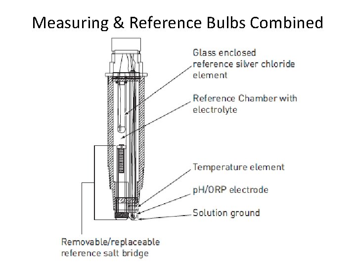
p. H Measurement
Measuring & Reference Bulbs Combined
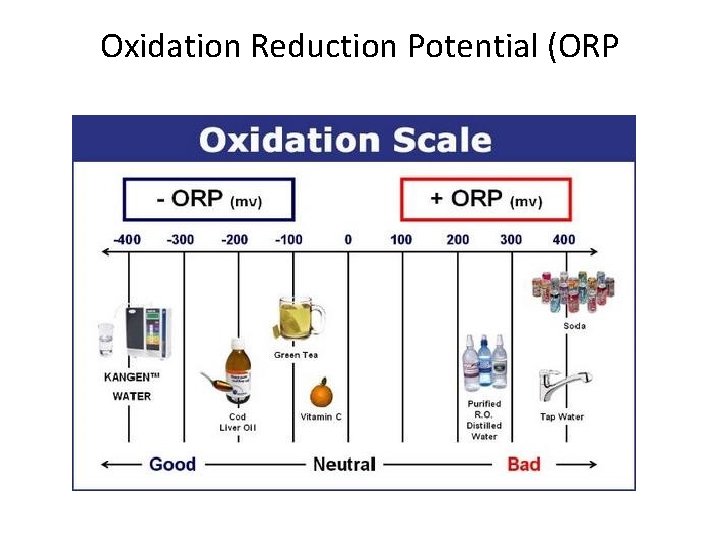
Oxidation Reduction Potential (ORP) • ORP is a measure of the cleanliness of the water & its ability to break down contaminants. • It has a range of – 2, 000 to + 2, 000 and units are in “m. V” (millivolts). • Since ozone is an oxidizer, we are only concerned with positive ORP levels (above 0 m. V).
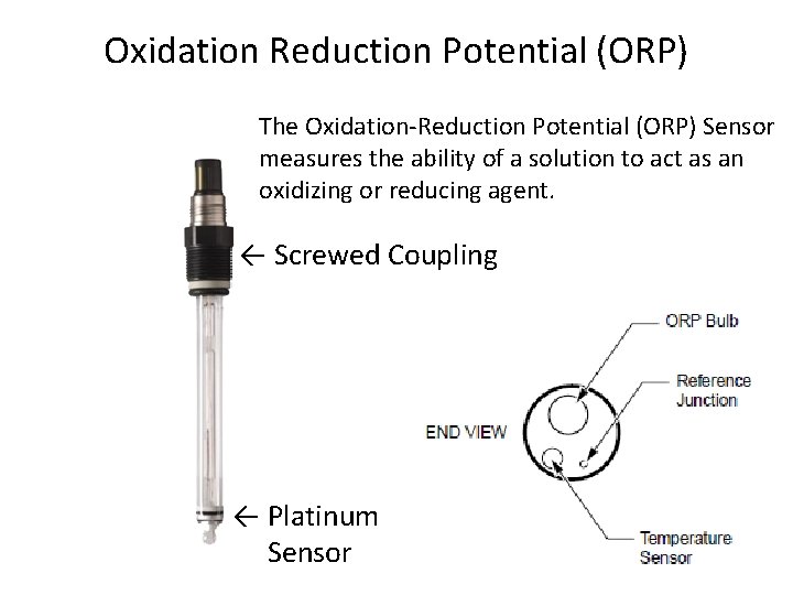
Oxidation Reduction Potential (ORP) The Oxidation-Reduction Potential (ORP) Sensor measures the ability of a solution to act as an oxidizing or reducing agent. ← Screwed Coupling ← Platinum Sensor
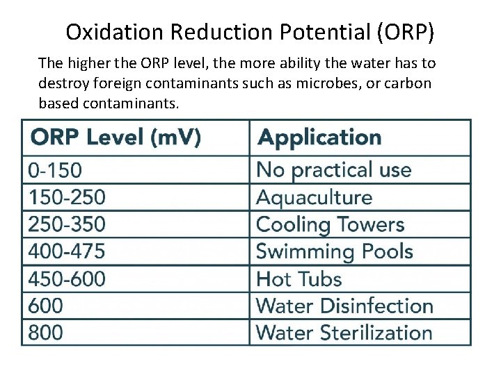
Oxidation Reduction Potential (ORP) The higher the ORP level, the more ability the water has to destroy foreign contaminants such as microbes, or carbon based contaminants.
Oxidation Reduction Potential (ORP
What is Kanga Water? • There are several benefits of Kangen alkaline water. An individual can use alkaline ionized water at home for various purposes. Among others these include household cleaning, cooking, personal care, pet care. Kangen water contains also several elements like sodium, potassium, calcium and magnesium. • It may be “poison” to some.
What is R. O. Distilled Water • “Distilled water is totally devoid of all minerals, and prolonged use of it may leach out the body’s own mineral reserves and lead to severe mineral deficiencies and such diseases as osteoporosis, diabetes, tooth decay and heart disease. ” • R. O. = Reversed Osmosis
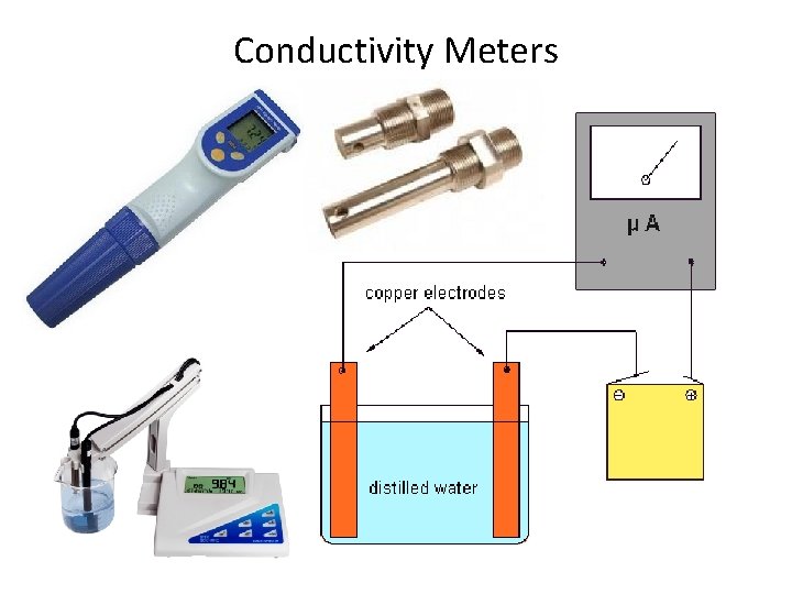
Conductivity Meters
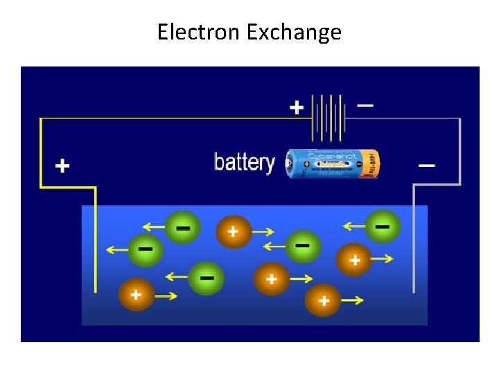
Electron Exchange
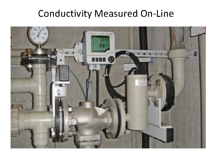
Conductivity Measured On-Line
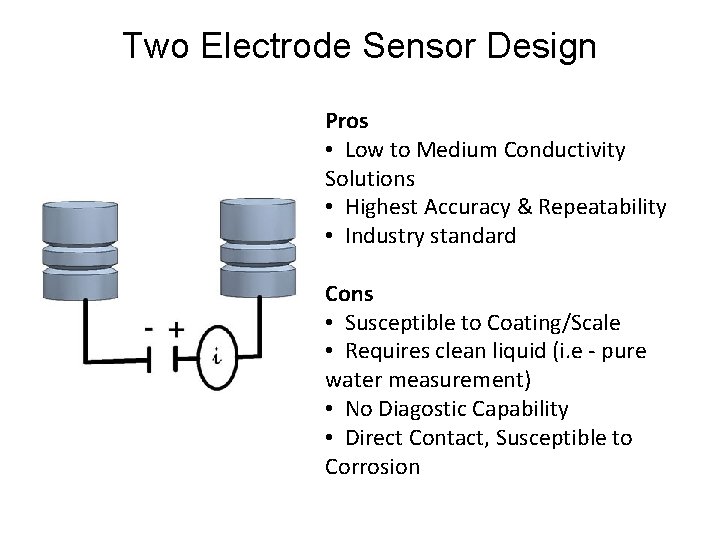
Two Electrode Sensor Design Pros • Low to Medium Conductivity Solutions • Highest Accuracy & Repeatability • Industry standard Cons • Susceptible to Coating/Scale • Requires clean liquid (i. e - pure water measurement) • No Diagostic Capability • Direct Contact, Susceptible to Corrosion
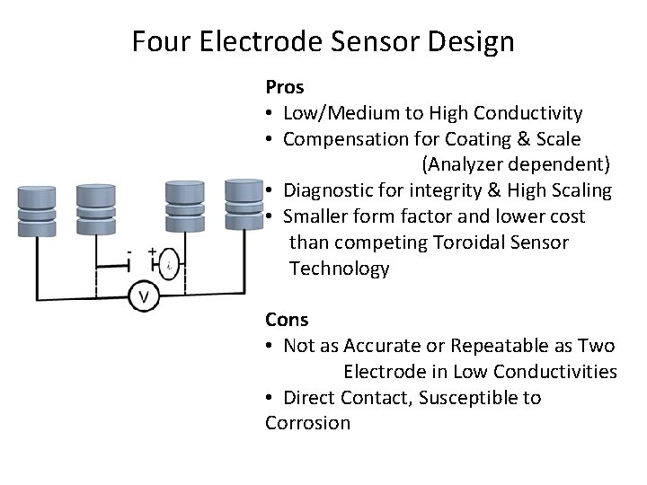
Four Electrode Sensor Design Pros • Low/Medium to High Conductivity • Compensation for Coating & Scale (Analyzer dependent) • Diagnostic for integrity & High Scaling • Smaller form factor and lower cost than competing Toroidal Sensor Technology Cons • Not as Accurate or Repeatable as Two Electrode in Low Conductivities • Direct Contact, Susceptible to Corrosion
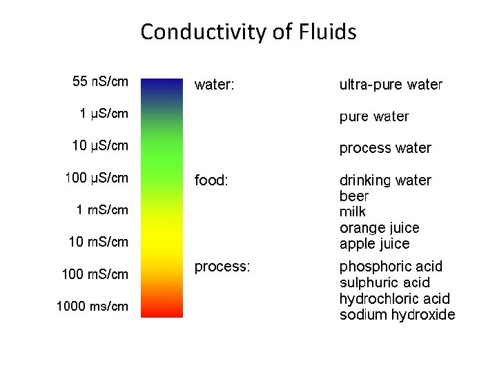
Conductivity of Fluids
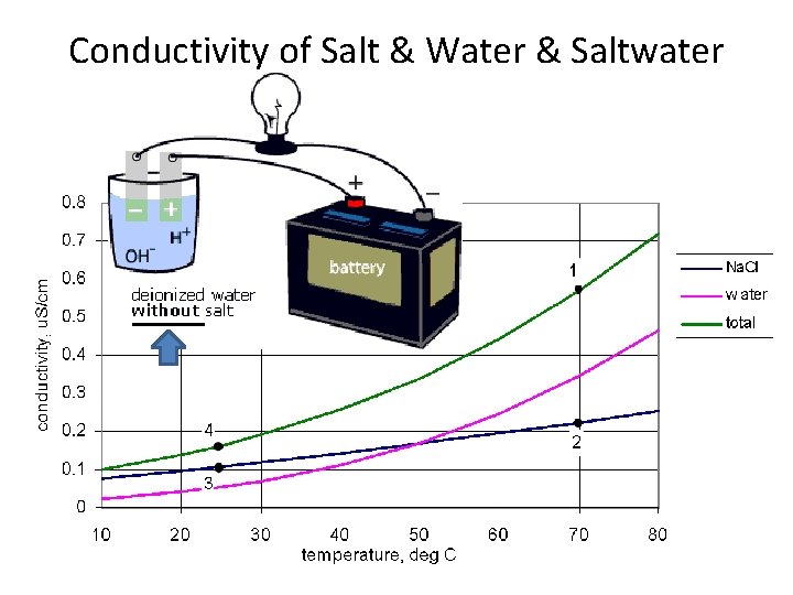
Conductivity of Salt & Water & Saltwater
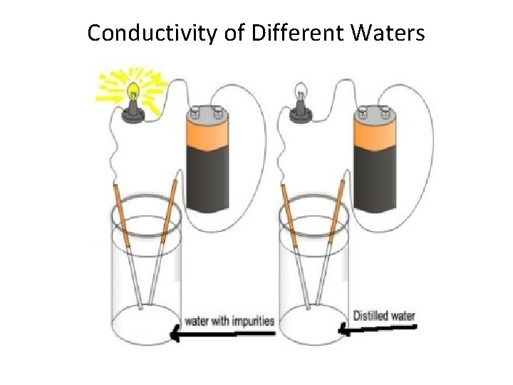
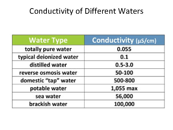
Conductivity of Different Waters
Conductivity of Different Waters
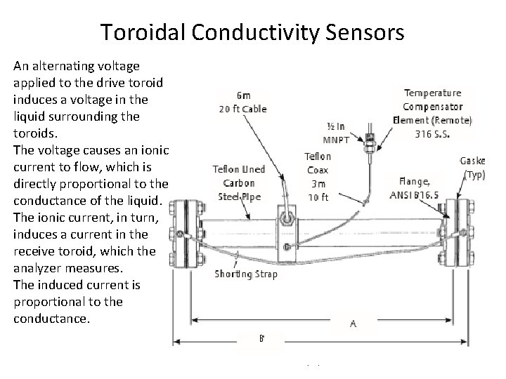
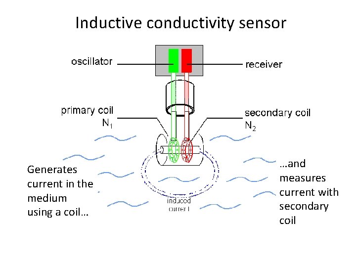
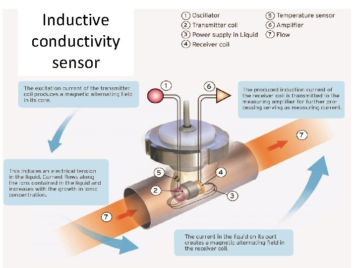
Toroidal Conductivity Sensors An alternating voltage applied to the drive toroid induces a voltage in the liquid surrounding the toroids. The voltage causes an ionic current to flow, which is directly proportional to the conductance of the liquid. The ionic current, in turn, induces a current in the receive toroid, which the analyzer measures. The induced current is proportional to the conductance.
Inductive conductivity sensor Generates current in the medium using a coil… …and measures current with secondary coil
Inductive conductivity sensor
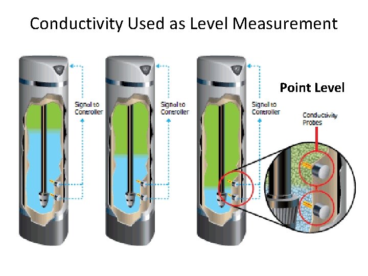
Conductivity Used as Level Measurement Point Level
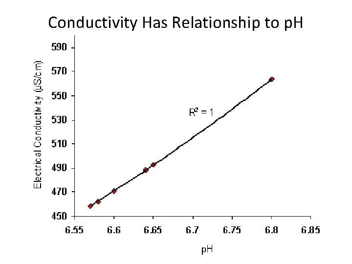
Conductivity Has Relationship to p. H
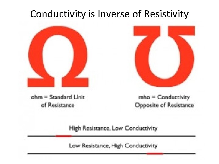
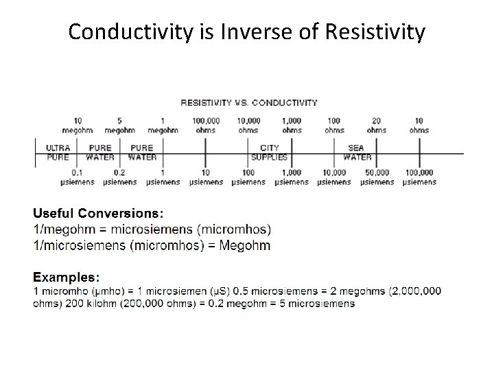
Conductivity is Inverse of Resistivity
Conductivity is Inverse of Resistivity
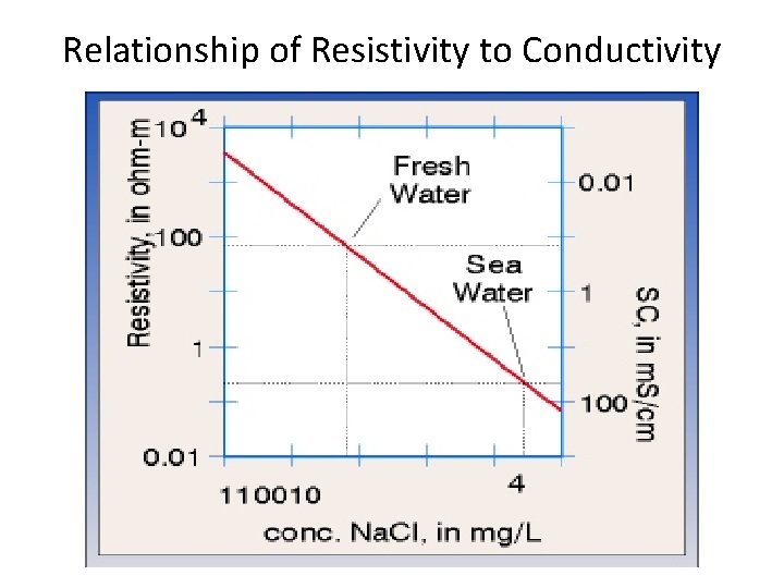
Relationship of Resistivity to Conductivity
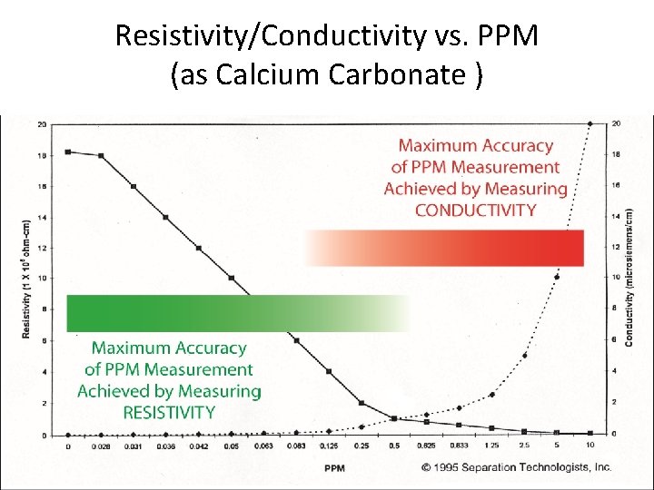
Resistivity/Conductivity vs. PPM (as Calcium Carbonate )
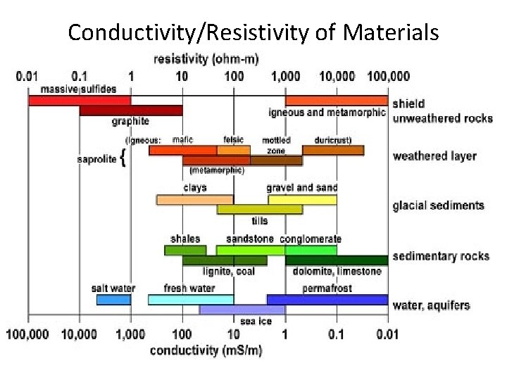
Conductivity/Resistivity of Materials
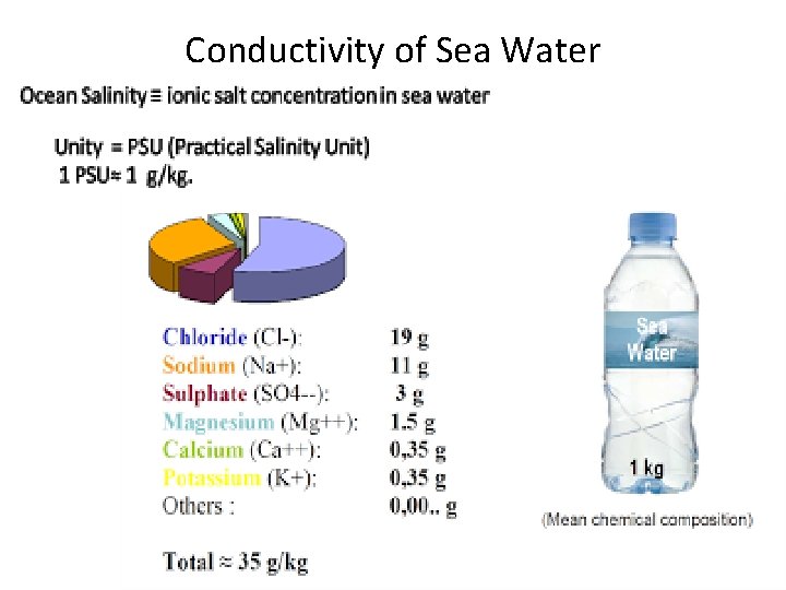
Conductivity of Sea Water
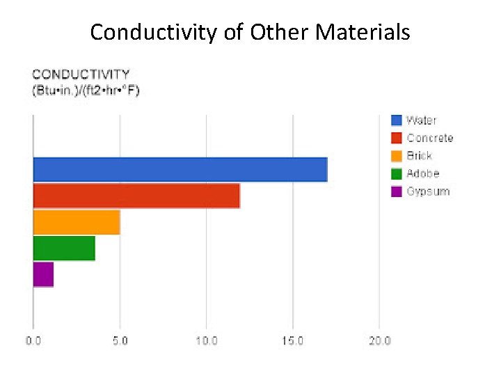
Conductivity of Other Materials
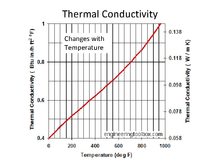
Thermal Conductivity Changes with Temperature
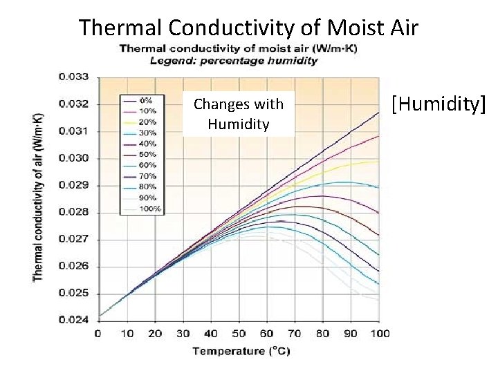
Thermal Conductivity of Moist Air Changes with Humidity [Humidity]
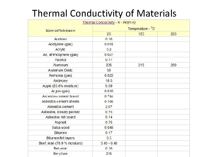
Thermal Conductivity of Materials
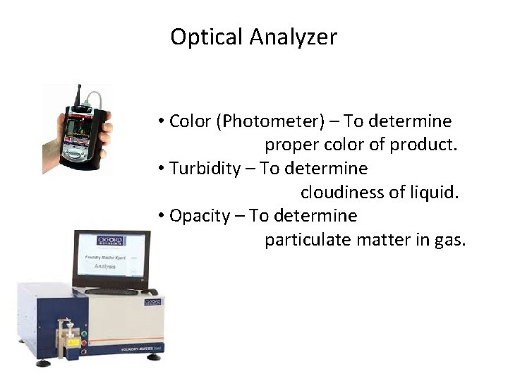
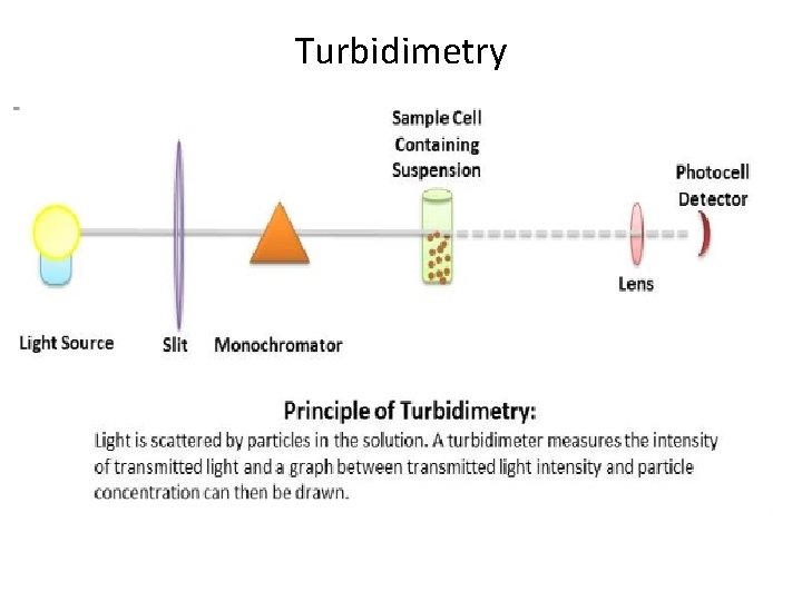
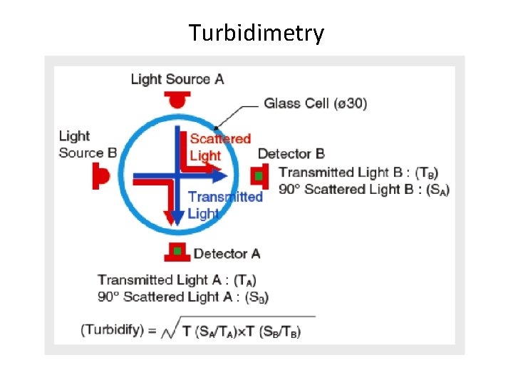
Optical Analyzer • Color (Photometer) – To determine proper color of product. • Turbidity – To determine cloudiness of liquid. • Opacity – To determine particulate matter in gas.
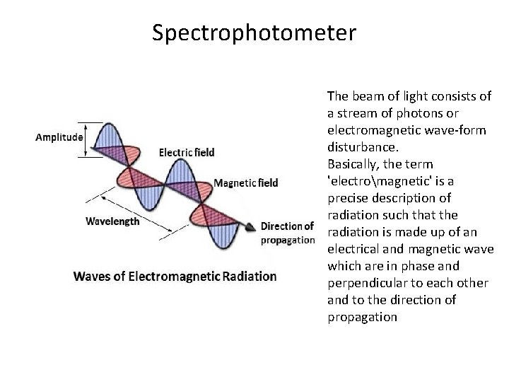
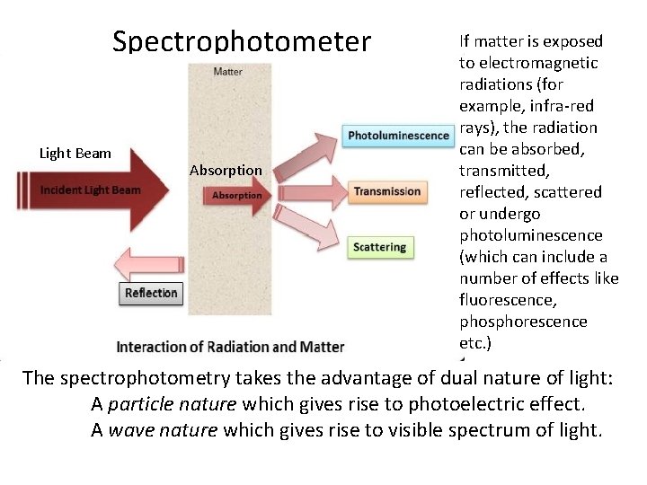
Spectrophotometer The beam of light consists of a stream of photons or electromagnetic wave-form disturbance. Basically, the term 'electromagnetic' is a precise description of radiation such that the radiation is made up of an electrical and magnetic wave which are in phase and perpendicular to each other and to the direction of propagation
Spectrophotometer Light Beam Absorption If matter is exposed to electromagnetic radiations (for example, infra-red rays), the radiation can be absorbed, transmitted, reflected, scattered or undergo photoluminescence (which can include a number of effects like fluorescence, phosphorescence etc. ) The spectrophotometry takes the advantage of dual nature of light: A particle nature which gives rise to photoelectric effect. A wave nature which gives rise to visible spectrum of light.
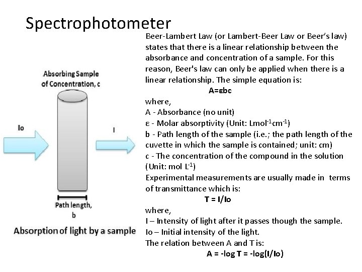
Spectrophotometer Beer-Lambert Law (or Lambert-Beer Law or Beer’s law) states that there is a linear relationship between the absorbance and concentration of a sample. For this reason, Beer's law can only be applied when there is a linear relationship. The simple equation is: A=εbc where, A - Absorbance (no unit) ε - Molar absorptivity (Unit: Lmol-1 cm-1) b - Path length of the sample (i. e. ; the path length of the cuvette in which the sample is contained; unit: cm) c - The concentration of the compound in the solution (Unit: mol L-1) Experimental measurements are usually made in terms of transmittance which is: T = I/Io where, I – Intensity of light after it passes though the sample. Io – Initial intensity of the light. The relation between A and T is: A = -log T = -log(I/Io)
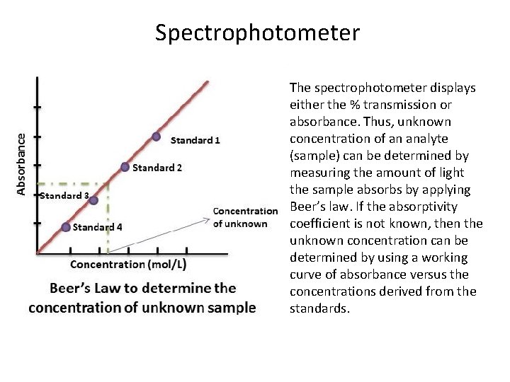
Spectrophotometer The spectrophotometer displays either the % transmission or absorbance. Thus, unknown concentration of an analyte (sample) can be determined by measuring the amount of light the sample absorbs by applying Beer’s law. If the absorptivity coefficient is not known, then the unknown concentration can be determined by using a working curve of absorbance versus the concentrations derived from the standards.
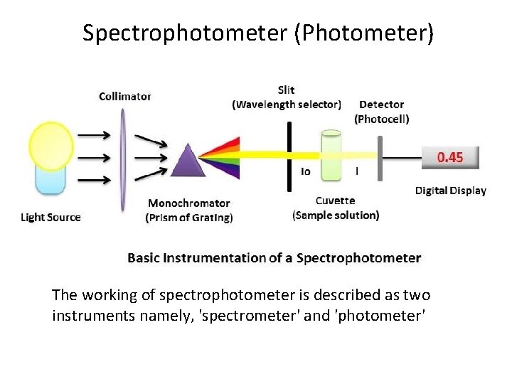
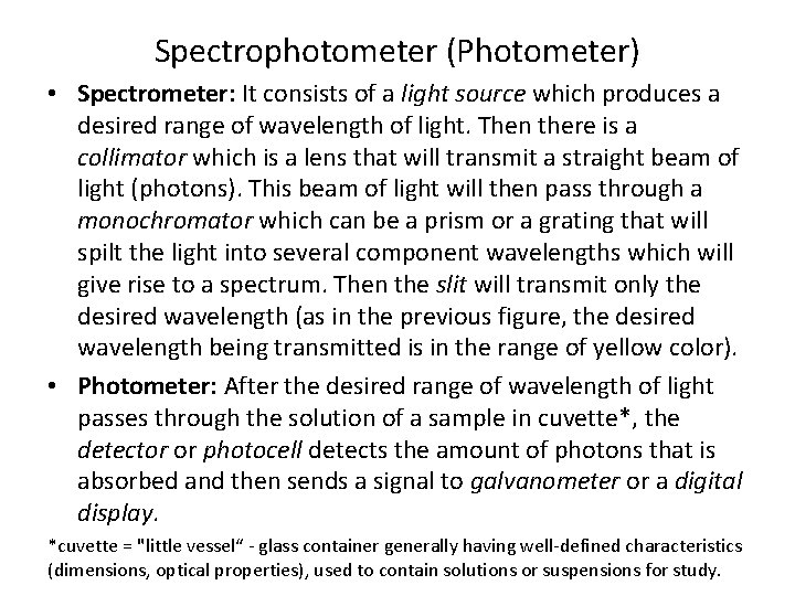
Spectrophotometer (Photometer) The working of spectrophotometer is described as two instruments namely, 'spectrometer' and 'photometer'
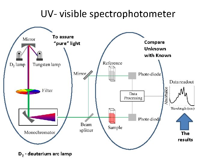
Spectrophotometer (Photometer) • Spectrometer: It consists of a light source which produces a desired range of wavelength of light. Then there is a collimator which is a lens that will transmit a straight beam of light (photons). This beam of light will then pass through a monochromator which can be a prism or a grating that will spilt the light into several component wavelengths which will give rise to a spectrum. Then the slit will transmit only the desired wavelength (as in the previous figure, the desired wavelength being transmitted is in the range of yellow color). • Photometer: After the desired range of wavelength of light passes through the solution of a sample in cuvette*, the detector or photocell detects the amount of photons that is absorbed and then sends a signal to galvanometer or a digital display. *cuvette = "little vessel“ - glass container generally having well-defined characteristics (dimensions, optical properties), used to contain solutions or suspensions for study.
UV- visible spectrophotometer To assure “pure” light Compare Unknown with Known The results D 2 - deuterium arc lamp
Turbidimetry
Turbidimetry
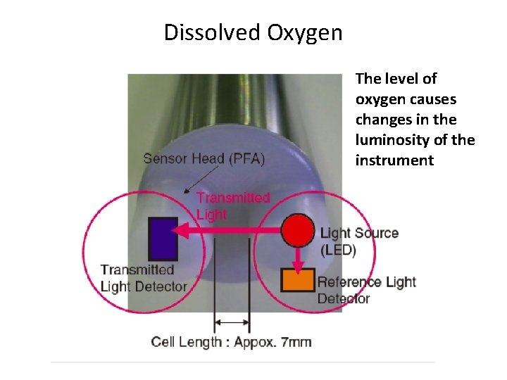
Dissolved Oxygen The level of oxygen causes changes in the luminosity of the instrument
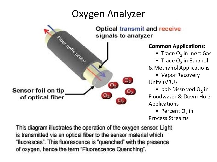
Oxygen Analyzer Common Applications: • Trace O 2 in Inert Gas • Trace O 2 in Ethanol & Methanol Applications • Vapor Recovery Units (VRU) • ppb Dissolved O 2 in Floodwater & Down Hole Applications • Percent O 2 in Process Streams
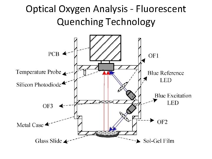
Optical Oxygen Analysis - Fluorescent Quenching Technology
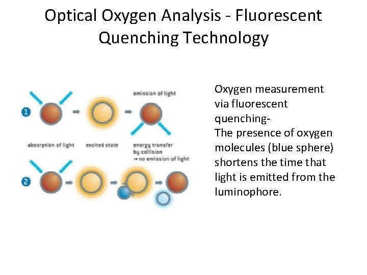
Optical Oxygen Analysis - Fluorescent Quenching Technology Oxygen measurement via fluorescent quenching- The presence of oxygen molecules (blue sphere) shortens the time that light is emitted from the luminophore.
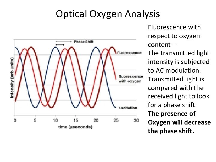
Optical Oxygen Analysis Fluorescence with respect to oxygen content – The transmitted light intensity is subjected to AC modulation. Transmitted light is compared with the received light to look for a phase shift. The presence of Oxygen will decrease the phase shift.
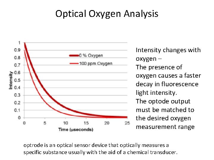
Optical Oxygen Analysis Intensity changes with oxygen – The presence of oxygen causes a faster decay in fluorescence light intensity. The optode output must be matched to the desired oxygen measurement range optrode is an optical sensor device that optically measures a specific substance usually with the aid of a chemical transducer.
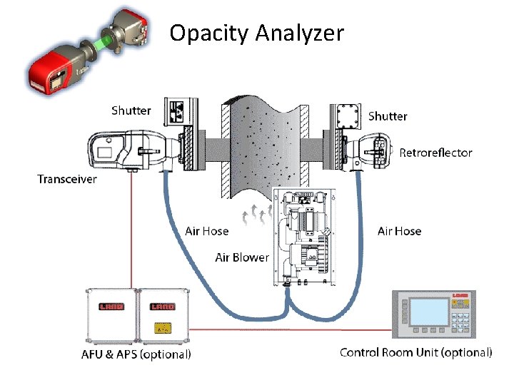
Opacity Analyzer
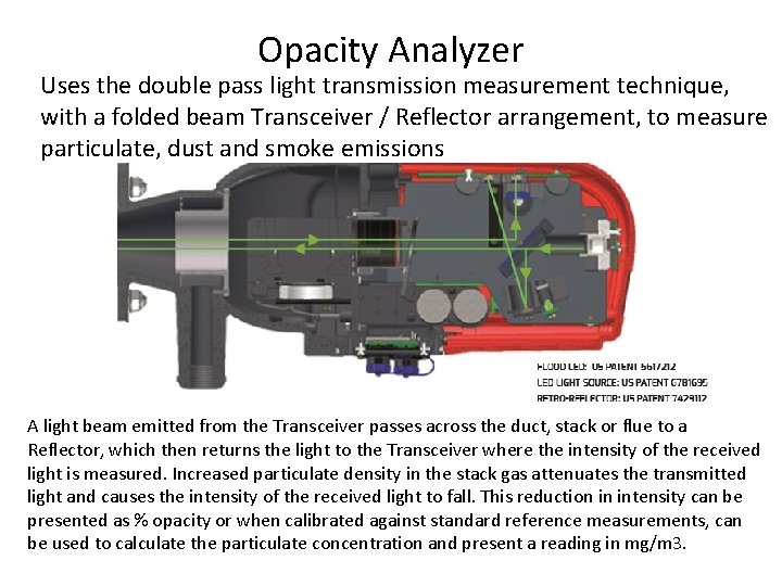
Opacity Analyzer Uses the double pass light transmission measurement technique, with a folded beam Transceiver / Reflector arrangement, to measure particulate, dust and smoke emissions A light beam emitted from the Transceiver passes across the duct, stack or flue to a Reflector, which then returns the light to the Transceiver where the intensity of the received light is measured. Increased particulate density in the stack gas attenuates the transmitted light and causes the intensity of the received light to fall. This reduction in intensity can be presented as % opacity or when calibrated against standard reference measurements, can be used to calculate the particulate concentration and present a reading in mg/m 3.
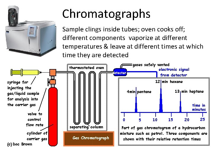
Chromatographs Sample clings inside tubes; oven cooks off; different components vaporize at different temperatures & leave at different times at which time they are detected
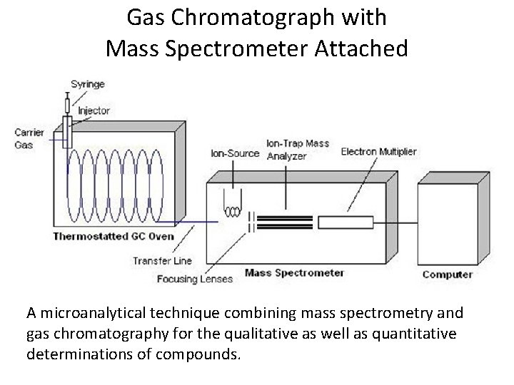
Gas Chromatograph with Mass Spectrometer Attached A microanalytical technique combining mass spectrometry and gas chromatography for the qualitative as well as quantitative determinations of compounds.
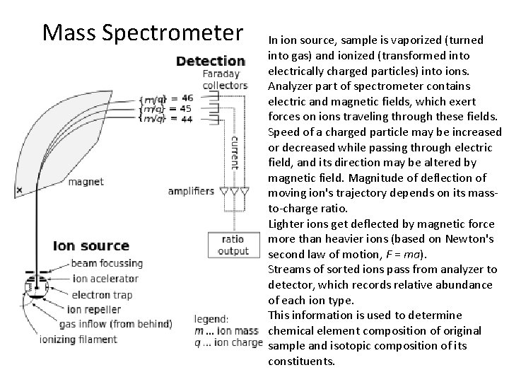
Mass Spectrometer In ion source, sample is vaporized (turned into gas) and ionized (transformed into electrically charged particles) into ions. Analyzer part of spectrometer contains electric and magnetic fields, which exert forces on ions traveling through these fields. Speed of a charged particle may be increased or decreased while passing through electric field, and its direction may be altered by magnetic field. Magnitude of deflection of moving ion's trajectory depends on its massto-charge ratio. Lighter ions get deflected by magnetic force more than heavier ions (based on Newton's second law of motion, F = ma). Streams of sorted ions pass from analyzer to detector, which records relative abundance of each ion type. This information is used to determine chemical element composition of original sample and isotopic composition of its constituents.
Total Organic Carbon (TOC) Analyzers Online Total Organic Carbon (TOC) analyzers can be used at wastewater treatment plants to monitor final effluent for regulatory reporting purposes and at various points throughout treatment process for preventative control. Online TOC monitoring at the primary effluent stage provides a feed-forward control strategy for managing plant waste loads and preventing plant upsets. Manufacturers use different methodologies for such functions as sample transport, sample conditioning, chemical addition, primary measurement, and secondary signal conditioning and amplification. Automatic calibration and cleaning cycles are options.
Total Organic Carbon (TOC) Analyzers Currently, there are several major types of instrument technologies used for online TOC analyzers: · High Temperature Catalytic/Combustion Oxidation (HTCO) · Supercritical Water Oxidation (SCWO) · Patented Two-Stage Advanced Oxidation (TSAO) Process using Hydroxyl Radicals · Heated Persulfate Ultraviolet (UV) Oxidation Total Carbon (TC) of a wastewater sample is typically composed of a mixture of total organic carbon (TOC) and inorganic carbon (IC) or mathematically TC = TOC + IC or TOC = TC — IC. Using these equations, there are two methods to determine TOC. One method is to measure TC and IC independently and subtracting the IC from the TC. The second method uses an acid to carbonate the sample to chemically remove the IC from the sample and leaving only the TOC in the sample for analysis by the instrument. All online TOC analyzer technologies oxidize the total organic carbon samples to break the sample’s organic carbon down into a carbon dioxide (CO 2) gas. The CO 2 gas is measured by a Nondispersive Infrared (NDIR) detector.
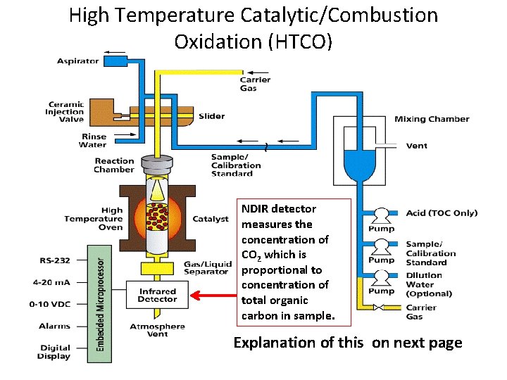
High Temperature Catalytic/Combustion Oxidation (HTCO) NDIR detector measures the concentration of CO 2 which is proportional to concentration of total organic carbon in sample. Explanation of this on next page
High Temperature Catalytic/Combustion Oxidation (HTCO) online TOC analyzer technology first acidifies sample to a p. H of less than 2 which converts carbonates (inorganic carbon) in sample to carbonic acid (dissolved carbon dioxide or CO 2). Sample is then purged (sparged) with carrier gas to remove the CO 2. Organic carbon remaining in sample is oxidized to CO 2 using catalyst and high temperature oven maintained at 900 degrees Celsius. Continuously flowing carrier gas transfers the CO 2 into nondispersive infrared (NDIR) detector. NDIR detector measures the concentration of CO 2 which is proportional to concentration of total organic carbon in sample. Previous figure displays generic online HTCO TOC analyzer.
Summery of Common Types of Analyzers • p. H & ORP meters • Conductivity meters • Optical Analyzer (color, turbidity, and/or opacity) • Gas Chromatograph (CG) & CG Mass Spectrometer • Spectrometer (UV/VIS and/ or Infrared • Total Carbon Analyzer
Next week: Test # 1 Chapters 1 - 6 ONLY!