
PROVISIONS OF MANUAL FOR ULTRASONIC TESTING OF RAILS


- Slides: 177
PROVISIONS OF MANUAL FOR ULTRASONIC TESTING OF RAILS AND WELDS By R. K. Kathal Associate Prof. Track
CONTENT CHAPTERS: -13 ANNEXURES: - 8 FIGUERS : - 56
RAIL DEFECTS AND THEIR CODIFICATION Rail is the most important and critical component of the permanent way. Most common cause of rail failure is the fatigue fracture, which is due to imperfections present in the material or due to crack formation during service. Thus successful performance of rails is based on their resistance to crack initiation and crack propagation. It is therefore essential to identify and classify the defects in rails and in turn initiate corrective action.
Causes of defects Material defects originating during the manufacturing process such as clusters of non-metallic inclusions, hydrogen flakes, rolling marks, guide marks etc. Which may be present in spite of successful non-destructive tests carried out on the rails during quality assurance examination.
Causes of defects Residual stresses induced during manufacture (cooling, rolling, gas pressing and straightening). Defects due to incorrect handling e. g. plastic deformation, scoring, denting, etc. Defects associated with faulty welding i. e. gas pores, lack of fusion, inclusions, cracks etc.
Causes of defects Dynamic stresses caused by vertical and lateral loads particularly by vehicles with wheel flats or when the vehicle runs over poorly maintained rail joints etc. Excessive thermal stresses due to variation in rail temperature beyond specified limits.
Defect location In order to study the fractures in rail systematically, they may be divided into the following categories based on their location of occurrence in the rail length: (a)Defects emanating from the rail end or reaching the end of the rail. (b) Defects observed within fish-plated zone. (c) Defects not covered in (a) and (b).
Nature of defects in rails Horizontal crack in head: These cracks run usually parallel to the rail table at a depth of 10 -20 mm and may finally split the material layer. Crushing of the railhead may also be observed in the vicinity of the crack. Clusters of non-metallic inclusions and abnormal vertical service stresses are the factors responsible for this defect. USFD can easily detect such flaws.
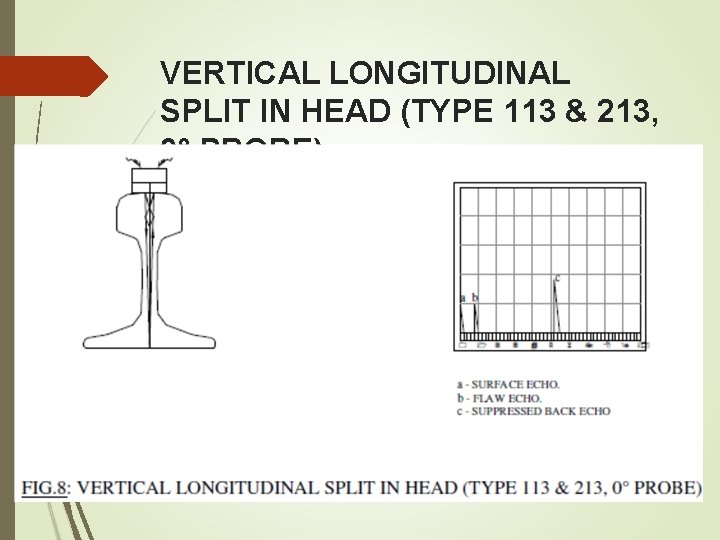
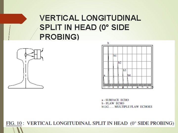
Vertical-longitudinal split in head These cracks run parallel to the longitudinal axis of the rail and are caused by presence of non-metallic inclusions, poor maintenance of joints and high dynamic stresses. It cannot be easily detected in early stages by USFD due to their unfavourable orientation.
Horizontal crack at head web junction Such flaws may lead to rail head separation. Contributory causes are wheel flats, bad fishplated joint, inclusions and high residual stresses. USFD is sensitive to such defects and can easily detect them.
Horizontal crack at web-foot junction Such cracks develop both towards head and foot. They are caused by high vertical and lateral dynamic loads, scoring and high residual stresses. USFD can easily detect these flaws.
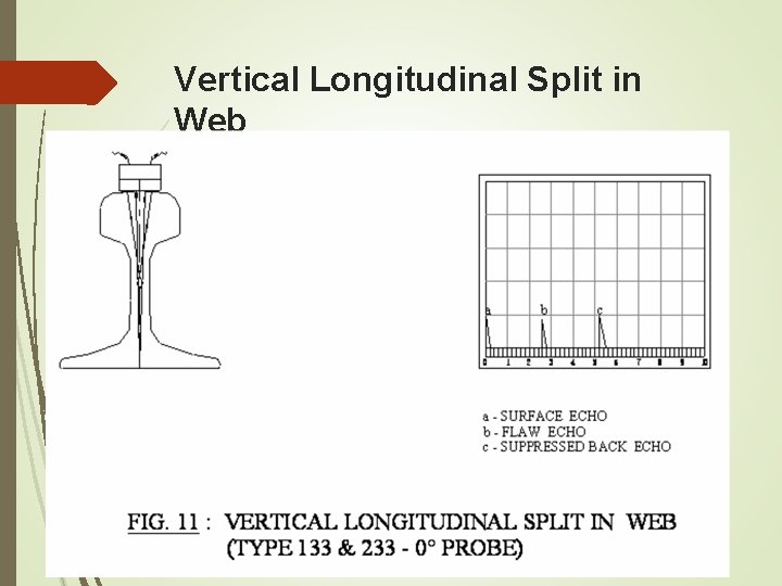
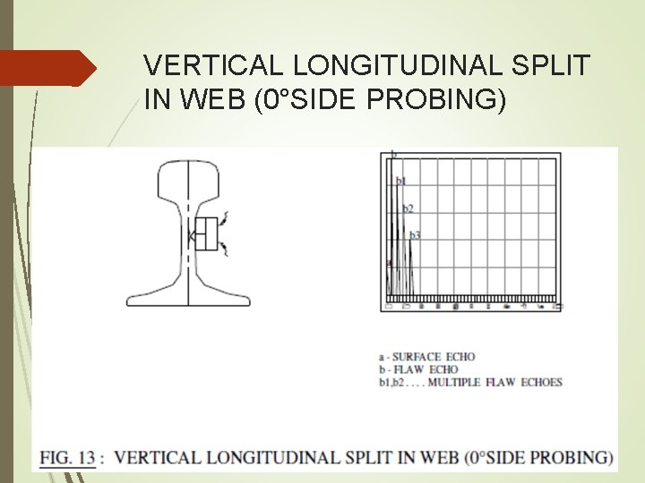
Vertical longitudinal splitting of the web It is primarily due to heavy accumulation of non-metallic inclusions and wheel flats. USFD conducted from rail top can detect it only if the defect is severe and in an advanced stage. Vertical longitudinal defects of minor nature are not amenable to USFD examination conducted from rail top. Probing from railhead sides can detect such defects for which hand probing may be essential.
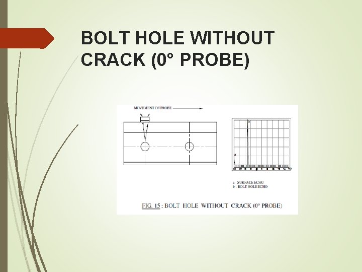
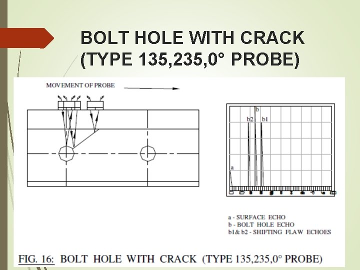
Bolt hole crack Such cracks often run diagonally and may run towards head or the foot. They result from inadequately maintained joints and un chamfered fish boltholes and stress concentration. USFD can easily detect these cracks. Normal probes provide indication as diminished back wall echo.
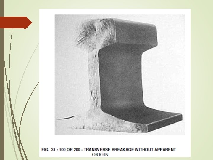
Transverse fracture without apparent origin These fractures occur suddenly, especially during winter and may emanate from microscopic flaws (embedded or on surface) and are generally very difficult to detect by USFD. These minute flaws manifest suddenly under severe service conditions or when the fracture toughness values are comparatively low.
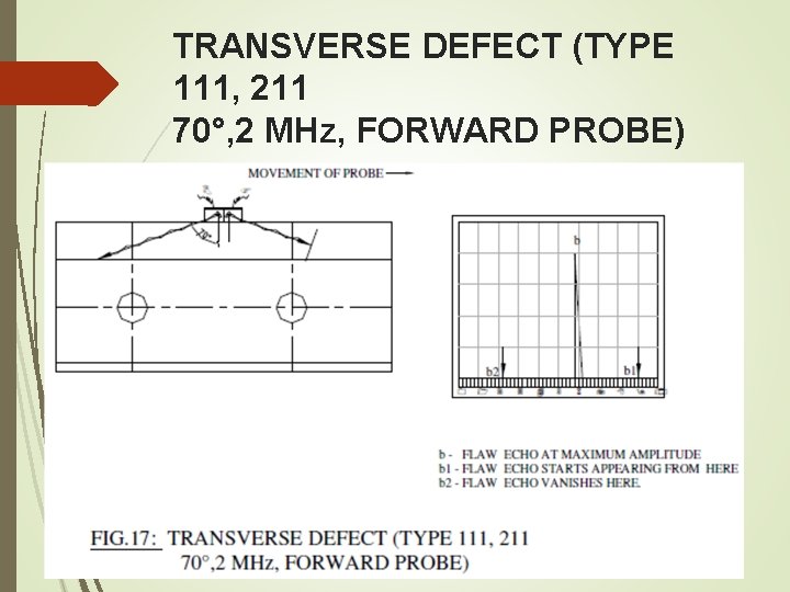
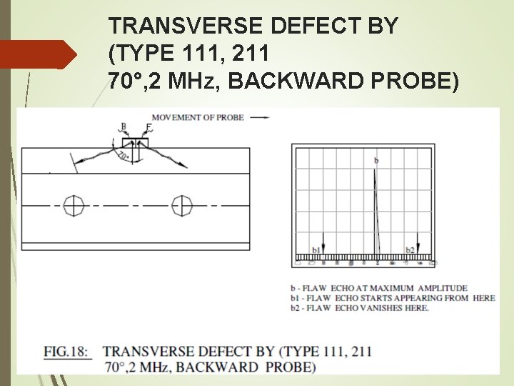
Transverse fatigue crack in head They resemble a kidney in shape in the railhead and USFD is ideally suited for detecting them. They are generally inclined at the angle of 18 ﹾ -23 ﹾ and originate at a depth of 15 -20 mm below the running surface. Mainly hydrogen accumulation and non-metallic inclusions cause this defect. These cracks are easily detected by 70 ﹾ probe. When such defects are nearly vertical, they can be detected using additional gain of 10 db. Defects lying below scabs/wheel burns can be detected by 45 ﹾ side probing of rail head.
Horizontal crack at top and bottom fillet radius These cracks are caused by accumulation of non-metallic inclusions and high residual stresses introduced at the time of rail straightening. These are difficult to be detected by USFD.
Vertical – longitudinal crack in foot Such cracks develop from sharp chamfers on the bottom surface of the rail foot. Cracks occurring in this way are the points of origin of transverse cracks in the foot.
Transverse cracks in rail foot Due to localised overheating during FB welding, structural changes in the bottom surface of the rail material takes place which result in a minor crack. These cracks under the tensile loading give rise to brittle fracture. Such defects are not detectable by USFD. Transverse cracks originated from AT welds in the rail foot grow as half moon and are detectable by 45 ﹾ probe.
Nature of defects in welds Joining rails by improper welding may introduce a variety of defects on the joints as well as in the heat affected zone (HAZ) e. g. lack of fusion, cracks, porosity, slag inclusion, structural variation, etc. The quality of weld depends to a large extent on the careful execution of the welding operation. USFD testing done by manual rail tester suffers from following deficiencies.
Nature of defects in welds (i) Full cross section of weld is not covered by normal USFD examination using manual tester thereby leaving areas in head and foot, which may have flaws. (ii) Micro structural variations in the weldment cause attenuation of ultrasonic energy. Therefore, a separate testing procedure for welds has been developed which is elaboratedin Chapters 8 and 9.
Defects in Flash Butt Welds (a) Transverse cracks: The origin of these cracks is the imperfection in the weldment such as lack of fusion, inclusions, etc. Fracture usually occurs from these imperfections, which may be in railhead, web or foot. During the course of its propagation USFD testing is extremely effective. (b) Horizontal cracks: These cracks develop in the web and propagate both in head and foot. The principal cause is large tensile residual stresses acting in the vertical direction.
Defects in Alumino-Thermic (AT) Welds (a) Transverse crack in head and foot: It is caused by inclusions entrapped during welding, which leads to crack initiation on the foot and its growth in the web region causing fracture. Such cracks can be detected by USFD. (b) Horizontal cracks in web: These cracks occur in AT welds in which the ends having bolt holes have not been removed. The presence of holes result in unfavorable stress distribution caused due to non-uniform cooling. USFD can easily detect such flaws.
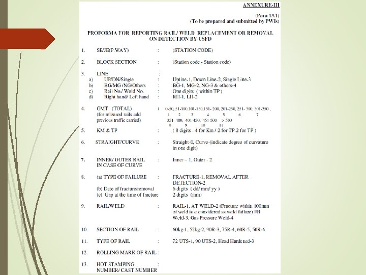
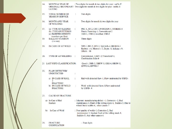
Codification of rail and weld defects Information regarding the type and nature of rail failures and their service conditions is primarily obtained through personnel responsible for maintenance of permanent way and it is of utmost importance that they are familiar with the various types and nature of rail defects and their possible causes to enable them to report the rail failures accurately. With this objective in view, it is necessary to devise a suitable coding system for reporting rail failures.
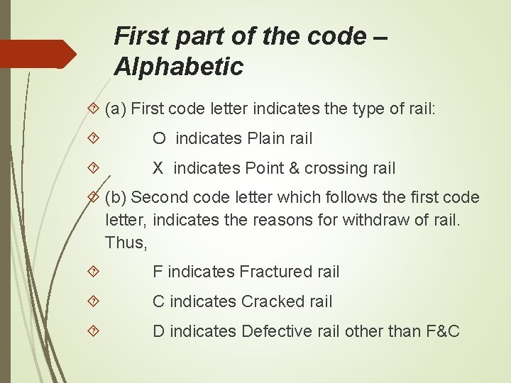
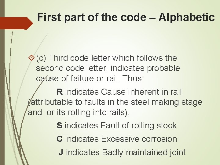
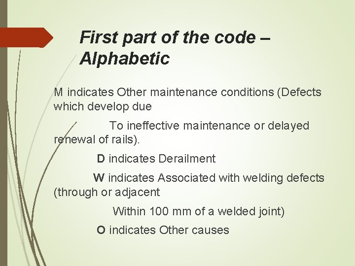
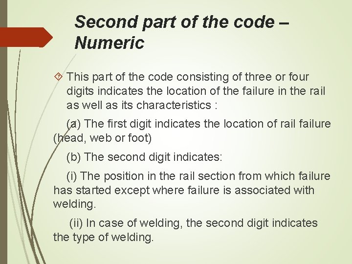
UIC has adopted an Alphanumeric system of codification of rail failures In view of its international status and the facility afforded for computerized statistical data analysis, this system has been adopted by Indian Railways for reporting rail failures. The code for reporting rail failures consists of two parts viz first – Alphabetic, consisting of three code letters and second numeric, consisting of three or four digits.
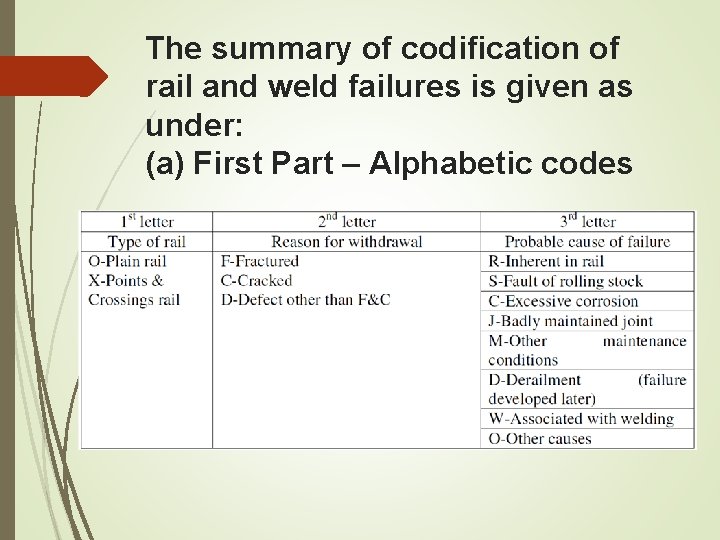
First part of the code – Alphabetic (a) First code letter indicates the type of rail: O indicates Plain rail X indicates Point & crossing rail (b) Second code letter which follows the first code letter, indicates the reasons for withdraw of rail. Thus, F indicates Fractured rail C indicates Cracked rail D indicates Defective rail other than F&C
First part of the code – Alphabetic (c) Third code letter which follows the second code letter, indicates probable cause of failure or rail. Thus: R indicates Cause inherent in rail (attributable to faults in the steel making stage and or its rolling into rails). S indicates Fault of rolling stock C indicates Excessive corrosion J indicates Badly maintained joint
First part of the code – Alphabetic M indicates Other maintenance conditions (Defects which develop due To ineffective maintenance or delayed renewal of rails). D indicates Derailment W indicates Associated with welding defects (through or adjacent Within 100 mm of a welded joint) O indicates Other causes
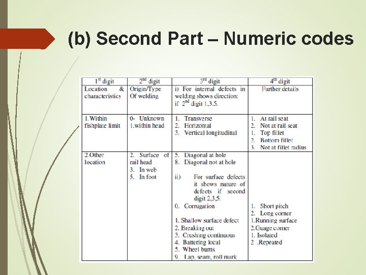
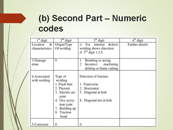
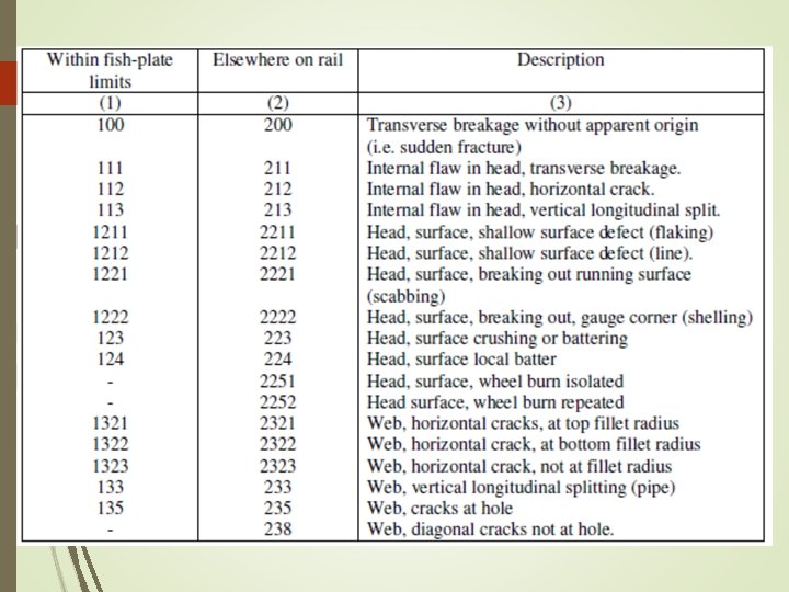
Second part of the code – Numeric This part of the code consisting of three or four digits indicates the location of the failure in the rail as well as its characteristics : (a) The first digit indicates the location of rail failure (head, web or foot) (b) The second digit indicates: (i) The position in the rail section from which failure has started except where failure is associated with welding. (ii) In case of welding, the second digit indicates the type of welding.
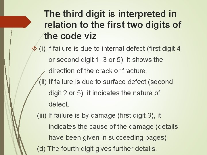
The third digit is interpreted in relation to the first two digits of the code viz (i) If failure is due to internal defect (first digit 4 or second digit 1, 3 or 5), it shows the direction of the crack or fracture. (ii) If failure is due to surface defect (second digit 2 or 5), it indicates the nature of defect. (iii) If failure is by damage (first digit 3), it indicates the cause of the damage (details have been given in succeeding pages) (d) The fourth digit gives further details.
The summary of codification of rail and weld failures is given as under: (a) First Part – Alphabetic codes
(b) Second Part – Numeric codes
(b) Second Part – Numeric codes
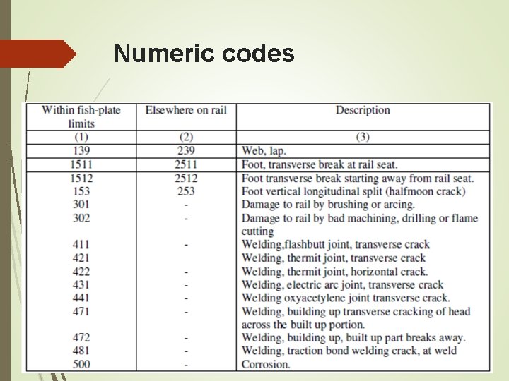
Numeric codes On the basis of the system of classification described in para 1. 3. 1. 2, a list of the failure code group to be followed is given as under, along with the meaning of the codes.
Numeric codes
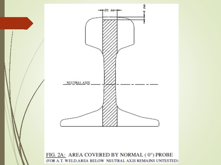
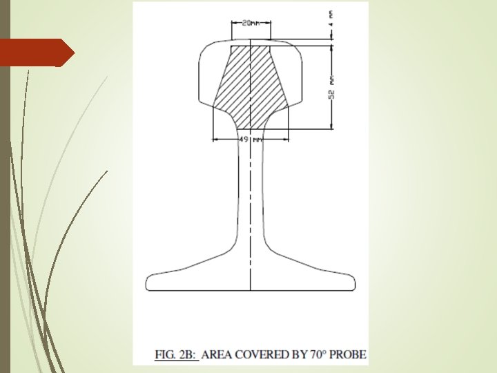
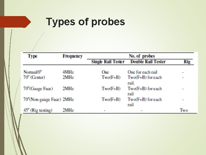
Single rail tester is capable of testing only one of the rails at a time and is provided with seven probes i. e. 0 ﹾ , 70 ﹾ Center Forward (C F), 70 ﹾ Center Backward (C B), 70 ﹾ Gauge Face Forward (GF), 70 ﹾ Gauge Face Backward (GB), 70 ﹾ Nongauge face Forward (NGF) and 70 ﹾ Non-gauge Face Backward (NGB). The normal probe (0 ) ﹾ is utilised for the purpose of detecting horizontal defects situated in head, web or foot. The 70 ﹾ probe has been specifically provided for detecting defects in the rail head, the most typical of which is the transverse fissure or kidney fracture.
Double Rail tester The double rail tester is capable of testing both the rails at a time. For each rail, seven probes have been provided for the present i. e. 0 ﹾ , 70 ﹾ Center Forward (C F), 70 ﹾ Center Backward (C B), 70 ﹾ Gauge Face Forward (G F), 70 ﹾ Gauge Face Backward (G B), 70 ﹾ Non-gauge face Forward (NGF) and 70 ﹾ Non-gauge Face Backward (NGB). The signal received from the defects by any of the probes is indicated on the screen. In order to find out the origin of detection i. e. which probe has picked up the defect, provision for displaying the individual probe operation along with audio alarm/LED display has been made in the equipment.
Double Rail tester The introduction of double rail tester has been specifically made for enhancing the productivity of testing and as well as improving the quality and accuracy of flaw detection. Due to pre-calibrated arrangement, frequent setting of the equipment is not considered necessary.
Double Rail tester Due to frequent misalignment of probes on the fishplated joints and limitations of detection of bolt hole cracks having unfavourable orientation and size, it is desirable to deploy double rail testers on LWR/CWR sections. It is desirable to deploy only the ‘single rail tester’ ultrasonic testing machine for testing of sections other than LWR/CWR.
Specification of rail testers The single and double rail testers shall be procured to RDSO specification. The responsibility of inspection for these equipment rests with Director General, RDSO. Total Life of USFD machine is approximately 8 years.
Types of probes For rails at a time and is provided with seven probes i. e. 0 ﹾ , 70 ﹾ Center Forward (C F), 70 ﹾ Center Backward (C B), 70 ﹾ Gauge Face Forward (GF), 70 ﹾ Gauge Face Backward (GB), 70 ﹾ Non-gauge face Forward (NGF) and 70 ﹾ Non-gauge Face Backward (NGB).
Types of probes
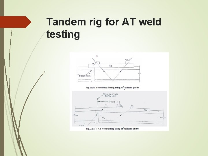
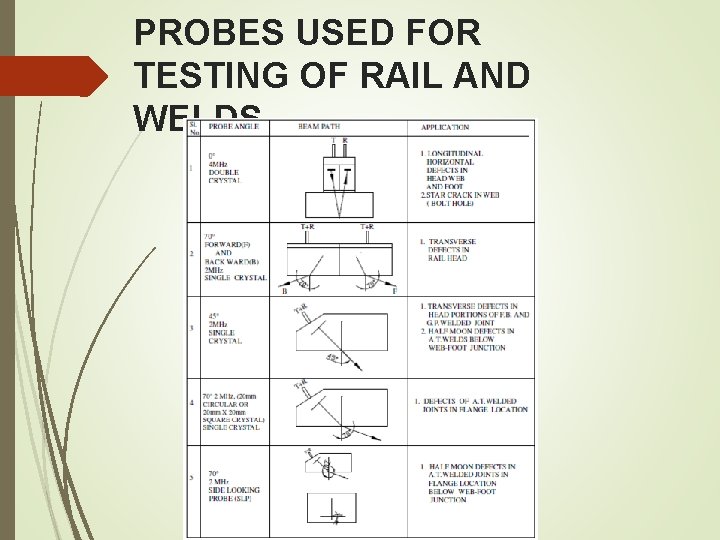
Types of probes 45 ﹾ , 2 MHz probe For testing Gas Pressure, Flashbutt Welded rail joints and half Moon Defect in AT Welds below web foot junction and SEJ. Tandem Scanning ( 2 Nos. of 45 ﹾ probes in a rig) for detection of lack of fusion in AT welded rail joints.
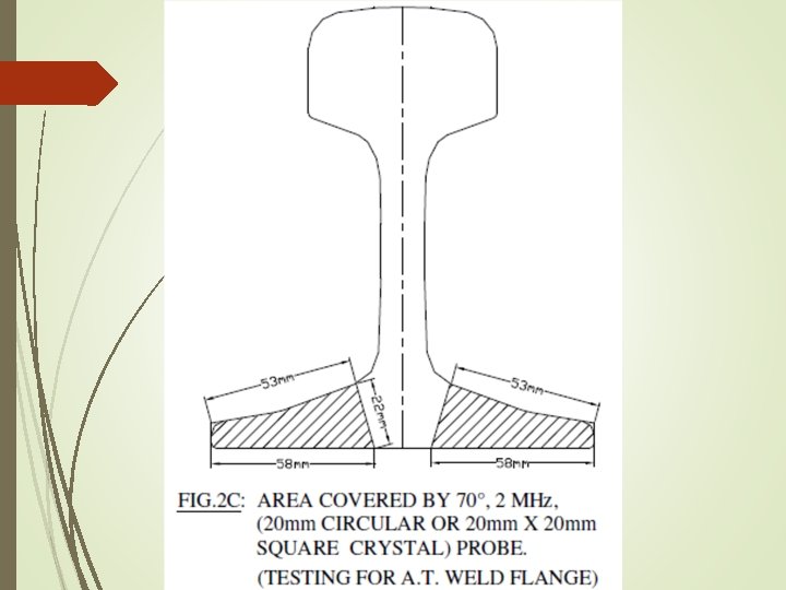
Types of probes 70 ﹾ , 2 MHz probe 20 mm circular (or 20 mm x 20 mm square crystal) Flange & Head testing of AT welds
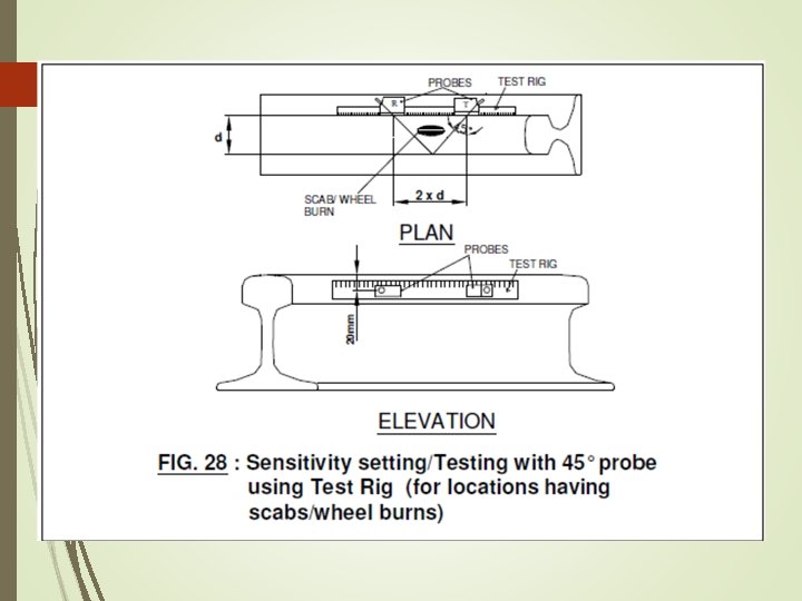
Types of probes 70 ﹾ , 2 MHz Side looking probe (SLP) Half Moon defect in AT welds below web foot junction. Test rig for wheel burnt/scabbed rails For detection of transverse flaws in rail head when rail top surface is having wheel burns/scabs, a test rig with two 45 ﹾ probes sending beam inward shall be used. The distance between probe index marks in the rig shall be adjustable and kept as 134 mm and 145 mm for 52 Kg and 60 Kg rails respectively while testing. For other rail sections this distance can be computed by multiplying rail head width at 20 mm from rail top by 2.
Tandem rig for AT weld testing
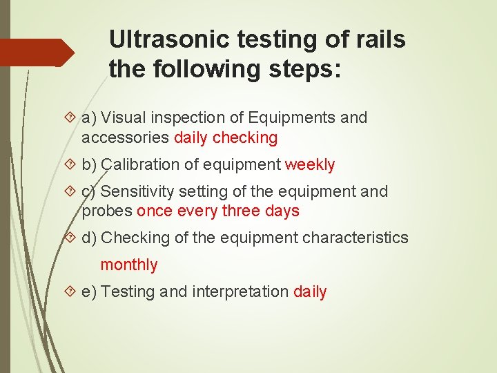
Ultrasonic testing of rails the following steps: a) Visual inspection of Equipments and accessories daily checking b) Calibration of equipment weekly c) Sensitivity setting of the equipment and probes once every three days d) Checking of the equipment characteristics monthly e) Testing and interpretation daily
Checking of equipment characteristics– Monthly check The characteristics of the equipment shall be checked at least once in a month according to IS: 12666 – 88. The following characteristics shall be checked – i) Linearity of time base of flaw detector ii) Linearity of Amplification of flaw detector
Checking of equipment characteristics– Monthly check iii) Penetrative power iv) Resolving power v) Probe Index vi) Beam angle In a month all parameters shall be checked with 0 ﹾ /2 -2. 5 MHz single crystal probe, as per IS: 12666 -88 or its latest version.
Procedure to be followed for adjustment in sensitivity setting on account of variation in rail temperature Following procedure shall be used for adjustments in sensitivity setting of Ultrasonic Rail tester on account of variation in rail temperature before starting the testing of rails. (a) Switch on the Ultrasonic rail tester and keep the equipment for two minutes for thermal acclimatization of the component of the equipment before starting the adjustment in sensitivity setting operation.
Sensitivity setting on account of variation in rail temperature (b) In the Morning at 8. 00 hrs. (i) Normal Probe: Set the sensitivity of the equipment as per procedure and note the gain required to setup the amplitude of the signal to 60% of full screen height. (ii) Angle probe 70 degree (Forward and Backward): Set the sensitivity of the equipment as per procedure and note the gain required to set up the amplitude of the signal to 60% of full screen height.
Sensitivity setting on account of variation in rail temperature (iii)Angle Probe 37 degree (Forward & Backward): Set the sensitivity of the equipment as per procedure and note the gain required to set up the amplitude of the signal to 60% of full screen height. (iv) Note the rail temperature.
Sensitivity setting on account of variation in rail temperature (c) After setting the sensitivity of the probes, the ultrasonic rail tester shall be retained on the standard rail test piece in ON condition and the signal amplitude of individual probe set as per above procedure, shall be checked on hourly basis. If the drop in the signal is observed then the drop shall be compensated by applying extra gain with use of gain control (d. B).
Sensitivity setting on account of variation in rail temperature The height of signal amplitude is maintained to 60% of full screen height. Note the change in rail temperature from rail temperature at 8. 00 Hrs. and corresponding extra gain used.
Sensitivity setting on account of variation in rail temperature (d) Actual Testing: During actual testing on the track, the gain set by the above procedure shall be maintained depending upon the time and rail temperature during testing. Any variation in the signal amplitude shall be compensated by giving measured extra gain (d. B) as per step (c) above to carry out ultrasonic testing.
Sensitivity setting on account of variation in rail temperature (e) Periodicity of setting the sensitivity: The above procedure for sensitivity calibration against temperature variation shall be carried out at least once in a month. The adjustments in sensitivity setting of ultrasonic equipment in respect of gain (d. B) shall be employed accordingly.
Machine Maintenance- Repairs and Half yearly Schedule Maintenance: The manufacturer shall guarantee the satisfactory performance of the entire rail tester system for a period of one year from the date of commissioning of the equipment by the supplier. For proper maintenance after expiry of the guarantee period, railway should make proper arrangements for half yearly repairs of electronic and mechanical parts either under AMC with the manufacturer of the equipment or may develop suitable departmental facilities.
Machine Maintenance- Repairs and Half yearly Schedule Each Zonal railway should create centralised depots for carrying out mechanical repairs and checking the Characteristics of the equipment etc. , at least, once in a month.
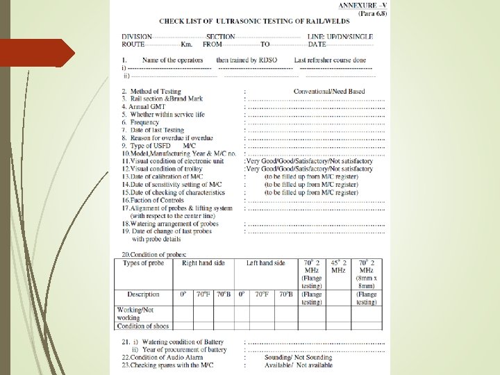
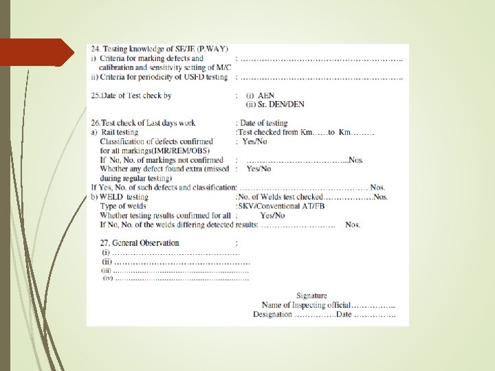
Duties of Sectional ADEN Sectional AEN should spent at least few hours (min. two hours) each month during his routine trolley inspection with USFD team and cross check the working including accuracy/sitting/calibration of USFD machines. In addition, the SE and SSE (in-charge) should also associate themselves occasionally.
Duties of Divisional officers The officer having technical control over the SE/JE (USFD) shall exercise regular checks as per Annexure-VIII of USFD Manual once in between two successive half yearly maintenance schedule carried out in the maintenance depots.
Duties of Divisional officers ANNEXURE-VIII (Para 4. 3. 1) INSPECTION OF RAIL TESTER AND WORK OF PWI (USFD) Name of SE/JE (P. WAY)/USFD, Grade & HQ. Trained by RDSO during. Last course attended at RDSO… MACHINE INSPECTED BY SHRI ………… DATE OF INSPECTION……………….
Duties of Divisional officers 1. MACHINE i) Make and Sr. No. of the machine a) SRT(ECIL/VIBRONICS/EEC/Paras/Others) … b) DRT(EEC/PARAS/Others) ii) Month & Year of procurement of machine iii) Function of controls. (On/Off, Gain, H. Shift, Depth, Energy & Reject etc. )
Duties of Divisional officers iv) Brightness of the machine. (Base line and flaw peaks) v) Working of the junction box. (All terminals) vi) Condition of the probe cables (Connected cables and BNC’s). vii) Condition of probes-0°,
Duties of Divisional officers 70°F & B and 70° 2 MHz, 45° 2 MHz, 70° 2 MHz SLP (with respect to wear & sensitivity) viii) Alignment of probes & lifting system. (With respect of centre line. ) ix) Condition of shoes of probes (Un-even wear). Provision of 0. 2 mm gap. x) Watering arrangements. (Proper and adequate supply to different probes).
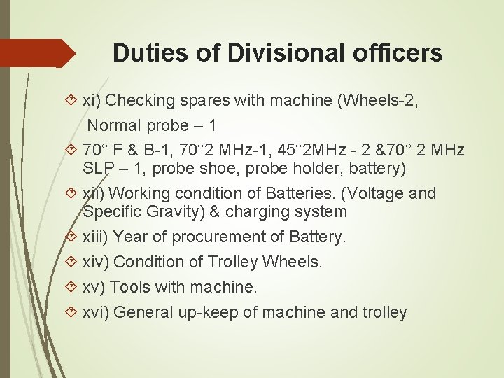
Duties of Divisional officers xi) Checking spares with machine (Wheels-2, Normal probe – 1 70° F & B-1, 70° 2 MHz-1, 45° 2 MHz - 2 &70° 2 MHz SLP – 1, probe shoe, probe holder, battery) xii) Working condition of Batteries. (Voltage and Specific Gravity) & charging system xiii) Year of procurement of Battery. xiv) Condition of Trolley Wheels. xv) Tools with machine. xvi) General up-keep of machine and trolley
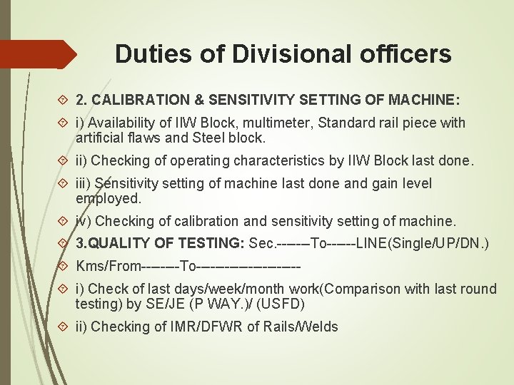
Duties of Divisional officers 2. CALIBRATION & SENSITIVITY SETTING OF MACHINE: i) Availability of IIW Block, multimeter, Standard rail piece with artificial flaws and Steel block. ii) Checking of operating characteristics by IIW Block last done. iii) Sensitivity setting of machine last done and gain level employed. iv) Checking of calibration and sensitivity setting of machine. 3. QUALITY OF TESTING: Sec. -------To------LINE(Single/UP/DN. ) Kms/From----To----------- i) Check of last days/week/month work(Comparison with last round testing) by SE/JE (P WAY. )/ (USFD) ii) Checking of IMR/DFWR of Rails/Welds
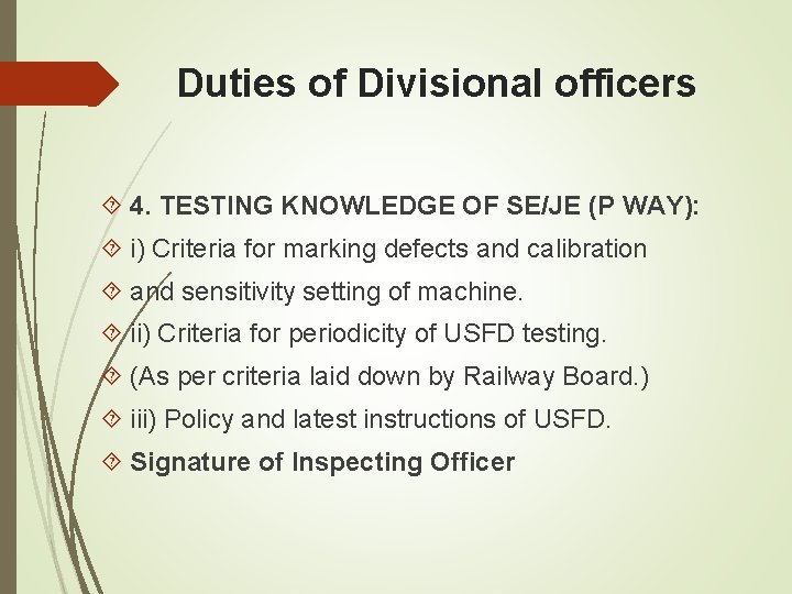
Duties of Divisional officers 4. TESTING KNOWLEDGE OF SE/JE (P WAY): i) Criteria for marking defects and calibration and sensitivity setting of machine. ii) Criteria for periodicity of USFD testing. (As per criteria laid down by Railway Board. ) iii) Policy and latest instructions of USFD. Signature of Inspecting Officer
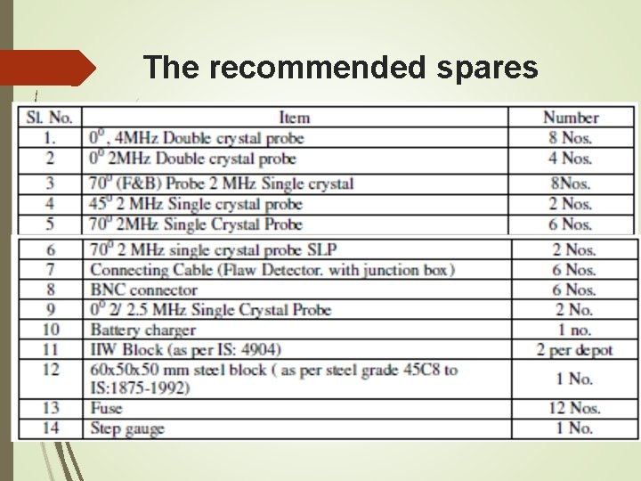
The recommended spares
Defects detectable by different probes a) 0° / Normal probe i) Horizontal split in head due to presence of seams (type 212) ii) Horizontal split in head-web and web foot junction due to presence of rolling seams (type 2321, 2322) iii) Vertical longitudinal split in rail head and web due to presence of internal seams and pipes (type 213, 233) iv) Bolt hole crack (type 135, 235) v) Segregation in head and web junction vi) Flakes (type 1211, 2211) vii) Web-lap (type 239)
Defects detectable by different probes b) 70° angle probe i) Transverse fissure (type 211) due to presence of mostly shatter cracks and some time due heavy inclusions. ii) Transverse cracks originating from surface defects like scab (type 1221, 2221) iii) Wheel burns (type 2251, 2252) iv) Shelling cracks (type 1222, 2222)
Defects detectable by different probes c) 45° angle probe i)Transverse cracks lying below scabs/ wheel burns”
USFD Operations Before Testing (i) Check the battery condition before start of work. Only fully charged battery is to be used during testing. (ii) Check proper functioning of all controls of electronic unit i. e. depth range, gain, reject etc. (iii) Check proper functioning of trolley and probes. (iv) Check junction box, water outlet, probe cable contact and ensure smooth movement of trolley wheels.
USFD Operations Before Testing (v) Maintain proper gap between probing face and probe shoe (0. 2 mm). Check with the help of a feeler gauge. (vi) Check probe alignment by keeping the rail tester on the rail. (vii) Calibrate the instrument weekly as per procedure (viii) Set the equipment for proper sensitivity as per procedure.
USFD Operations During Testing (i) Conduct test as per procedure (ii) Maintain proper alignment of all probes during testing, otherwise false echoes may appear. (iii) Ensure adequate supply of water for coupling. (iv) Check proper functioning of 70° probes by touching the probe bottom with fingers. Noise pattern should appears on the screen. (v) Look out for back wall echo corresponding to normal probe through testing. (vi) Lift the machine at crossings/change of rail table height at joints to protect the probes. (vii) Mark the locations found defective as per classification.
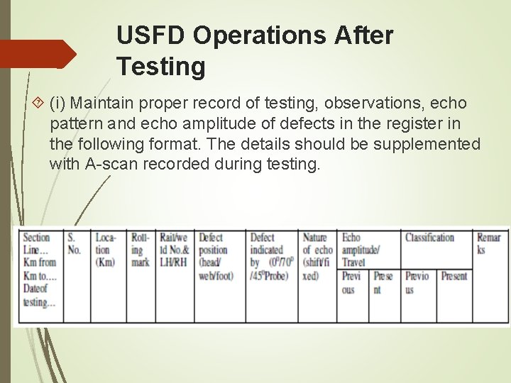
USFD Operations After Testing (i) Maintain proper record of testing, observations, echo pattern and echo amplitude of defects in the register in the following format. The details should be supplemented with A-scan recorded during testing.
USFD Operations After Testing (ii) Charge the battery after every day’s work. IMPORTANT YOUR ULTRASONIC TESTER IS A DELICATE ELECTRONIC EQUIPMENT. TAKE ALL POSSIBLE CARE DURING HANDLING, TRANSPORTATION AND STORAGE TO AVIOD IMPACT, DAMAGE, ETC. LUBRICATE MECHANICAL PARTS PERIODICALLY AND CHARGE BATTERY REGULARLY.
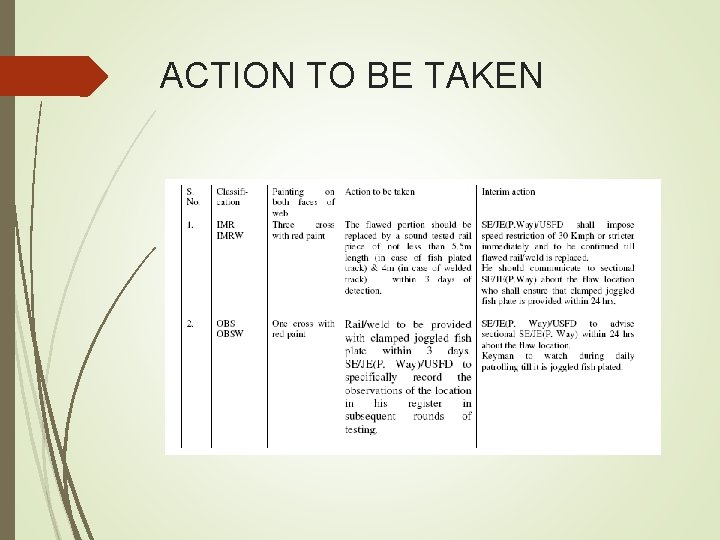
Classification of rail defects However visible defects on rails/ welds shall not be clarified by USFD personal and the same shall be recorded & brought to notice of sectional PWI for further remedial action. Any defect or defect at any location which is detected by two or more probes and are considered to be classified at OBS/OBSW based on peak pattern of individual probe , should be classified as IMR/IMRW and action shall be taken accordingly as per para 6. 4 of USFD Manual.
Classification of rail defects In case two or more OBS/OBSW defects are located within a distance of 4. 0 metre from each other , such OBS/OBSW defects shall be classified as IMR/IMRW and action shall be taken accordingly as per para 6. 4 of USFD Manual.
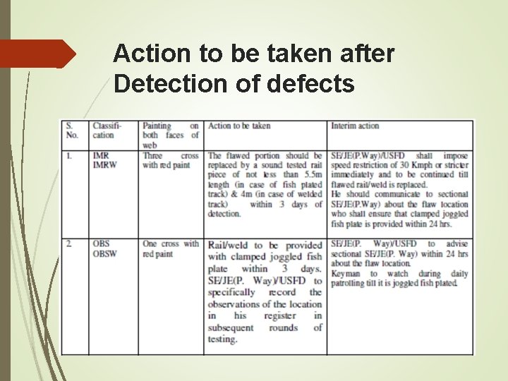
Action to be taken after Detection of defects
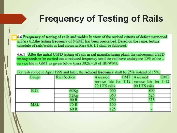
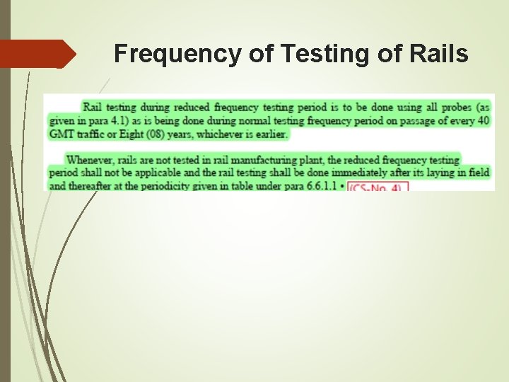
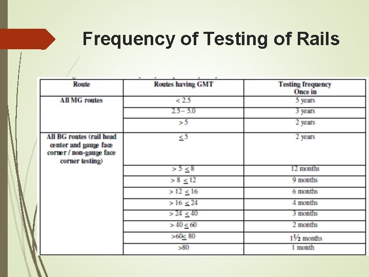
Frequency of Testing of Rails
Frequency of Testing of Rails
Frequency of Testing of Rails
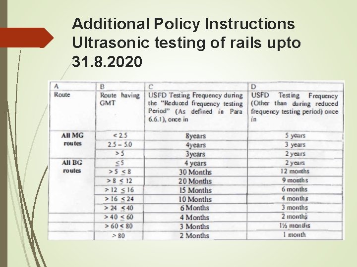
Additional Policy Instructions Ultrasonic testing of rails upto 31. 8. 2020
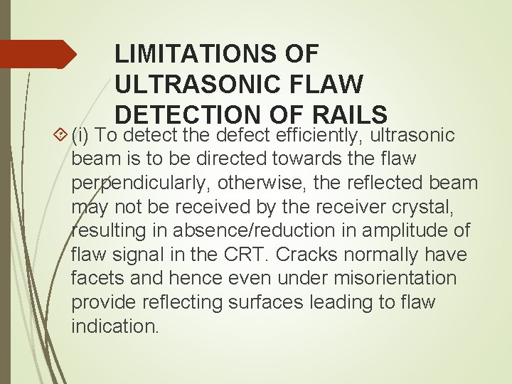
LIMITATIONS OF ULTRASONIC FLAW DETECTION OF RAILS (i) To detect the defect efficiently, ultrasonic beam is to be directed towards the flaw perpendicularly, otherwise, the reflected beam may not be received by the receiver crystal, resulting in absence/reduction in amplitude of flaw signal in the CRT. Cracks normally have facets and hence even under misorientation provide reflecting surfaces leading to flaw indication.
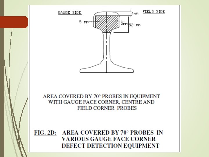
LIMITATIONS OF ULTRASONIC FLAW DETECTION OF RAILS (ii) For detection of defects in rails, probes having incidence angle 0°, 70° (F), 70° (B) have been provided in the USFD trolley. The angles have been chosen in a manner so as to detect defects which are generally observed during service and have been the cause of rail fractures. The section of rail which is scanned by each type of probe has been indicated.
LIMITATIONS OF ULTRASONIC FLAW DETECTION OF RAILS For detection of defects originating from Gauge Face and Non-gauge Face Corner, a dedicated test set-up has been developed. This set-up includes three 70° probes covering approx. the full width of the rail head and a set of two 45° probes. A defect located at 5 mm from the corner is detectable using this equipment. All commonly observed defects in rails are detectable by the above arrangement. In the event of gross misorientation of defect at times it may not be amenable for detection, however such situations are rare.
LIMITATIONS OF ULTRASONIC FLAW DETECTION OF RAILS (iii) Severe pipe in the rail may give indication of flaw echo by 0° probe, But in case of hairline or fine central shrinkage (pipe), negligible drop occurring in bottom signal may remain unnoticed by the USFD operator.
LIMITATIONS OF ULTRASONIC FLAW OF cracks, RAILS 37° probes (iv) For. DETECTION detection of bolt hole are ideal. This is because the cracks emanating from bolt holes are generally oblique and propagate in the zig-zag manner. However, the present SRT/DRT machines have not been provided with 37° probes due to limitation of number of channels and detection of bolt hole cracks is accomplished by normal probe.
LIMITATIONS OF ULTRASONIC FLAW DETECTION OF RAILS These cracks are detectable by 0° probe since they obstruct the path of sound waves and lead to drop/loss of back wall echo. If the cracks are so located that they are unable to be scanned by 0° probes due to smaller size or orientation, such cracks may not be detected in initial stages of their development. ”
LIMITATIONS OF ULTRASONIC FLAW DETECTION OF RAILS (v) If sensitivity of the machine is poor or battery gets discharged the operator may miss the flaw signal. Hence, it is essential to ensure full charging of the battery. (vi) The ultrasonic probes used in the rail testers have a frequency of 4 MHz (longitudinal wave) and 2 MHz (transverse waves). Therefore, cracks lesser than 0. 8 mm size cannot be detected by the present arrangement.
LIMITATIONS OF ULTRASONIC FLAW DETECTION OF RAILS (vii) Rails having rust, pitting, hogging, battering of rail end, misalignment of joints, scabs, wheel burns and other surface imperfections restrict proper acoustic coupling between probe and rail table and may not permit detection of flaws. When ever such defects are encountered, loss of back wall echo or an alarm signal is obtained. This indicates that defects if any below these patches may remain undetected. Under such circumstances hand probing may be done.
LIMITATIONS OF ULTRASONIC FLAW DETECTION OF RAILS Testing of SEJs, points and crossings Due to specific shape on some portion of these components, it is difficult to achieve proper space for acoustic coupling for testing. Therefore testing of these components is to be undertaken as per procedure laid down in chapter 10 & 11.
LIMITATIONS OF ULTRASONIC FLAW DETECTION OF RAILS Testing on sharp curves, gradients, slack gauge etc. The USFD trolley has been designed to operate under normal conditions of gauge. In the event of dimensional variations in the gauge and also at sharp curves it is possible that the probes are not properly contacting the rail surface. This is indicated by loss of backwall echo or also by alarm provided in DRTs for backwall drop. Wherever it is not possible to ensure proper acoustic coupling due to these reasons, testing by hand probing or by single rail tester may be resorted to. Acoustic coupling needs to be ensured under all circumstances to detect the flaws.
LIMITATIONS OF ULTRASONIC FLAW DETECTION OF RAILS Testing with test rig comprising of 45° probes is effective when the sides of rail head are nearly vertical. In case of badly worn faces of rail head the quality of result may not be appropriate. ”
TESTING OF ALUMINOTHERMIC WELDEDRAIL JOINTS Testing of weld head/web, which gets covered during through periodic rail testing by SRT/DRT The frequency of testing in this case is as per Rail frequency. As per this testing defects detected in weld heads are classified as ‘IMRW’ and ‘OBSW’
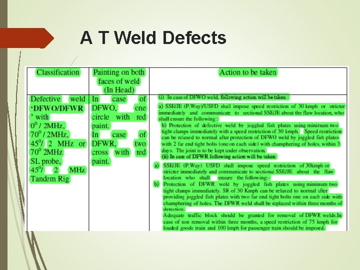
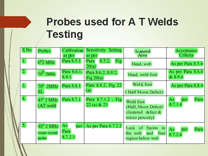
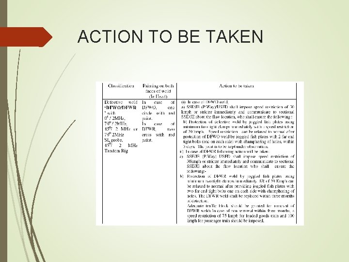
TESTING OF ALUMINOTHERMIC WELDEDRAIL JOINTS Periodic testing of complete weld by hand probing of weld head/web and bottom flange, using 0° 2 MHz, 70° 2 MHz, 45° 2 MHz probe (AT weld foot scanning for half moon shaped defect) and 70° 2 MHz SL probes. The frequency of testing in this case is as per USFD manual Para 8. 15. 1. As per this testing defects detected in welds are classified as ‘DFWO/ DFWR’. The action to be taken for such defective welds
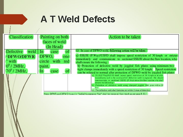
TESTING OF ALUMINOTHERMIC WELDEDRAIL JOINTS Besides this, welds are also tested after their execution using 0° 2 MHz, 70° 2 MHz, 45° 2 MHz probe (AT weld foot scanning for clustered defect/ micro porosities in web foot region) and 45° 2 MHz (Tandem probe scanning for lack of fusion). This test is termed as Initial Acceptance Test. As per this testing, defects detected in welds are classified as ‘DFWO/ DFWR’. The action to be taken for such defective welds
Apparatus required Equipment: Any RDSO approved model of ultrasonic equipment for Alumino thermic welded rail joints as per RDSO specification No. M&C/NDT/129/2005 or its latest version along with rig for tandem testing. Cables: Co-axial cable for each probe shall be used. The length shall not be more than 2. 0 metre. Couplant: soft grease/oil shall be used as couplant
Apparatus required Probes: The following probes having Lead zincronatetitanate crystal shall be used for Ultrasonic testing of Alumino-thermic joints. a) Normal ( 0° ) 2 MHz, 18 mm. f Double crystal. b) 45°/ 2 MHz, 20 mm. dia. or 20 mm. x 20 mm. ( square ) crystal size, Single crystal – 2 no. c) 70°/2 MHz, 20 mm. dia. or 20 mm. x 20 mm. ( square )crystal size, Single crystal - 1 no. d) A pair of two 70°/2 MHz probes inclined at 20 o side looking with respect to usual beam path. Side looking angle of both probes shall be in opposite direction to each other
A T weld Testing General Condition: After execution of AT weld, welded zone shall be dressed properly to facilitate placement of probes and to avoid incidence of spurious signal on the screen. The top of rail head surface shall be dressed to obtain reasonably flat and smooth surface. The flange of the weld up to a distance of 200 mm. on either side of the weld collar shall be thoroughly cleaned with a wire brush to ensure freedom from dust, dirt, surface unevenness etc.
A T weld Testing Visual Examination : All the welded joints shall be cleaned and examined carefully to detect any visible defects like cracks, blow holes. Any joint which shows any visible defect shall be declared defective.
A T Weld Defects
A T Weld Defects
Probes used for A T Welds Testing
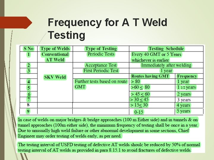
Frequency for A T Weld Testing
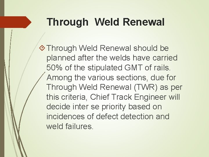
Through Weld Renewal should be planned after the welds have carried 50% of the stipulated GMT of rails. Among the various sections, due for Through Weld Renewal (TWR) as per this criteria, Chief Track Engineer will decide inter se priority based on incidences of defect detection and weld failures.
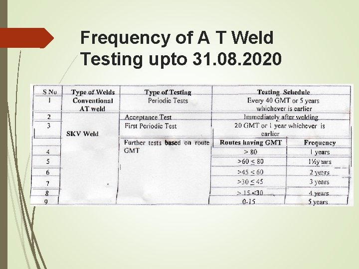
Frequency of A T Weld Testing upto 31. 08. 2020
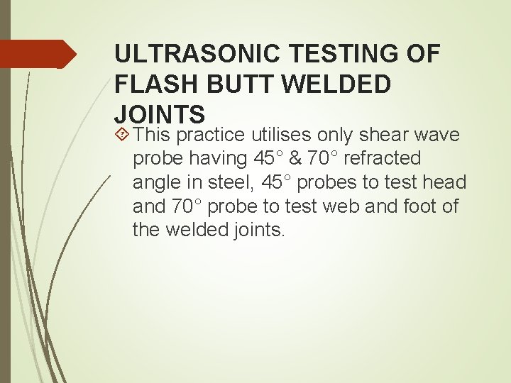
ULTRASONIC TESTING OF FLASH BUTT WELDED JOINTS This practice utilises only shear wave probe having 45° & 70° refracted angle in steel, 45° probes to test head and 70° probe to test web and foot of the welded joints.
Equipment and accessories (i) Any RDSO approved model of ultrasonic equipment for Alumino-thermic welded rail joints as per RDSO specification No. M&C/NDT/129/2005 or its latest version. (ii) Two single crystal 45° 2 MHz probes, one single crystal 70° 2 MHz probe. (iii) 0° 4 MHz double crystal probe (0° 2 MHz single crystal probes, shall be used to check equipment characteristics. ) (iv) Battery with specific voltage suitable for the USFD to be used.
Equipment and accessories (v) Battery charger (vi) Voltmeter (vii) Standard rail piece of 2. 5 m length having standard simulated defects at standard locations (viii) Calibration block 60 X 50 mm of steel grade 45 C 8 to IS : 1875 – 1992. (ix) Steel measuring tape. (x) IIW-VI or V 2 block
Pre-requisite for Flash Butt Welding Coupling condition/surface preparation: The protruding upset metal around welded joint shall be removed by any suitable mechanical means in such a way that the remaining protruded metal does not produce sharp corner and the finished surface of the protruded metal if any left should merge smoothly into the surfaces of the adjacent base metal. The scanning surfaces must be free from weld spatter, scale, dirt, rust and extreme roughness on each side of the weld for a distance equal to 200 mm.
Pre-requisite for Flash Butt Welding Couplant: The couplant should wet the surfaces for the probes and the scanning surfaces and eliminate any air space between the two. Depending upon availability and feasibility of the testing, oil or grease can be used as couplant. Calibrate the depth range of ultrasonic flaw detector with the help of 60 X 50 mm steel block of steel to grade 45 C 8 to IS : 1875 – 92.
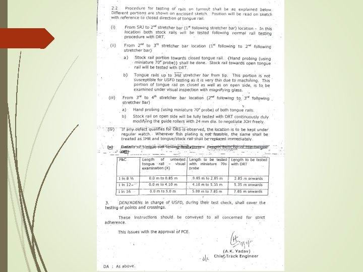
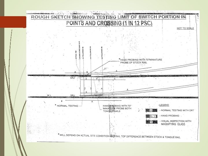
Ultrasonic Testing of Tongue Rail & Stock Rail Equipment: Pulse-echo type ultrasonic flaw detector approved by RDSO. (i) Probes: The rail test trolley shall have following probes made of PZT, barium titanate or similar type of piezo electric crystals: (ii) (a) Double crystal 4 MHz, 18 mm(crystal dia) 0° probe-1 No. fitted in trolley. (b) Single crystal 2 MHz, 20 mm(crystal dia)70° probe- 2 No. fitted in trolley. (c) Single crystal 2 MHz, 20 mm(crystal dia) 70° probe 1 No. for hand probing.
Pre-requisites (i) Battery power: Before undertaking testing, check the power of the battery to ensure that it is fully charged. (ii) Check the correct functioning of the ultrasonic flaw detector on IIW block as per IS: 12666 - 1988. (iii) The couplant should wet the surfaces of the probes and the scanning surfaces properly. Depending upon the availability and feasibility of the testing – water, oil or grease can be used as couplant.
Pre-requisites (iv) Calibrate the depth range of USFD with help of calibration block for 300 mm depth range (longitudinal wave) with the help of 0 o double crystal 4 MHz probe. The equipment is thus calibrated for depth range of 60/30 mm per main scale division for longitudinal wave for equipment having 5/10 main scale div. on horizontal scale.
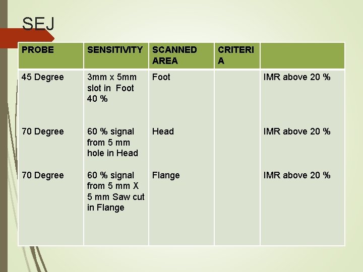
ULTRASONIC TESTING OF SWITCH EXPANSION JOINT Probes: The following probes shall be used for ultrasonic examination of SEJs (i) 0°Normal probe, 18 mm dia. /2 MHz, Double crystal for time scale calibration. (ii) 45°/2 MHz, 20 x 20 mm PZT crystal, Single crystal for locating flaws in middle of web-flange area. (iii) 70°/2 MHz, 20 x 20 mm PZT crystal, Single crystal for locating flaws in nose of the SEJ. (iv) A 60 mmx 50 mm rectangular block of steel to grade 45 C 8 of IS-1875 -1992. Couplant: Water/soft grease/thick oil shall be used as couplant.
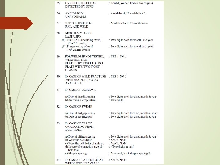
REPORTING AND ANALYSIS OF RAIL/WELD FAILURES All the fractured rail/weld pieces of 150 mm length on each side of fractured face, except those attributable to known extraneous causes such as fractures resulting from accidents, series of fractures resulting from passage of flat wheels, etc. , shall be sent to Chemist and Metallurgist for detailed investigation in the following cases: a) Rail failure within 5 years of primary renewal/Spate of premature rail failures. b) Weld failure within one year of execution. c) Repetitive rail fractures of same rolling mark.
Rail & Weld Failure The Chemist & Metallurgist should submit consolidated investigation report to Headquarters and Director/M&C/RDSO for making out a management information report based on investigation carried out on the above rail failures. The annual briefs made out by RDSO on the analysis of rail fracture must cover these details. Director (M&C) may call for specific samples from Chemist & Metallurgist for confirmation of their findings.
Rail & Weld Failure In the following instances, the samples of rail/weld shall be forwarded to Director/M&C/RDSO. (a) Rail/ weld samples involved in accident/derailment (b) Rail samples of imported origin failed in service within guarantee period.
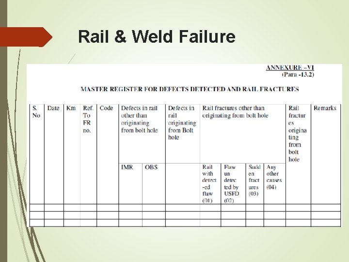
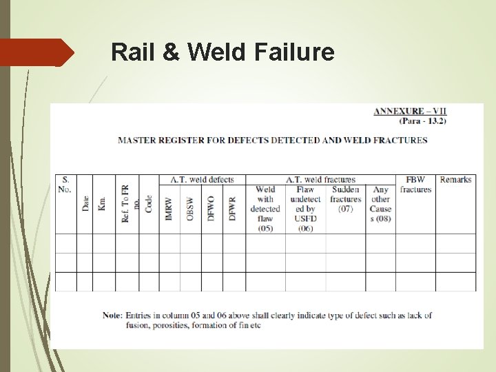
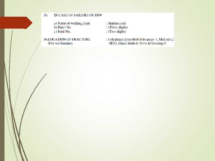
Rail & Weld Failure All the failure reports and defects detected are required to be compiled in the form of Annexure VI & VII at divisional level. Each weld failure shall be analysed by sectional Sr. DEN/DEN, to ascertain whether the failure is sudden, due to impact or inherent defects such as lack of fusion, micro porosities, formation of fin etc. The data including causes, nature and frequency of defects shall be analysed and managerial decisions required for preventive/ corrective action shall be taken promptly.
Rail & Weld Failure
Rail & Weld Failure
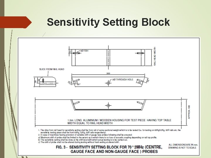
Sensitivity Setting Block
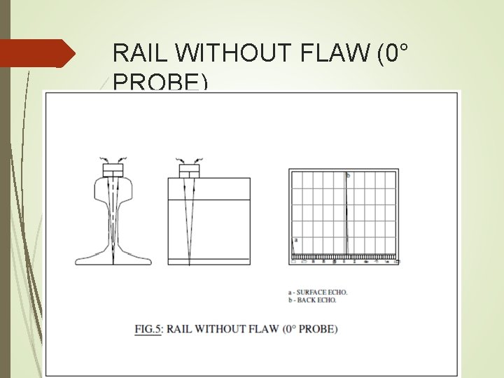
RAIL WITHOUT FLAW (0° PROBE)
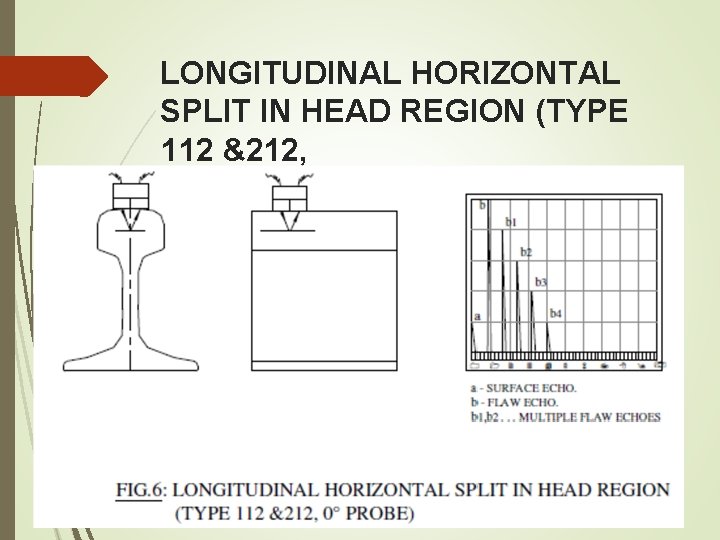
LONGITUDINAL HORIZONTAL SPLIT IN HEAD REGION (TYPE 112 &212, 0° PROBE)
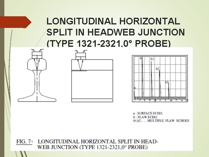
LONGITUDINAL HORIZONTAL SPLIT IN HEADWEB JUNCTION (TYPE 1321 -2321, 0° PROBE)
VERTICAL LONGITUDINAL SPLIT IN HEAD (TYPE 113 & 213, 0° PROBE)
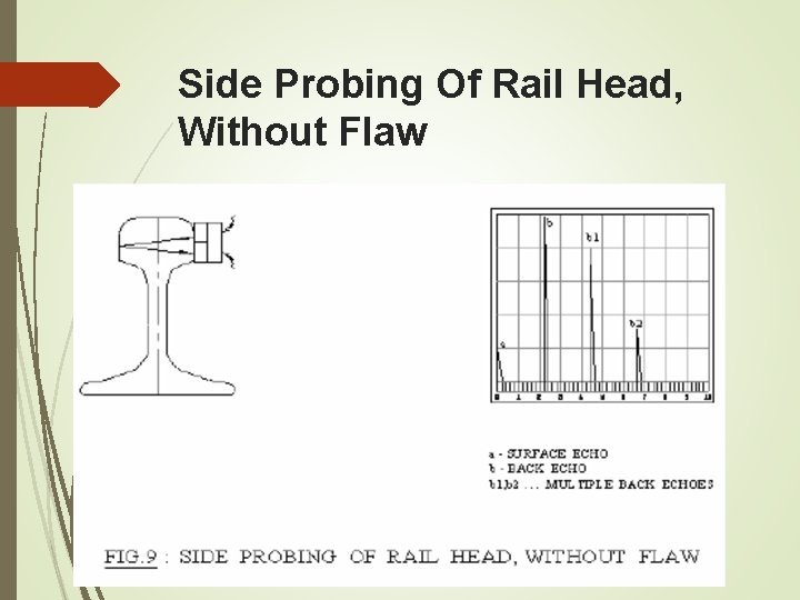
Side Probing Of Rail Head, Without Flaw
VERTICAL LONGITUDINAL SPLIT IN HEAD (0° SIDE PROBING)
Vertical Longitudinal Split in Web (Type 133 & 233 -0° Probe
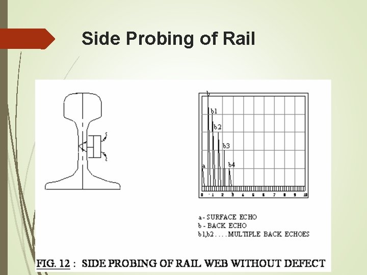
Side Probing of Rail
VERTICAL LONGITUDINAL SPLIT IN WEB (0°SIDE PROBING)
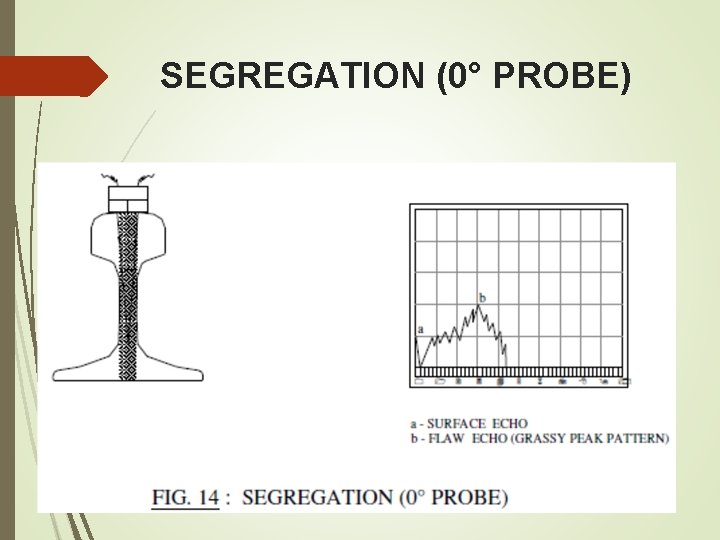
SEGREGATION (0° PROBE)
BOLT HOLE WITHOUT CRACK (0° PROBE)
BOLT HOLE WITH CRACK (TYPE 135, 235, 0° PROBE)
TRANSVERSE DEFECT (TYPE 111, 211 70°, 2 MHz, FORWARD PROBE)
TRANSVERSE DEFECT BY (TYPE 111, 211 70°, 2 MHz, BACKWARD PROBE)
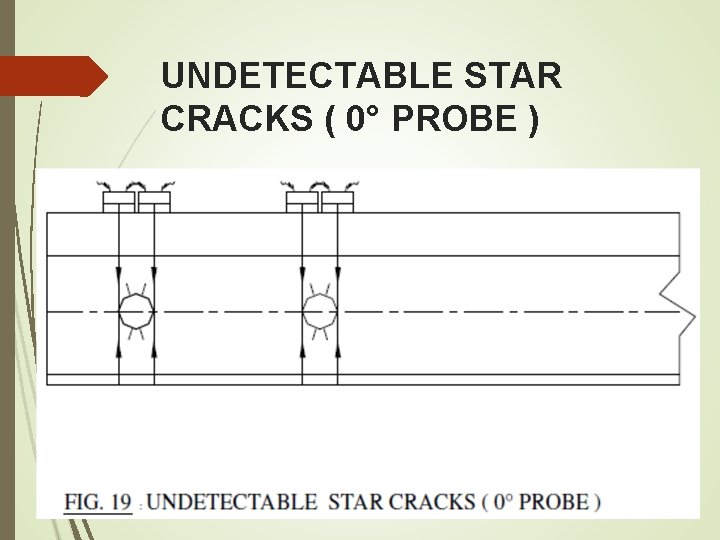
UNDETECTABLE STAR CRACKS ( 0° PROBE )
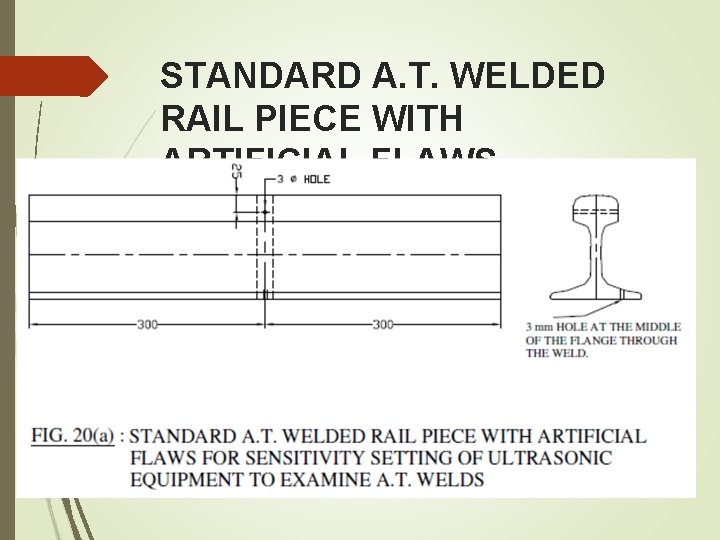
STANDARD A. T. WELDED RAIL PIECE WITH ARTIFICIAL FLAWS
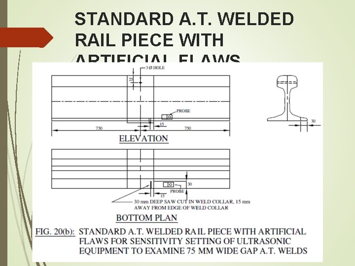
STANDARD A. T. WELDED RAIL PIECE WITH ARTIFICIAL FLAWS
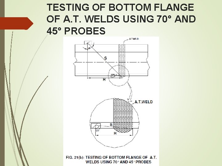
TESTING OF BOTTOM FLANGE OF A. T. WELDS USING 70° AND 45° PROBES
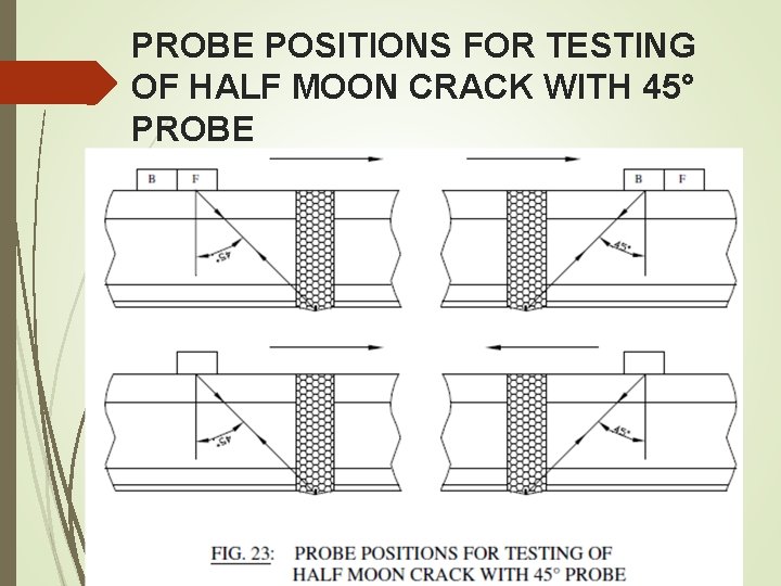
PROBE POSITIONS FOR TESTING OF HALF MOON CRACK WITH 45° PROBE
PROBES USED FOR TESTING OF RAIL AND WELDS
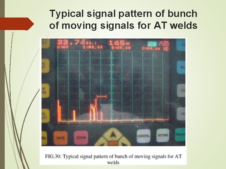
Typical signal pattern of bunch of moving signals for AT welds
THANKS If any suggestions please mail (kathal@iricen. gov. in)
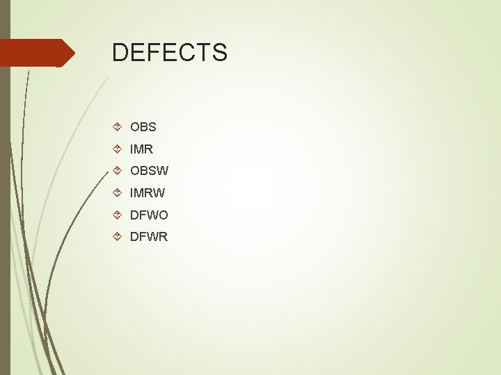
DEFECTS OBS IMR OBSW IMRW DFWO DFWR
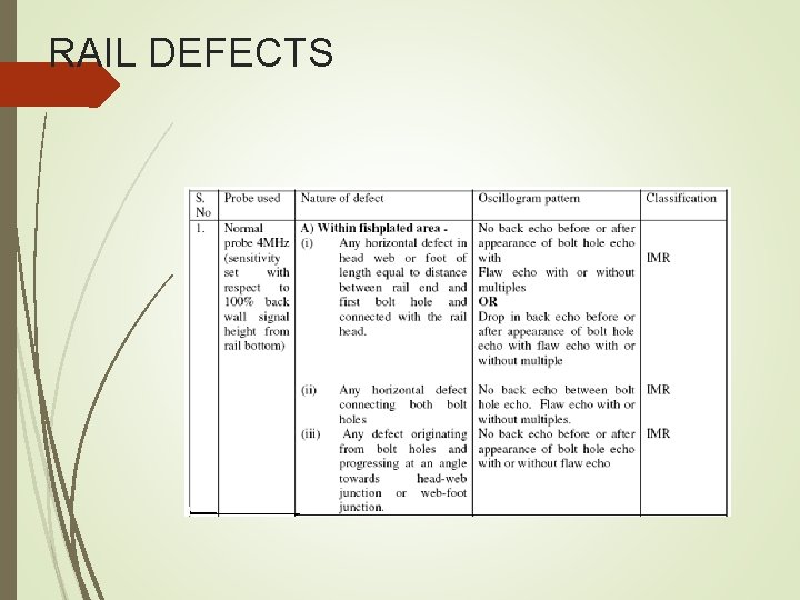
RAIL DEFECTS
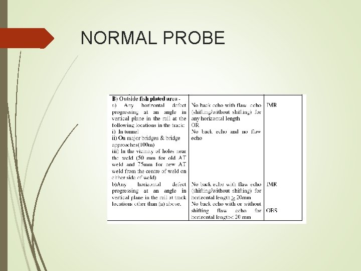
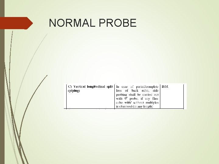
NORMAL PROBE
NORMAL PROBE
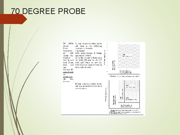
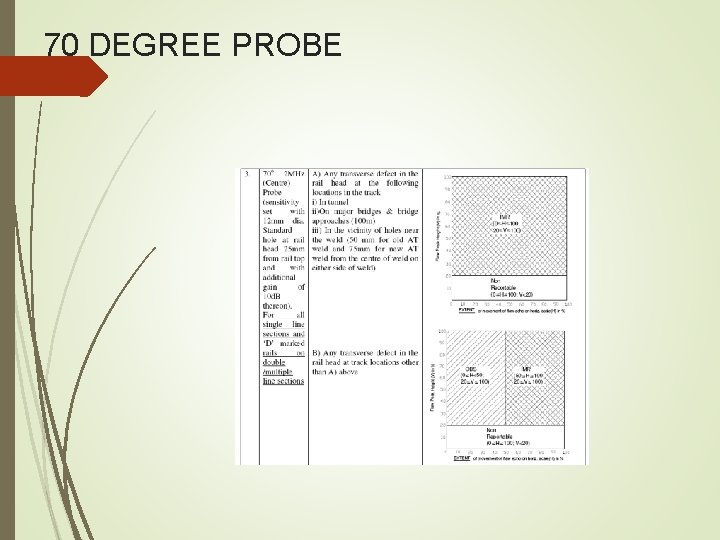
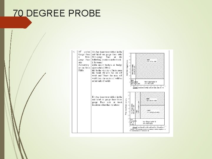
70 DEGREE PROBE
70 DEGREE PROBE
70 DEGREE PROBE
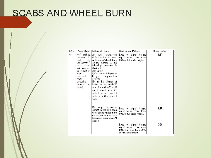
SCABS AND WHEEL BURN
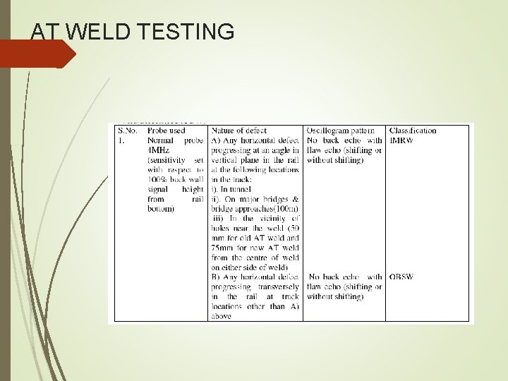
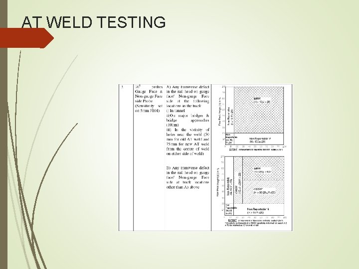
AT WELD TESTING
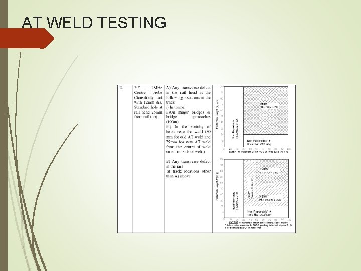
AT WELD TESTING
AT WELD TESTING
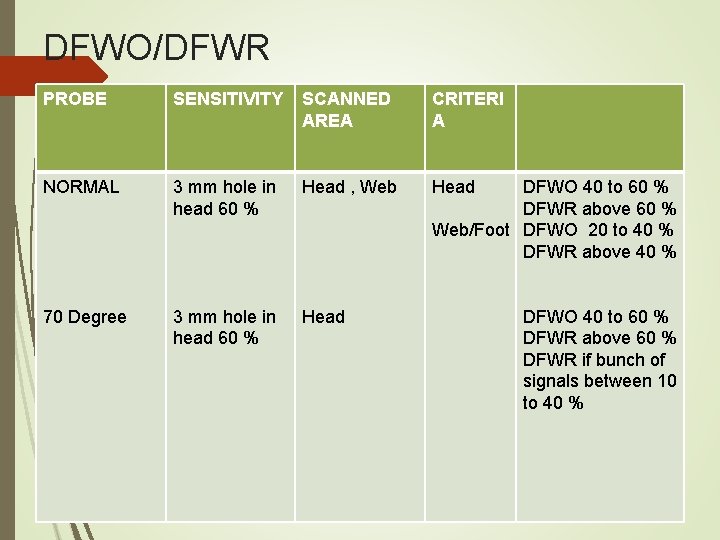
DFWO/DFWR PROBE SENSITIVITY SCANNED AREA CRITERI A NORMAL 3 mm hole in head 60 % Head , Web Head 70 Degree 3 mm hole in head 60 % Head DFWO 40 to 60 % DFWR above 60 % Web/Foot DFWO 20 to 40 % DFWR above 40 % DFWO 40 to 60 % DFWR above 60 % DFWR if bunch of signals between 10 to 40 %
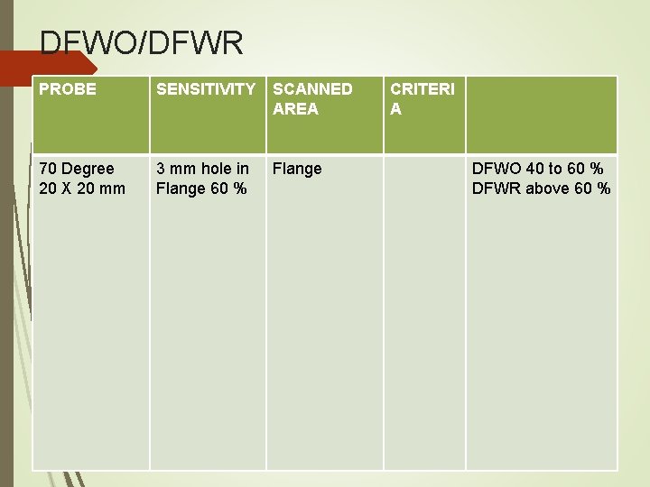
DFWO/DFWR PROBE SENSITIVITY SCANNED AREA 70 Degree 20 X 20 mm 3 mm hole in Flange 60 % Flange CRITERI A DFWO 40 to 60 % DFWR above 60 %
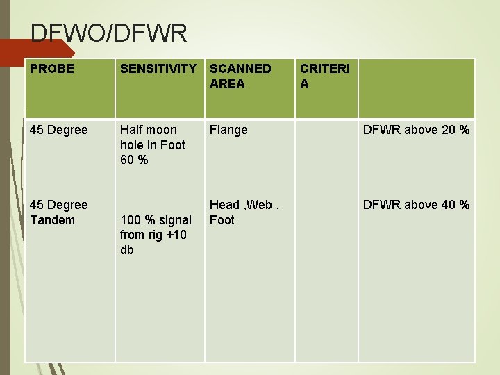
DFWO/DFWR PROBE SENSITIVITY SCANNED AREA 45 Degree Half moon hole in Foot 60 % Flange DFWR above 20 % Head , Web , Foot DFWR above 40 % 45 Degree Tandem 100 % signal from rig +10 db CRITERI A
SEJ PROBE SENSITIVITY SCANNED AREA CRITERI A 45 Degree 3 mm x 5 mm slot in Foot 40 % Foot IMR above 20 % 70 Degree 60 % signal from 5 mm hole in Head IMR above 20 % 70 Degree 60 % signal Flange from 5 mm X 5 mm Saw cut in Flange IMR above 20 %
ACTION TO BE TAKEN
ACTION TO BE TAKEN