Proposal for readout of Forward Detector straw tubes

Proposal for read-out of Forward Detector straw tubes • PANDA DAT requirements • General layout • Prototypes M. Idzik, M. Kajetanowicz, K. Korcyl, G. Korcyl, H. Kuc, A. Misiak, P. Salabura, J. Smyrski, R. Trębacz Krakow Panda group
 • Max drift")
Straw tubes read-out chain Straws: ~ 15000 tubes (6 chambers*8 planes) • Max drift time ~ 150 ns, @ 500 k. Hz max averaged hit rate pile up <10%, -3 ns time resolution 2 • Gain: ~ 2 * 104 FE • Ar (90)/CO 2 (10) mixture FE cards (preamp+ shaper+ discriminator) Sensitivity ~ 3 f. C, noise <1 f. C • based on available ASIC's : CARIOCA or new development based on LUMICAL++ (Marek Idzik) • located on detector frames • differential output (LVDS) Common Clock Distribution TRB Trigger and Read-our Boards- TRB • based on HTDC : time measurement + Time. Over. Threshold for amplidtude meas. • time w. r. t external common clock , 780 ps binning (low resolution-40 MHz clock) • Zero suppression & Hit detection. Slow control interface (i. e EPICS) • data output via GBit optical link Detector Concentrator : Compute Node ATCA standard • several TRB inputs • Detector memory buffer • feature extraction –cluster and tracklet finding i. e based on fired wires numbers and time stamps
 NEED LOT OF ATTENTION")
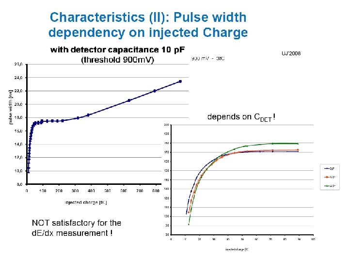
FEE Connection to detector CARIOCA ? ? (not decided, yet) NEED LOT OF ATTENTION !!!! Zdet (f) (f >50 MHz) L/C=370 Cdet = 9 p. F/m (14 -18 p. F)
 connected to straws (UJ october 2008) additional resis.")
FEE Connection to detector FEE (LUMICAL) connected to straws (UJ october 2008) additional resis. ? FEE cards should be electr. shielded !
: 8 channels,")
CARIOCA 10 • CARIOCA (IBM 0. 25 m CMOS 6 SF ): 8 channels, preamp, shaper, BLR, discriminator, differential (LVDS) output: • radiation hardness (checked for LHC requirements: no effects up to 20 Mrad dose) • Sensitivity : at 220 p. F for negative pulse : 2. 3 m. V/f. C • peaking time 14 ns, pulse width 60 ns • power consumption 25 m. W/channel 4 ASIC FEE-UJ’ 2008 CERN -proto
: amplitude as a function of injected charge : CARIOCA 10 gain ~")
Characteristic (I): amplitude as a function of injected charge : CARIOCA 10 gain ~ 2, 6 m. V/f. C TD TR TF
 Sr 90 source no source HV: 1500 V HV: 1400 V")
Carioca+Straw tube (TOT) Sr 90 source no source HV: 1500 V HV: 1400 V • Noise (external pick-up) ~ 8 f. C (status last year) – not satisfactory • New FEE board (better grounding) + em. shielding expected to improve situation
 ~ d.")
Time Over Threshold – energy loss HADES MDC • Signal height (V) ~ d. E/dx Jochen Markert, A. Schmah (GSI) • d. E/dx vs momentum 24 * ~7 mm gaps He: Iso (2: 1) FEE based on ASD 8 chip

Time Over Threshold – energy loss resolution measured by HADES MDC

Garfield simulations for straws one straw average from 20 straws • Ar: CO 2 (90: 10) @ 2 bars • HV 1500 V • charge integration time 100 ns • perpendicular incidence Pions 0. 8 Ge. V/c Protons 0. 8 Ge. V/c ~5 -6%

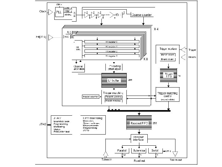
Trigger and Read-out Board ü developed in synergy with ü ü ü HADES experiment 128 channel TDC based on HPTDC optional On-board DAQ functionality via ETRAXFS (LINUX OS 3 200 MHz processors: 100 MBit/s Fast Ethernet interface) Optical Digital link 2 GBit/s) High speed (15 Gb/s) Add. On-connector (32 LVDS) DSP (Tiger. Sharc TS 201) for on-line trigger algorithms/ pre-processing Add. On connector TTL LVDS TTL 100 MBit/s ethernet SDRAM Etrax. FS DSP (TS 201) SDRAM Virtex 4 (LX 40) 2 GBit/s optical link HPTDC Optional HPTDC

The TRBv 2 TDC 2, 3 Optical link SDRAM TDC 0, 1 FPGA Virtex 4 ETRAX SDRAM DSP 4 TDC – 128 channels (~40 ps RMS resolution) FPGA – Virtex 4 LX 40 4 x 512 Mb SDRAM ETRAX FS 100 Mb/s, TCP/IP 2, 5 Gb/s optical link DSP Tiger. Sharc Add. On connector DC/DC converters DC/DC Ethernet Marek Palka, GSI 13
 12")
HUB Conversion from 2 Gb/s 8/10 bit serial transmission to Ethernet protocol (UDP) 12 TRB 16 SFPs (Small Form-factor Pluggable transceivers) optical connectors receive/transmit: ie 12 * 2 Gb/s and 4 * 1 Gb Ethernet Conversion to Ethernet tested (G. Korcyl) FPGA (Lattice SCM 25) with IP core

Expected rates pbeam = 15 Ge. V/c, NInt=2 x 10⁷ s-1.
 T time")
HPTDC working mode with free running clock match. window clock (1 MHz) T time • 1 MHz trigger clock • 1 s matching window (1, 2 s searching window) (T. latency=match. window) • Multiplicty of hit/channel 0. 4 (in window) by 400 k. Hz /wire • hit losses neglegible (concern for >3 MHz/channel) • TDC data: leading & trailing edge : 32 bits(header: TDC id, Event ID, Bunch Id) 32 bits data : TDC id, channel, data 19 bits (pairing mode: 12 bits trailing + 7 bits width) 32 bits(trailer)
 • 128 channels/wire plane : 4 FEE(32 channels each) -")
Data flow estimate (example) • 128 channels/wire plane : 4 FEE(32 channels each) - 1 TRB card (4 x 32 channels HPTDC) • 2. 0 Gbit/s link (250 MByte/s )- total max load (4 links) =1. 0 GByte/s • average maximal load/TRB (1 HPTDC): 13 MHit/s ( 13 hits per trigger/TDC) @ 400 k. Hz rate/wire • 13 MHits*10 Bytes(hit=trailing + falling edge) = 130 MByte/s 4 links (1 GByte/s) to Compute Nodes TRB FEE x 8 (wire planes) O degree plane Left (L) wire plane O degree plane Right (R)

• back-up slides
 ASIC gain")
Characteristics : Amplitude as a function of injected charge: Lumi. Cal (AGH) ASIC gain ~ 13 m. V/f. C
 X- ray source 55 Fe • HV")
Pulses from detector in LUMIVAL (Rf mode) X- ray source 55 Fe • HV = 1200 V • HV = 1350 V full absorption shape changes because of amplitude saturation after X-ray escape Pulses from iron source 55 Fe, in gas mixture 90% Ar 10% CO 2 Visible differences between pulses from escape peak and main peak, At picture on the right side pulses saturation of large pulses is visible

Cosmic rays: straw tube with Lumi. Cal chip and ADC with gate signal from scintillating detector 90 noise peak , generated because of larger scintillator area as compared to straw tube 80 70 counts 60 50 40 30 20 10 0 0 100 200 300 channel HV =1300 V, gas mixture 90% Ar 10% CO 2 400 500

Detector and DAT requirements • interaction rate: 20 MHz • lack of ONE SPECIFIC hardware trigger signal • raw data flow: 40 - 80 GB/s • continuously sampling FE (time stamps) • typ. event size: 4 – 8 k. B • flexibility in the choice of triggering algorithms
 2 alternative options considered so far (K. Korcyl")
PANDA DAT architecture (one possible choice) 2 alternative options considered so far (K. Korcyl ) 1. push and pull 2. „push only”
 VME CPU CTS to the front end electronics TRB")
The HADES DAQ (>100 TRBs!) VME CPU CTS to the front end electronics TRB + MDC Add. On TRB + General purpose Add. On TRB + TOF Add. On TRB + Shower Add. On LVL 1 Trigger box TRB + RICH Add. On TRB for RPC TRB for Time Wall, Start, Veto TRBnet. . . TRB + HUB Add. On Ethernet Parallel Event Building (computers) 24

HPTDC features ü Used in many HEP experiments. Developed at CERN, produced in IBM technology 0. 25 m CMOS (ibm) ü 32 channels multihit TDC with variable resolution: 785 ps, 195 ps, 98 ps, 25 ps (LSB) - measurement wrt. free running clock, self calibration, double pulse resolution typ. 5 ns ü Max hit rate/channel 2 MHz, Trigger rates up to 1 MHz @40 MHz clock ü Internal buffer to story hits (max 256 hits/8 channel)- buffer BUT with 4 deep derandomizer in each channel ü individual registration of leading and trailing edges inside internal chip buffers- Time over Threshold ü Two operation modes: A: TRIGGER MATCHING disabled. The raw time measurements from input channels are passed unchanged to the read-out fifo and can be readout to external buffers. 40 MHz read-out B. TRIGGER MATCHING enabled. Hits inside pre-programmed window are filtered. Latencies <50 s High rates->low latencies

HPTDC hit losses hit rate 25 ns dead time reduces loss by factor 10 at 3 MHz rate
- Slides: 27