
PROPERTYBASED MONITORING OF ANALOG AND MIXEDSIGNAL SYSTEMS J
PROPERTY-BASED MONITORING OF ANALOG AND MIXED-SIGNAL SYSTEMS J. HAVLICEK 1, S. LITTLE 1, O. MALER 2 AND D. NICKOVIC 3 1 FREESCALE 2 VERIMAG 3 IST AUSTRIA
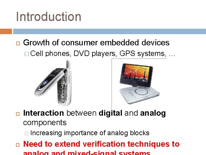
Introduction Growth of consumer embedded devices � Cell phones, DVD players, GPS systems, … Interaction between digital and analog components � Increasing importance of analog blocks Need to extend verification techniques to
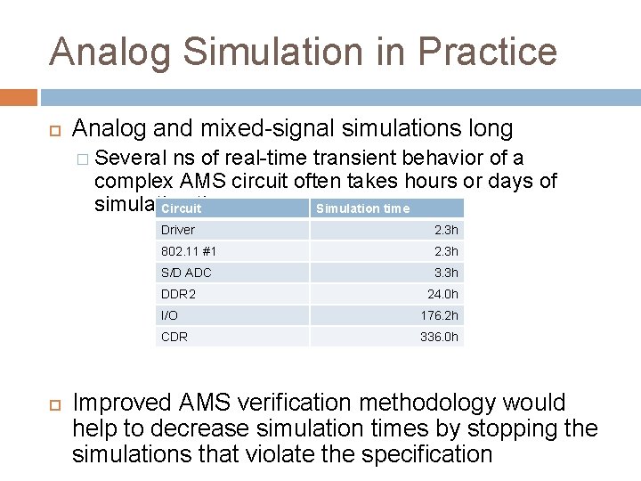
Analog Simulation in Practice Analog and mixed-signal simulations long � Several ns of real-time transient behavior of a complex AMS circuit often takes hours or days of simulation Circuittime Simulation time Driver 2. 3 h 802. 11 #1 2. 3 h S/D ADC 3. 3 h DDR 2 24. 0 h I/O 176. 2 h CDR 336. 0 h Improved AMS verification methodology would help to decrease simulation times by stopping the simulations that violate the specification
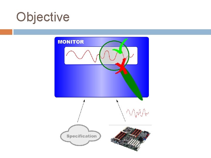
Objective
Other Applications Monitoring of the physical systems � Our focus is on simulated models � Post-production quality tests in chips, detecting undesirable situations in nuclear and industrial plants, detecting violations of procedures in an organization… Real-time embedded systems Monitoring the medical devices
Overview Property-based verification in digital context Verification and validation in AMS context Property-based monitoring of AMS systems � STL specification language � Algorithms for checking properties � Tool for monitoring properties of AMS systems � Case studies Industrial perspective and requirements � What is missing for industrial applications of the framework? � Development of ASVA specification language Summary
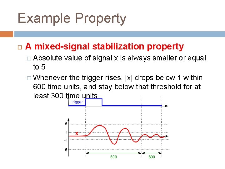
Example Property A mixed-signal stabilization property � Absolute value of signal x is always smaller or equal to 5 � Whenever the trigger rises, |x| drops below 1 within 600 time units, and stay below that threshold for at least 300 time units
Systems and Properties System: a dynamic mathematical model that generates behaviors Property: a set of expected (“good”) behaviors that the system should exhibit A system satisfies a property, if all the behaviors that it generates are included in the set of behaviors defined by the property
Properties in Verification: Digital Setting System: a mathematical model of the digital system � Finite state machines and automata Property: set of expected behaviors expressed in a rigorous specification language Formal verification and model-checking � Exhaustive “simulation” of the digital system model Monitoring of simulation-traces � Incomplete but effective verification technique
Property Specification Languages Temporal logics and regular expressions � Linear temporal logic (LTL), Computation-tree logic (CTL), Regular expressions… � Concise languages with precise semantics Specification languages in industry � System. Verilog Assertions (SVA), Property Specification Language (PSL) � Combine LTL and regular expressions � Industrial standards (IEEE) � Sugar: clocks, local variables…
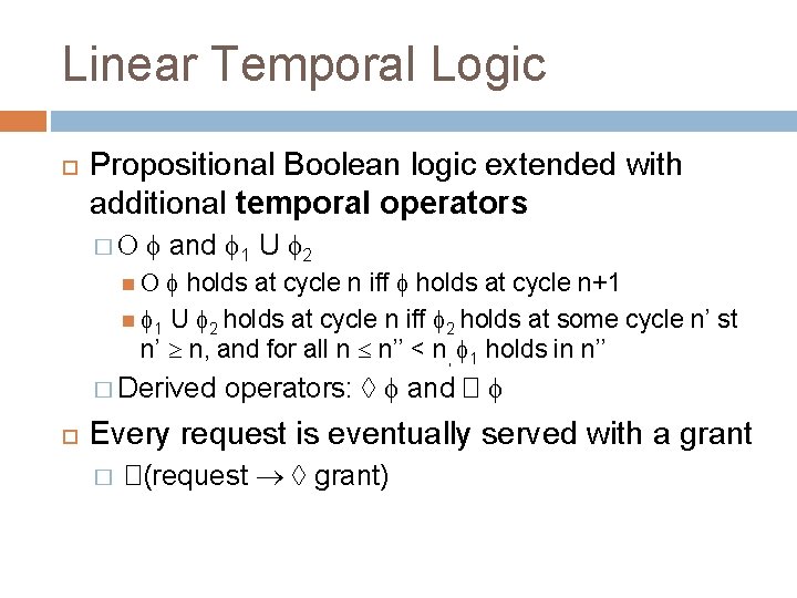
Linear Temporal Logic Propositional Boolean logic extended with additional temporal operators � and 1 U 2 holds at cycle n iff holds at cycle n+1 1 U 2 holds at cycle n iff 2 holds at some cycle n’ st n’ n, and for all n n’’ < n, 1 holds in n’’ � Derived operators: and � Every request is eventually served with a grant � �(request grant)

System. Verilog Assertions Why not use LTL in industry? Need for specific constructs that facilitate specification of designs by verification engineers and tight integration with the simulators SVA – IEEE standard � Integral part of System. Verilog � Includes the specific requirements from industrial users
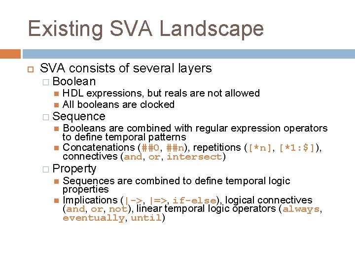
System. Verilog Assertions SVA consists of several layers � Boolean HDL expressions, but reals are not allowed All booleans are clocked � Sequence Booleans are combined with regular expression operators to define temporal patterns Concatenations (##0, ##n), repetitions ([*n], [*1: $]), connectives (and, or, intersect) � Property Sequences are combined to define temporal logic properties Implications (|->, |=>, if-else), logical connectives (and, or, not), linear temporal logic operators (always, eventually, until)
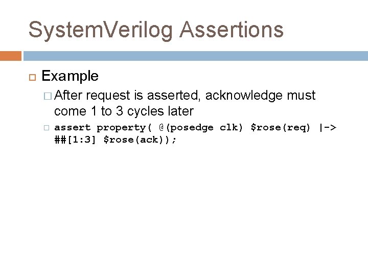
System. Verilog Assertions Example � After request is asserted, acknowledge must come 1 to 3 cycles later � assert property( @(posedge clk) $rose(req) |-> ##[1: 3] $rose(ack));
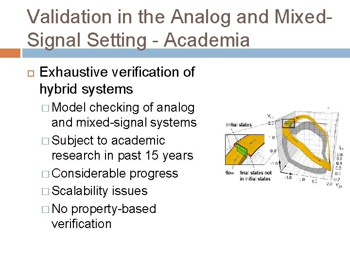
Validation in the Analog and Mixed. Signal Setting - Academia Exhaustive verification of hybrid systems � Model checking of analog and mixed-signal systems � Subject to academic research in past 15 years � Considerable progress � Scalability issues � No property-based verification
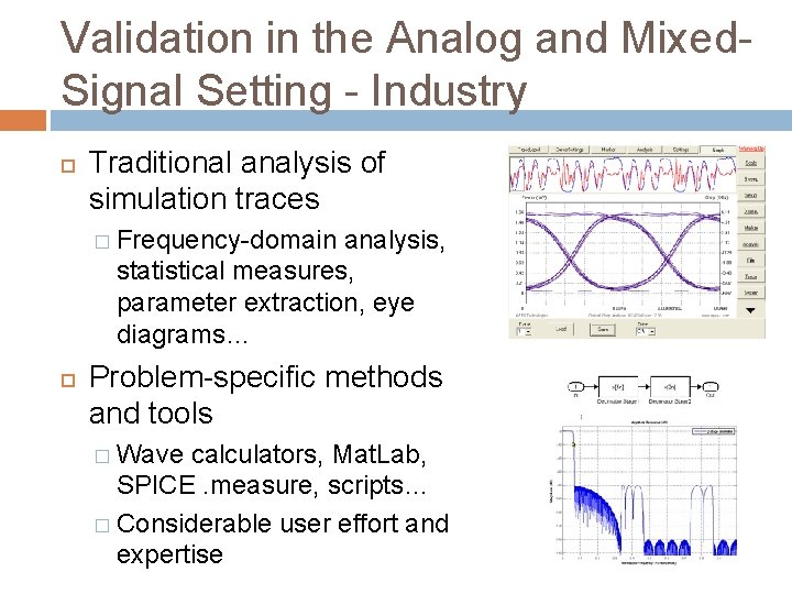
Validation in the Analog and Mixed. Signal Setting - Industry Traditional analysis of simulation traces � Frequency-domain analysis, statistical measures, parameter extraction, eye diagrams… Problem-specific methods and tools � Wave calculators, Mat. Lab, SPICE. measure, scripts… � Considerable user effort and expertise
Validation in the Analog and Mixed. Signal Setting - Industry State-of-the-art in industry is a bit ad hoc � AMS designers are not well versed in digital verification methodologies � AMS tools and methodologies are not mature Working chips are being built � Test chips help validate circuit correctness � Incremental design changes reduce risk � Ad hoc verification methods still find bugs Bugs are often found in the mixed-signal interface or digital control of analog circuits
Industrial examples Analog designers are responsible for verifying most of the block-level details using traditional analog verification methodologies AMS verification at the block level focuses on the interfaces and digital control AMS verification at the So. C level is becoming increasingly important � Interaction between analog and digital blocks is becoming more complex
PMU: Model creation Power management unit (PMU) � AMS block with an asynchronous digital interface controlling several voltage/current supplies that are switched on/off in various power modes Create an abstract PMU model (100% manual process) � Digital components are translated to RTL � Critical behavior of analog components is extracted and modeled using Verilog-AMS Relate abstract model to schematic to check accuracy � State of the art method is co-simulation of critical scenarios � Assertions check that deviations between the models are within acceptable tolerances
PMU: Block-level verification Functional verification of abstract model � Combination of Verilog-AMS/System. Verilog creates the stimulus and does the checking � For example: a Verilog-AMS monitor digitizes the result of an AMS check for use in an assertion Spot check schematic behaviors for sanity �A subset of critical scenarios are checked � Swapping models isn’t always trivial � Checkers will likely have to be updated (schematic outputs are not as “clean” as model outputs, checkers may reference internal model variables, etc. )
PMU: So. C-level verification PMU is critical for So. C-level verification � Verifying start-up and power mode transitions is a critical So. C verification task � Abstract model used to meet performance requirements � Schematic may be used for a small number of high priority scenarios
PLL Most PLLs are largely digital logic Use same verification methodology as the PMU AMS verification focuses on digital interface and system integration issues AMS verification is not well equipped to verify frequency domain properties (e. g. , phase noise) � These are still done by the analog designer
Bridging the gap between digital and analog validation Specification component of digital verification can be successfully exported to analog and mixed-signal systems Specification language adapted to continuous and mixed-signal behaviors Automatic monitoring of analog and mixedsignal simulation traces wrt the specifications
PROPERTY-BASED MONITORING OF AMSSYSTEMS: AN ACADEMIC FRAMEWORK
Overview Monitoring of timed and continuous signals � Signal temporal logic STL for expressing properties of continuous and hybrid behaviors Dense-time temporal logic MITL + numeric predicates � Two procedures for monitoring simulation traces against STL properties Offline + Incremental � AMT tool � Case studies FLASH memory and DDR 2 memory interface
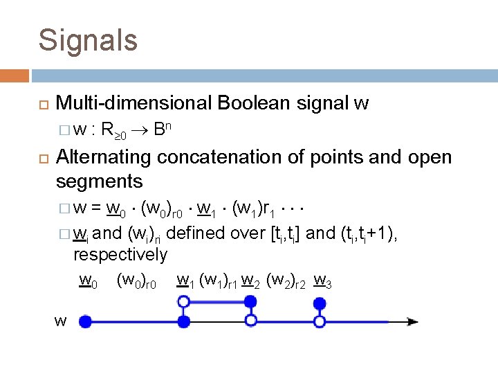
Signals Multi-dimensional Boolean signal w �w : R 0 Bn Alternating concatenation of points and open segments = w 0 (w 0)r 0 w 1 (w 1)r 1 � wi and (wi)ri defined over [ti, ti] and (ti, ti+1), respectively �w w 0 w (w 0)r 0 w 1 (w 1)r 1 w 2 (w 2)r 2 w 3
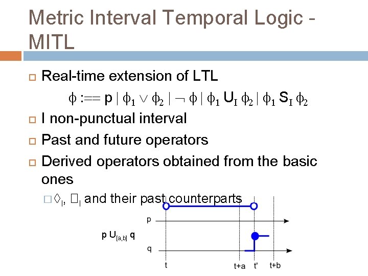
Metric Interval Temporal Logic MITL Real-time extension of LTL : == p | 1 2 | | 1 UI 2 | 1 SI 2 I non-punctual interval Past and future operators Derived operators obtained from the basic ones � I , �I and their past counterparts p U[a, b] q
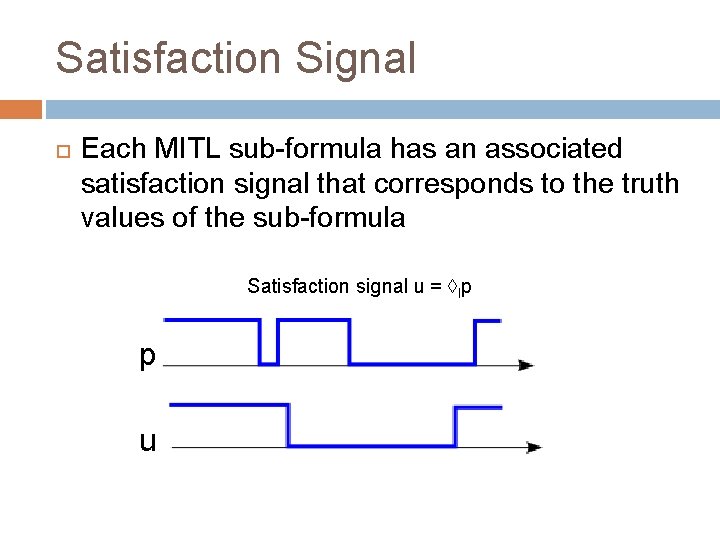
Satisfaction Signal Each MITL sub-formula has an associated satisfaction signal that corresponds to the truth values of the sub-formula Satisfaction signal u = Ip p u
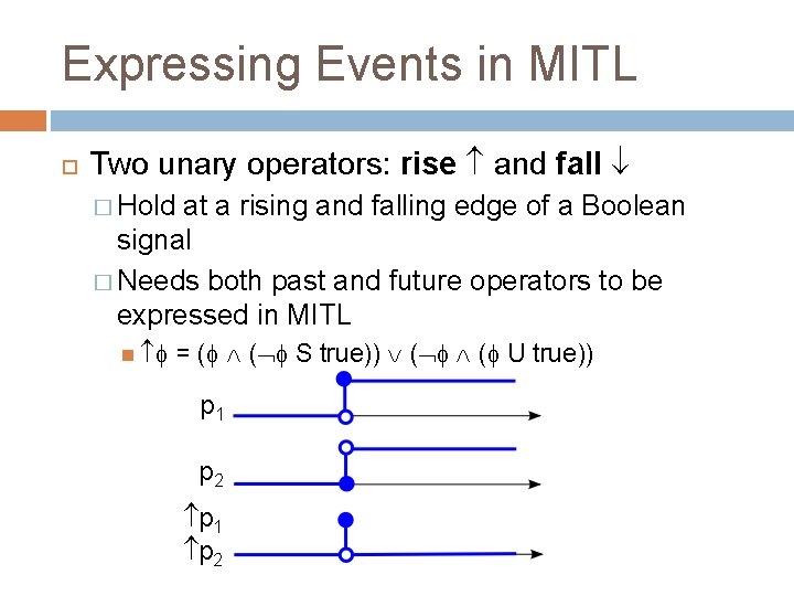
Expressing Events in MITL Two unary operators: rise and fall � Hold at a rising and falling edge of a Boolean signal � Needs both past and future operators to be expressed in MITL = ( ( S true)) ( ( U true)) p 1 p 2
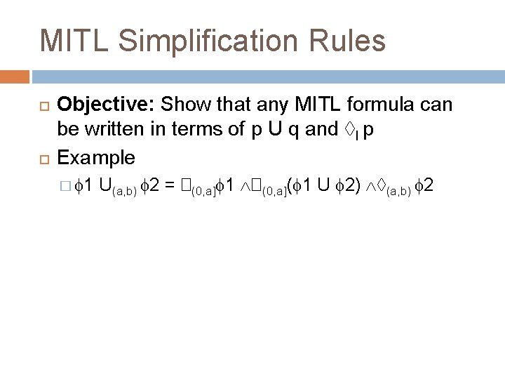
MITL Simplification Rules Objective: Show that any MITL formula can be written in terms of p U q and I p Example � 1 U(a, b) 2 = �(0, a] 1 �(0, a]( 1 U 2) (a, b) 2
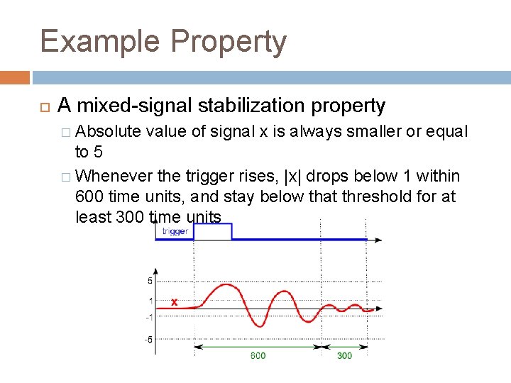
Example Property A mixed-signal stabilization property � Absolute value of signal x is always smaller or equal to 5 � Whenever the trigger rises, |x| drops below 1 within 600 time units, and stay below that threshold for at least 300 time units
)](http://slidetodoc.com/presentation_image_h/b620cebe1726103d384bd570d92a77eb/image-32.jpg "Example Property �((|x| 5) ( trigger [0, 600]�[0, 300](|x| 1))")
Example Property �((|x| 5) ( trigger [0, 600]�[0, 300](|x| 1))
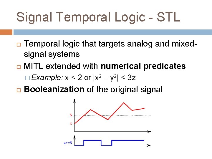
Signal Temporal Logic - STL Temporal logic that targets analog and mixedsignal systems MITL extended with numerical predicates � Example: x < 2 or |x 2 – y 2| < 3 z Booleanization of the original signal
Monitoring STL Properties Marking: a procedure that computes the satisfaction signal of each sub-formula of an STL specification � Doubly-recursive procedure, on time and the structure of the formula � Procedure directly applied on signals, no automata Two algorithms for checking STL properties � Offline marking: input is fully available � Incremental marking: input is dynamically observed
 � [1, 3](x 5)](http://slidetodoc.com/presentation_image_h/b620cebe1726103d384bd570d92a77eb/image-35.jpg "Offline Marking: Overview 5 x x 5 [1, 3](x 5) � [1, 3](x 5)")
Offline Marking: Overview 5 x x 5 [1, 3](x 5) � [1, 3](x 5) 0 2 4 6 8
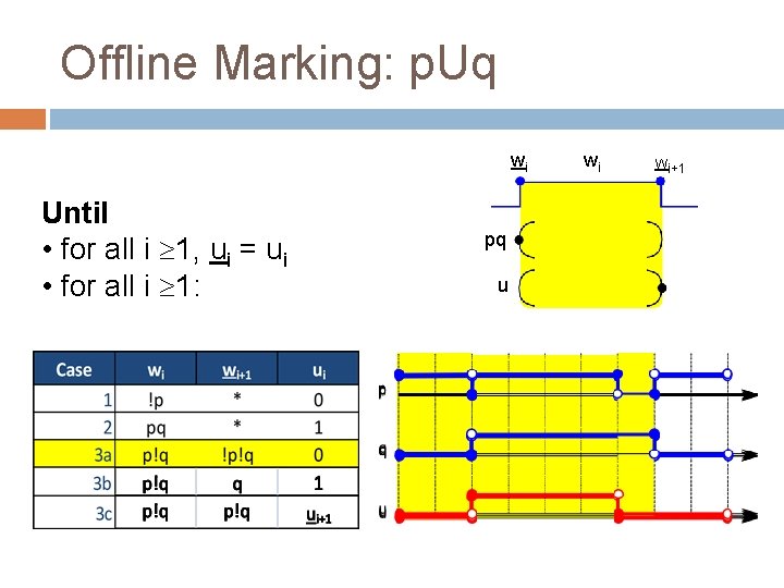
Offline Marking: p. Uq wi Until • for all i 1, ui = ui • for all i 1: pq u wi Wi+1
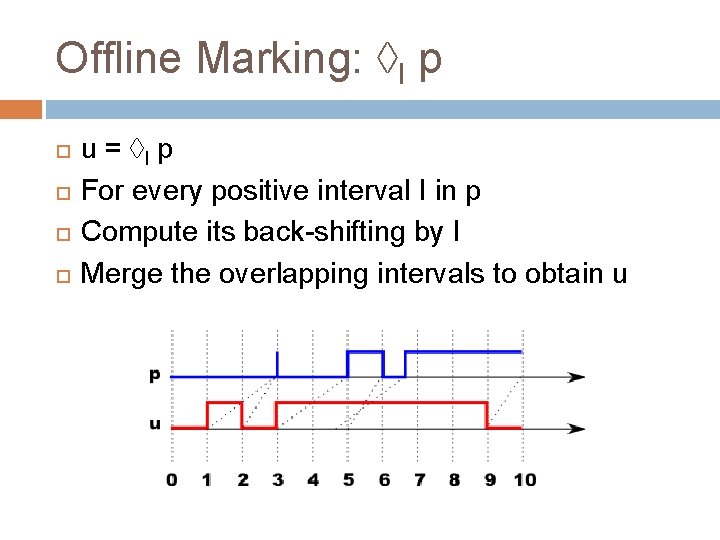
Offline Marking: I p u = I p For every positive interval I in p Compute its back-shifting by I Merge the overlapping intervals to obtain u
 � [1, 3](x 5)](http://slidetodoc.com/presentation_image_h/b620cebe1726103d384bd570d92a77eb/image-38.jpg "Incremental Marking: Overview 5 x x 5 [1, 3](x 5) � [1, 3](x 5)")
Incremental Marking: Overview 5 x x 5 [1, 3](x 5) � [1, 3](x 5) 0 2 4 6 8
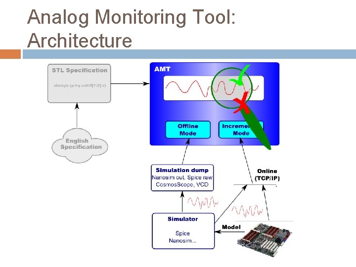
Analog Monitoring Tool: Architecture
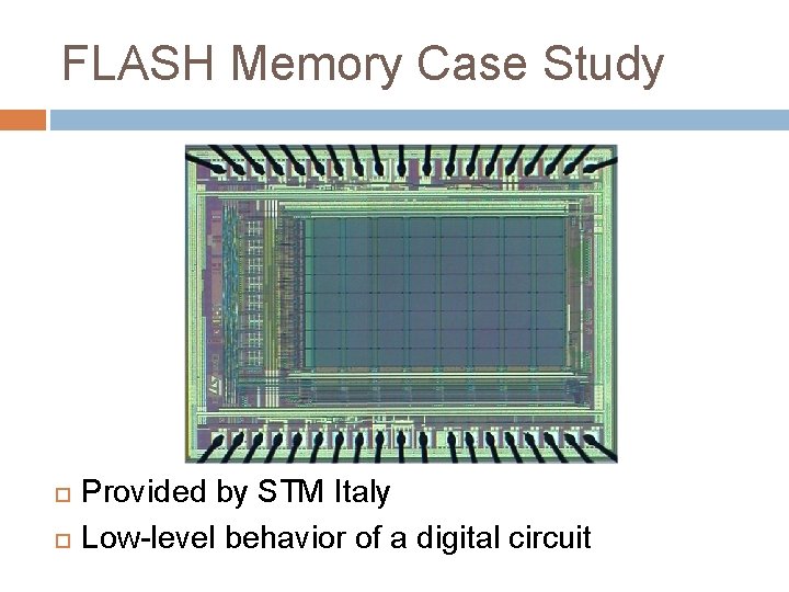
FLASH Memory Case Study Provided by STM Italy Low-level behavior of a digital circuit
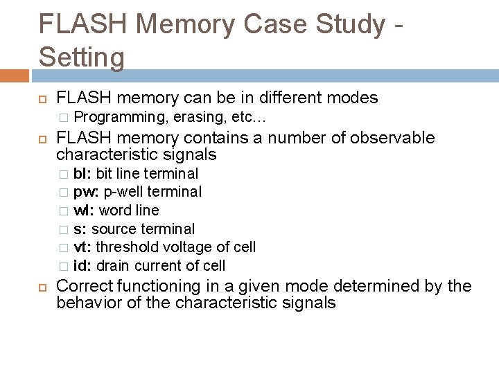
FLASH Memory Case Study Setting FLASH memory can be in different modes � Programming, erasing, etc… FLASH memory contains a number of observable characteristic signals bl: bit line terminal � pw: p-well terminal � wl: word line � s: source terminal � vt: threshold voltage of cell � id: drain current of cell � Correct functioning in a given mode determined by the behavior of the characteristic signals
FLASH Memory Case Study Properties STM engineers provided 4 properties that specify the expected behavior of characteristic signals of the FLASH memory � 3 properties about the FLASH memory in the programming and 1 in the erasing mode Several iterations needed to translate the intended meaning of the English specifications into STL properties
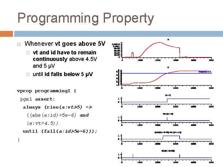
Programming Property Whenever vt goes above 5 V � vt and id have to remain continuously above 4. 5 V and 5 μV � until id falls below 5 μV vprop programming 1 { pgm 1 assert: always (rise(a: vt>5) -> ((abs(a: id)>5 e-6) and (a: vt>4. 5)) until (fall(a: id>5 e-6))); }
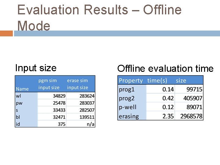
Evaluation Results – Offline Mode Input size Offline evaluation time
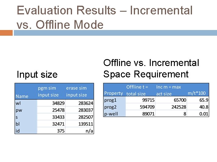
Evaluation Results – Incremental vs. Offline Mode Input size Offline vs. Incremental Space Requirement
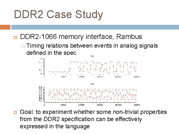
DDR 2 Case Study DDR 2 -1066 memory interface, Rambus � Timing relations between events in analog signals defined in the spec Goal: to experiment whether some non-trivial properties from the DDR 2 specification can be effectively expressed in the language
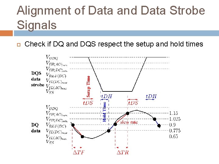
Alignment of Data and Data Strobe Signals Check if DQ and DQS respect the setup and hold times
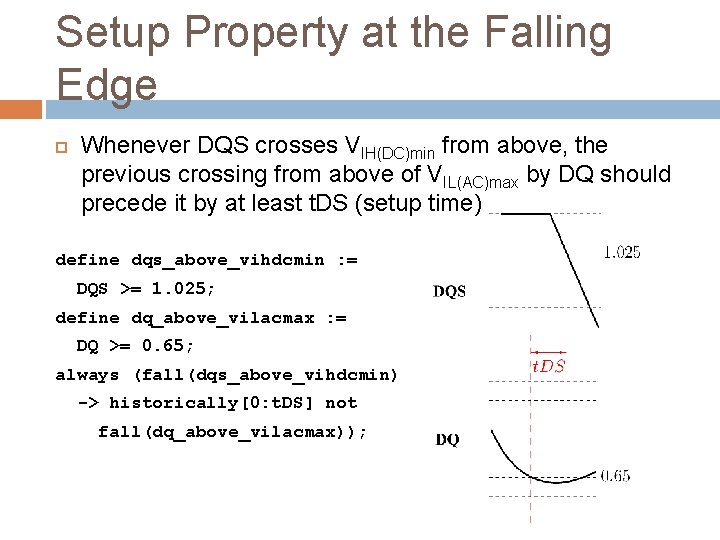
Setup Property at the Falling Edge Whenever DQS crosses VIH(DC)min from above, the previous crossing from above of VIL(AC)max by DQ should precede it by at least t. DS (setup time) define dqs_above_vihdcmin : = DQS >= 1. 025; define dq_above_vilacmax : = DQ >= 0. 65; always (fall(dqs_above_vihdcmin) -> historically[0: t. DS] not fall(dq_above_vilacmax));
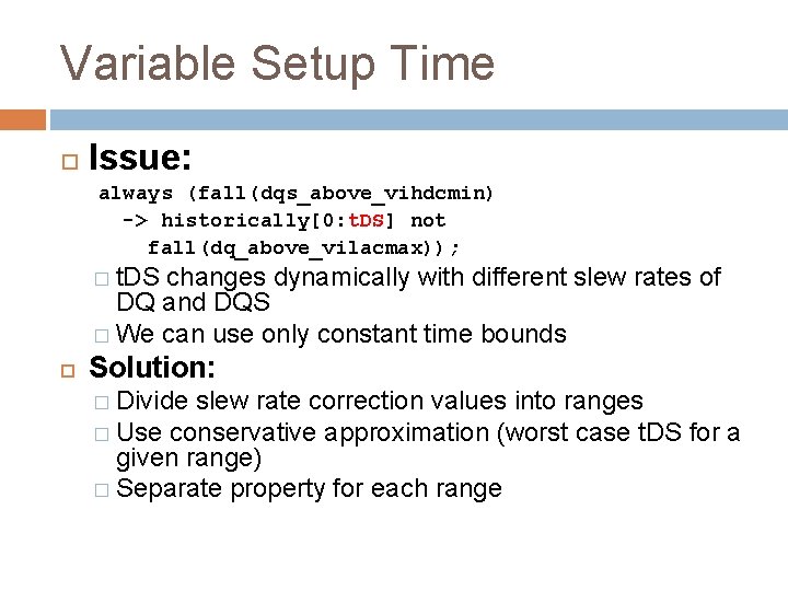
Variable Setup Time Issue: always (fall(dqs_above_vihdcmin) -> historically[0: t. DS] not fall(dq_above_vilacmax)); � t. DS changes dynamically with different slew rates of DQ and DQS � We can use only constant time bounds Solution: � Divide slew rate correction values into ranges � Use conservative approximation (worst case t. DS for a given range) � Separate property for each range
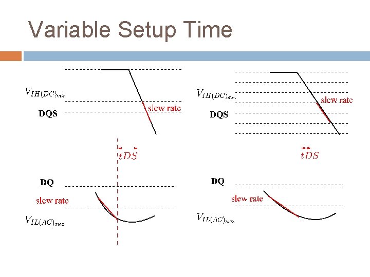
Variable Setup Time
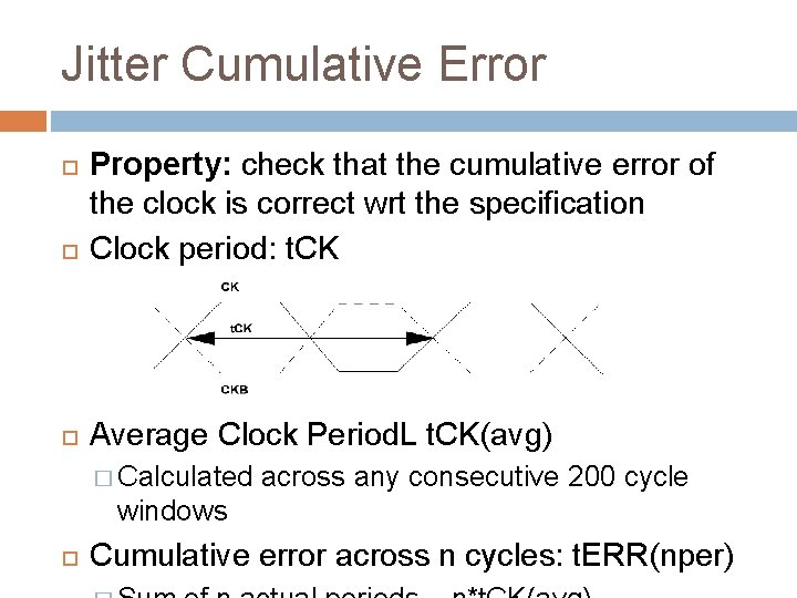
Jitter Cumulative Error Property: check that the cumulative error of the clock is correct wrt the specification Clock period: t. CK Average Clock Period. L t. CK(avg) � Calculated across any consecutive 200 cycle windows Cumulative error across n cycles: t. ERR(nper)
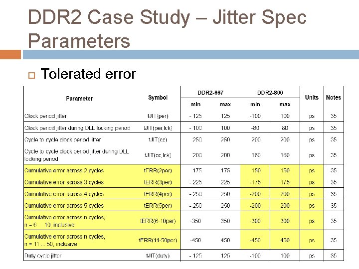
DDR 2 Case Study – Jitter Spec Parameters Tolerated error
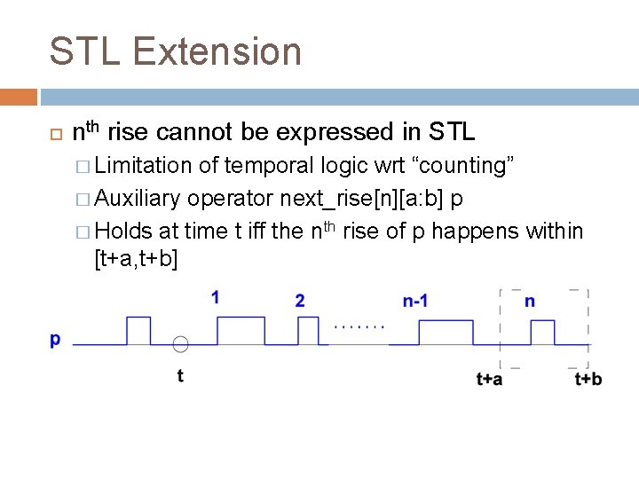
STL Extension nth rise cannot be expressed in STL � Limitation of temporal logic wrt “counting” � Auxiliary operator next_rise[n][a: b] p � Holds at time t iff the nth rise of p happens within [t+a, t+b]
STL Limitation Issue: � t. CK(avg) varies in time, hence time bounds are not fixed Solution: � Manual extraction of the min/max t. CK(avg) from the simulation � Properties expressed wrt the values (conservative) t. CK(avg)min = 1876 ps t. CK(avg)max = 1877 ps
Cumulative Error over 3 Clock Periods Example: t. ERR(3 per) � -175 ps <= t. ERR(3 per) <= 175 ps � For any given clock rise, the 3 rd consecutive clock rise has to happen within [t. CK(avg)-175, t. CK(avg)+175] [t. CK(avg)max-175: t. CK(avg)min+175] [5456: 5803] � Use next_rise[n][a: b] to express this property
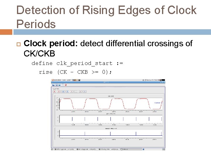
Detection of Rising Edges of Clock Periods Clock period: detect differential crossings of CK/CKB define clk_period_start : = rise (CK – CKB >= 0);
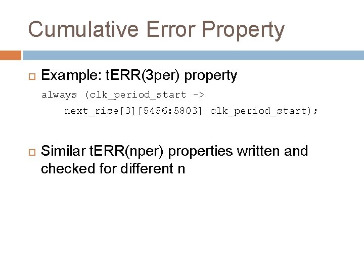
Cumulative Error Property Example: t. ERR(3 per) property always (clk_period_start -> next_rise[3][5456: 5803] clk_period_start); Similar t. ERR(nper) properties written and checked for different n
Summary The framework centered around STL presents a good basis for property-based analog and mixed-signal monitoring But… There are limitations that need to be taken into account!!!
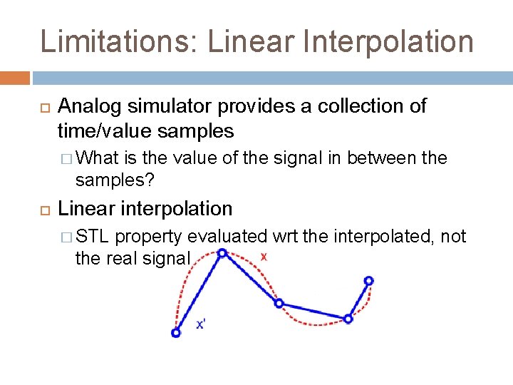
Limitations: Linear Interpolation Analog simulator provides a collection of time/value samples � What is the value of the signal in between the samples? Linear interpolation � STL property evaluated wrt the interpolated, not the real signal
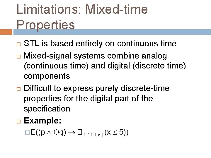
Limitations: Mixed-time Properties STL is based entirely on continuous time Mixed-signal systems combine analog (continuous time) and digital (discrete time) components Difficult to express purely discrete-time properties for the digital part of the specification Example: � �((p q) �[0: 200 ns] (x 5))
Limitations: Regular Expressions SVA and PSL heavily rely on regular expressions (sequence operators) DDR 2 jitter property exposed further the need for regular expression operators
Limitations: Future, Past and Events STL combines future and past operators Expressing events in real-time requires both future and past operators Past operators are difficult to use for online monitoring � This is especially true in the analog setting � The simulator cannot backtrack once it has computed a new sample
Limitations: Expressiveness DDR 2 case study exposed limited expressiveness of STL � Slew rates, averages, variable times… SVA-like local variables?

How to Overcome the Limitations? Accellera ASVA committee � Analog and mixed-signal extension of SVA that addresses most of the above limitations � Provide an industrial-strength framework for property based AMS monitoring
PROPERTY-BASED MONITORING OF AMS SYSTEMS: INDUSTRIAL PERSPECTIVE
Expectations Standardized AMS assertion language � Must be consistently supported across vendors � Must be well integrated with existing languages (Verilog-AMS and System. Verilog) � Build on idioms and styles of existing digital assertions Efficient, accurate online and offline monitoring � So. C-level simulation performance is still important � Poorly performing assertions won’t get used � Offline mode is important for assertion development Assertions can be edited and rechecked without waiting for long AMS simulations to finish
Expected Use Models System-level functional verification � User: Verification engineer � Circuit type: System. Verilog/Verilog AMS/SPICE � Level: System/Chip Model functional verification � User: AMS Verification engineer � Circuit type: Verilog AMS � Level: Block
Expected Use Models Model vs. implementation checking � User: Analog designer or AMS verification engineer � Circuit type: Verilog AMS/SPICE � Level: Block
AMS Assertions Today AMS assertions are approximated using Verilog-AMS monitors and digital SVAs: � Digital signals created by Verilog-AMS monitors are bound into SVA modules � SVAs are clocked by carefully timed signals
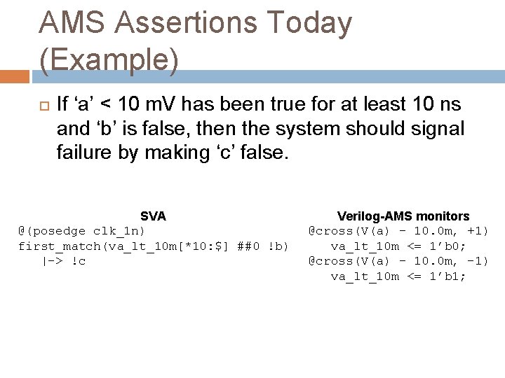
AMS Assertions Today (Example) If ‘a’ < 10 m. V has been true for at least 10 ns and ‘b’ is false, then the system should signal failure by making ‘c’ false. SVA @(posedge clk_1 n) first_match(va_lt_10 m[*10: $] ##0 !b) |-> !c Verilog-AMS monitors @cross(V(a) - 10. 0 m, +1) va_lt_10 m <= 1’b 0; @cross(V(a) – 10. 0 m, -1) va_lt_10 m <= 1’b 1;
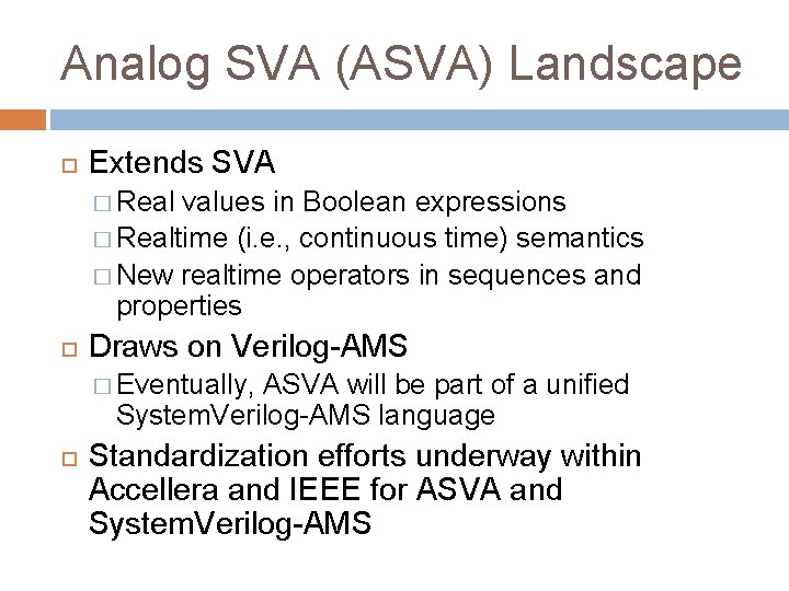
Analog SVA (ASVA) Landscape Extends SVA � Real values in Boolean expressions � Realtime (i. e. , continuous time) semantics � New realtime operators in sequences and properties Draws on Verilog-AMS � Eventually, ASVA will be part of a unified System. Verilog-AMS language Standardization efforts underway within Accellera and IEEE for ASVA and System. Verilog-AMS
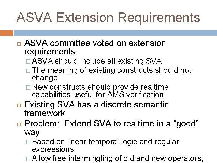
ASVA Extension Requirements ASVA committee voted on extension requirements � ASVA should include all existing SVA � The meaning of existing constructs should not change � New constructs should provide realtime capabilities useful for AMS verification Existing SVA has a discrete semantic framework Problem: Extend SVA to realtime in a “good” way � Based on linear temporal logic and regular expressions � Allow free intermingling of old and new operators,
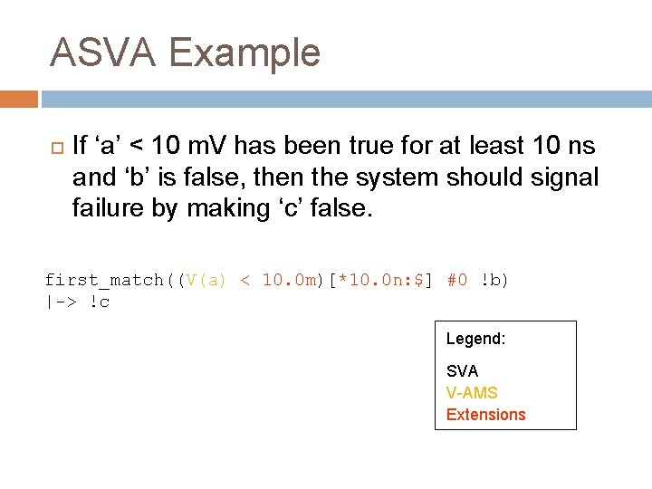
ASVA Example If ‘a’ < 10 m. V has been true for at least 10 ns and ‘b’ is false, then the system should signal failure by making ‘c’ false. first_match((V(a) < 10. 0 m)[*10. 0 n: $] #0 !b) |-> !c Legend: SVA V-AMS Extensions
Existing SVA Landscape SVA consists of several layers � Boolean HDL expressions, but reals are not allowed All booleans are clocked � Sequence Booleans are combined with regular expression operators to define temporal patterns Concatenations (##0, ##n), repetitions ([*n], [*1: $]), connectives (and, or, intersect) � Property Sequences are combined to define temporal logic properties Implications (|->, |=>, if-else), logical connectives (and, or, not), linear temporal logic operators (always, eventually, until)
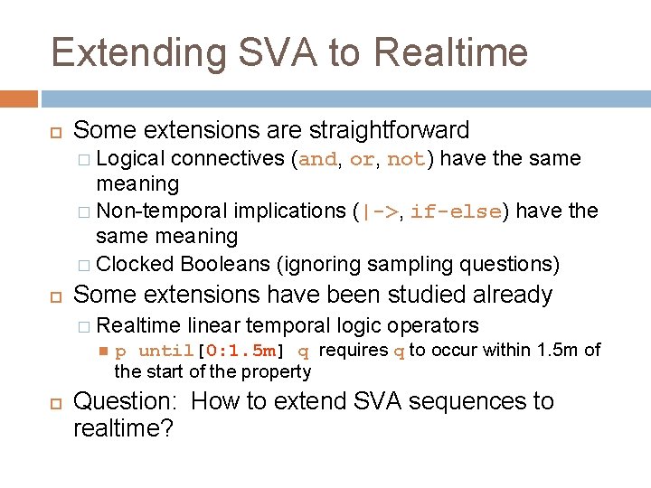
Extending SVA to Realtime Some extensions are straightforward � Logical connectives (and, or, not) have the same meaning � Non-temporal implications (|->, if-else) have the same meaning � Clocked Booleans (ignoring sampling questions) Some extensions have been studied already � Realtime linear temporal logic operators p until[0: 1. 5 m] q requires q to occur within 1. 5 m of the start of the property Question: How to extend SVA sequences to realtime?
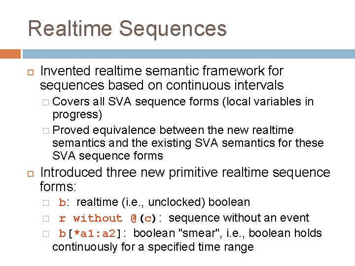
Realtime Sequences Invented realtime semantic framework for sequences based on continuous intervals � Covers all SVA sequence forms (local variables in progress) � Proved equivalence between the new realtime semantics and the existing SVA semantics for these SVA sequence forms Introduced three new primitive realtime sequence forms: b: realtime (i. e. , unclocked) boolean � r without @(c): sequence without an event � b[*a 1: a 2]: boolean "smear", i. e. , boolean holds continuously for a specified time range �
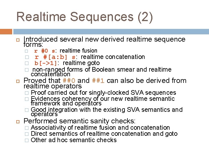
Realtime Sequences (2) Introduced several new derived realtime sequence forms: � � r #0 s: realtime fusion r #[a: b] s: realtime concatenation b[->1]: realtime goto non-ranged forms of Boolean smear and realtime concatenation Proved that ##0 and ##1 can also be derived from realtime operators Proof carried out for singly-clocked SVA sequences Evidences coherency of our new realtime semantic framework and operators � Good integration with the existing SVA semantics and operators � � Performed semantic sanity checks: � � � Associativity of realtime fusion and concatenation Direct semantics of realtime concatenation and goto Other ad hoc semantic checks
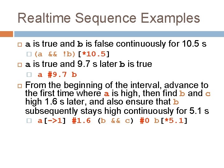
Realtime Sequence Examples a is true and b is false continuously for 10. 5 s � (a a is true and 9. 7 s later b is true � && !b)[*10. 5] a #9. 7 b From the beginning of the interval, advance to the first time where a is high, then find b and c high 1. 6 s later, and also ensure that b subsequently stays high continuously for 5. 1 s � a[->1] #1. 6 (b && c) #0 b[*5. 1]
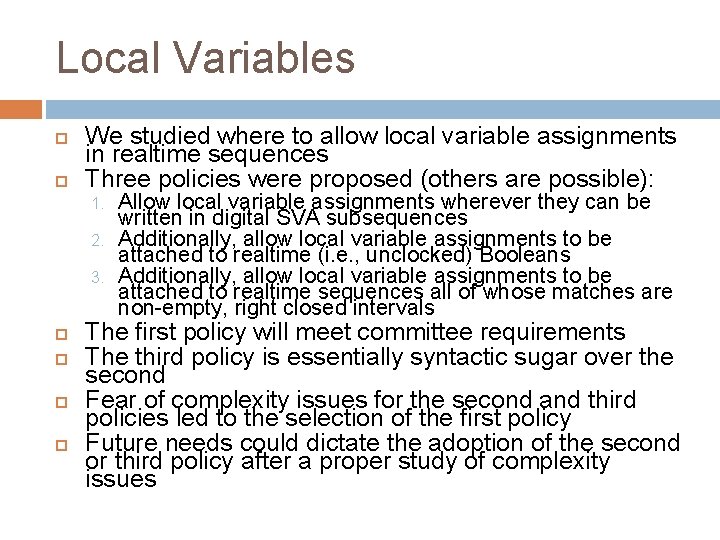
Local Variables We studied where to allow local variable assignments in realtime sequences Three policies were proposed (others are possible): 1. 2. 3. Allow local variable assignments wherever they can be written in digital SVA subsequences Additionally, allow local variable assignments to be attached to realtime (i. e. , unclocked) Booleans Additionally, allow local variable assignments to be attached to realtime sequences all of whose matches are non-empty, right closed intervals The first policy will meet committee requirements The third policy is essentially syntactic sugar over the second Fear of complexity issues for the second and third policies led to the selection of the first policy Future needs could dictate the adoption of the second or third policy after a proper study of complexity issues
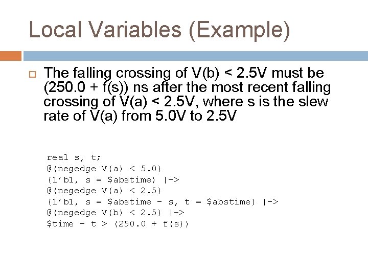
Local Variables (Example) The falling crossing of V(b) < 2. 5 V must be (250. 0 + f(s)) ns after the most recent falling crossing of V(a) < 2. 5 V, where s is the slew rate of V(a) from 5. 0 V to 2. 5 V real s, t; @(negedge V(a) < 5. 0) (1’b 1, s = $abstime) |-> @(negedge V(a) < 2. 5) (1’b 1, s = $abstime – s, t = $abstime) |-> @(negedge V(b) < 2. 5) |-> $time – t > (250. 0 + f(s))
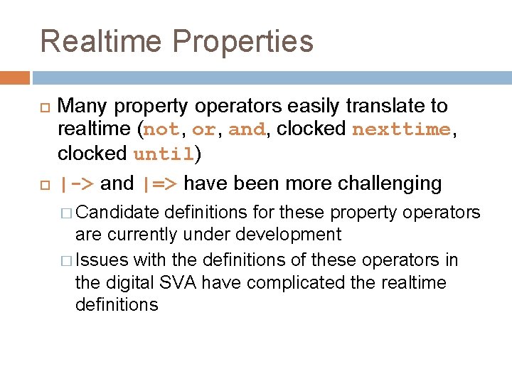
Realtime Properties Many property operators easily translate to realtime (not, or, and, clocked nexttime, clocked until) |-> and |=> have been more challenging � Candidate definitions for these property operators are currently under development � Issues with the definitions of these operators in the digital SVA have complicated the realtime definitions
Mixed-time Specification Language Many truly mixed-signal properties are more easily specified with a mixed-time language � Clocked trigger implies start realtime measurement (e. g. , settling time, slew rate) A free intermingling of clocked and realtime sequences and properties is a key feature of ASVA
Accurate Simulations for Assertions Accuracy of analog events is critical for correct assertions. Assertion writers require the ability to influence the analog simulator time steps according to the needs of the property Implicit inference of critical solve points based on assertion structure is preferred � Further study is needed to understand the feasibility of critical solve point inference and performance impact
Embedding ASVA within SV and VAMS ASVA is ideally suited to a merged System. Verilog/Verilog-AMS language Without a merged language it is difficult for: � ASVA within SV to access continuous quantities & events (e. g. , V(a), @(cross())) � ASVA with VAMS to access complex testbench data types (e. g. struct) Compromises will be made

CONCLUSIONS AND FURTHER PERSPECTIVES
Other Extensions Robust satisfaction of STL � Today 17 h presentation [Donze. Maler 10] Parametric MITL � Extract timing bounds from a set of simulations always (p -> eventually[? ] q) � [Di. Giampaolo. La. Torre. Napoli 10]
Conclusion Exporting property-based monitoring to the AMS context � Comprehensive prototype tool applied to real industrial case studies Industrial interest in the methodology � Freescale, Mentor Graphics, Rambus, STM… Accellera ASVA committee � Towards a standard property specification language for AMS applications � Work in progress
- Slides: 87