Projects Overview Air Bag Inflator Bonfire Test Air

Projects Overview • • Air Bag Inflator Bonfire Test Air Bag Inflator Weld Study Compact Heat Exchanger for Aircraft Fuel Cooled Oil Cooler Fire Test Halogen Light Fixture Solar Water Heater Radiative Heating of Aircraft Strut by Hot Exhaust Pipe Electronics Board Pinckney Engineering International pinckneyconsulting@yahoo. com (480) 558 -4986
 558 -4986")
Air Bag Inflator Bonfire Test Pinckney Consulting pinckneyconsulting@yahoo. com (480) 558 -4986

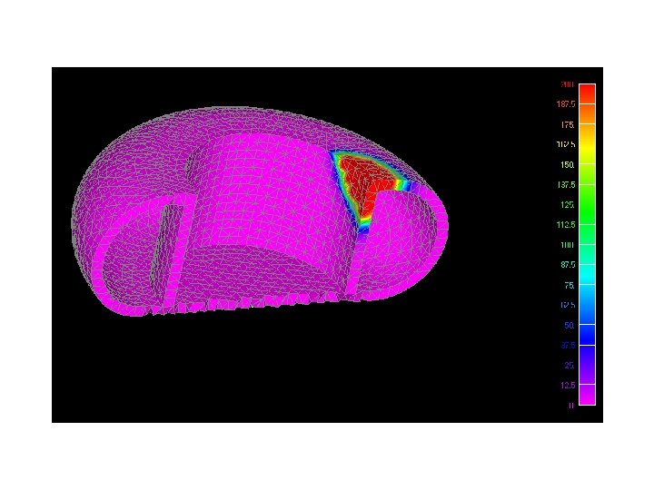
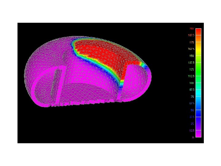
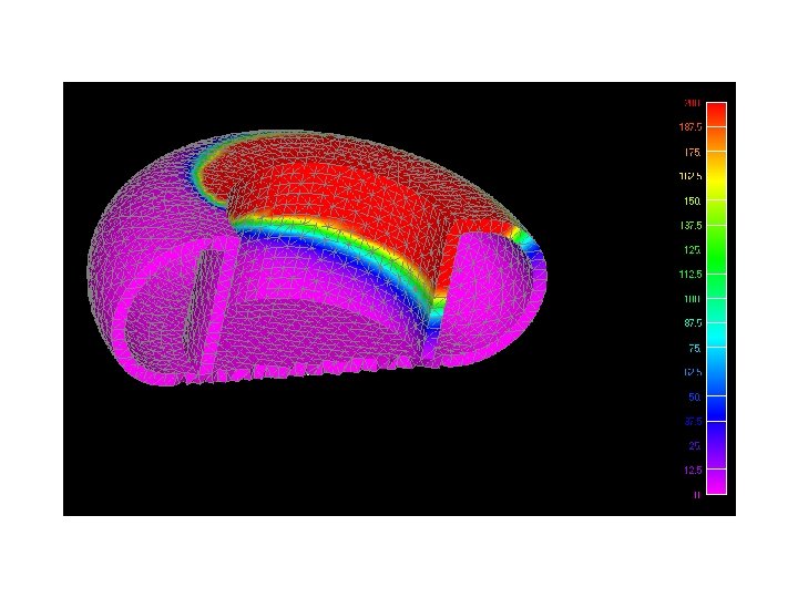
400 OC Boundary conditions on bottom surfaces of pressurized inflator. Gas pressure increases until burst disk ruptures. • Air is modeled as a single node • Contact Segments used to connect air node and inside walls of inflator • Gas pressure is calculated as heat is added until burst disk ruptures • Convection is increased during venting • Sonic and subsonic flow regimes are modeled

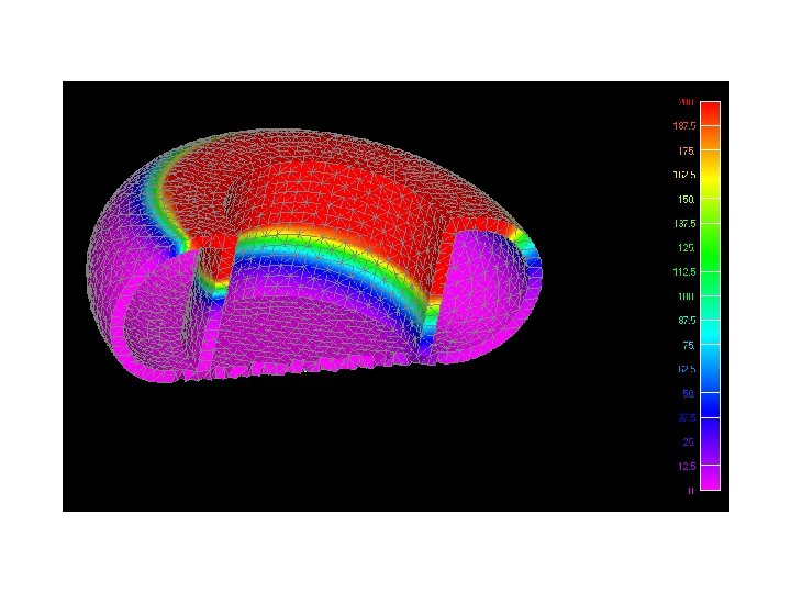
Graph capturing rupture of burst disk and temperatures at locations within the pressure vessel at time of bursting.
 558 -4986")
Air Bag Inflator Weld Process Study John Pinckney pinckneyconsulting@yahoo. com (480) 558 -4986

Find Temperatures in Areas that Contain the Propellant During the Welding Process Cap Welded to Bottle Propellant Location

Apply Weld Heat to Nodes on Edge of Cap

Turn On Conductors Between Cap and Bottle as Weld Progresses


Transient Thermal Analysis of Compact Cross Flow Heat Exchanger for Aviation Application • Pulsed hot air operation • Modeled using innovative technique of applying fin equations within SINDA/G for Femap • Results used for performance and thermal stress analysis By John Pinckney pinckneyconsulting@yahoo. com (480) 558 -4986

Super Fin sections modeled as three nodes with two conductors and two heat terms. See: Fundamentals of Heat Exchanger Design. Ramesh K. Shah, Dusan P. Sekulic. John Wiley & Sons, Hobeken, New Jersey. 2003 is difference in temperatures between air stream and fin location.

The fin equations are necessary because large errors will result in the convective heat transfer calculations otherwise. It is impractical to mesh fins fine enough to accurately capture the fin temperature profile. A fin temperature profile.
 from air streams to parting plates were constructed by")
Convection conductors (shown in red) from air streams to parting plates were constructed by using the Contact Segments Algorithm.

Initial temperatures are steady state with steady flow.

Letter of Appreciation for Phase 1
 558 -4986")
Fuel Cooled Oil Cooler Fire Test John Pinckney pinckneyconsulting@yahoo. com (480) 558 -4986

• Goals • Find fluid and wall temperatures after 15 minutes under conditions of onboard fire. • Wall temperature to be < 380 o. C. • Recommend any design changes. • Boundary Conditions: • Heat flux of 120, 000 watts/m 2 is the assumed fire conditions. • Fuel and oil inlet temperatures are 20 o. C and 95 respectively o. C.

Heat Exchanger Efficiency used in SINDA/G Model to Calculate Outlet Temperatures • Convection coefficient is calculated using correlation. • NTU method is used for calculating heat exchanger efficiency. • Efficiency used to compute fluid outlet temperatures. Efficiency for cross-flow heat exchanger.

Results The wall temperatures greatly exceeded the adverse service specifications. Consider convection enhancement of adding pin fins.

Use correlation to compute convection coefficient from the pins. Compute pin efficiency and overall efficiency.

300 pin fins to the surface of the cover plates would be sufficient to meet adverse service temperature specifications.
 558 -4986")
Thermal Analysis of Recessed Halogen Light Fixture John Pinckney pinckneyconsulting@yahoo. com (480) 558 -4986

Halogen Light Fixture Model View factors computed using Nevada. Mc. Adams relations update convection conductors.
 Bulb (o. C) Lens (o. C) Schematic")
Temperature Results with Convection Reflector (o. C) Bulb (o. C) Lens (o. C) Schematic 192 989 123 Nevada/Femap 193 991 115

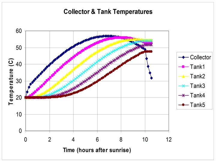
Solar Water Heater Study • Day in the life of a solar water heater in Phoenix Arizona on Dec 21 st. • One-way conductors are used for water flow. • Radiation to the sky and convection to ambient air is accounted for. Pinckney Engineering International pinckneyconsulting@yahoo. com (480) 558 -4986

Convection Correlation Used to Compute Convection from Collector to Air. SINDA/G User’s Guide, Network Analysis Copyright © 2005

Radiative Heating of Aircraft Strut by Hot Exhaust Pipe Pinckney Engineering International pinckneyconsulting@yahoo. com (480) 558 -4986

Native CAD Geometry is Overly Complex The CAD geometry is too complex to model for current Monte Carlo radiation solvers. A fully meshed strut contains almost 48, 000 elements. Ray tracing from all the element faces would take days. The geometry must be simplified before exporting to a radiation solver.

A preliminary model can be constructed in Nevada. The model contains all the essential features. Here the pipe is modeled as a straight cylinder. The radiation conductors between surfaces are computed by Nevada and thermal results obtained by SINDA/G.

New geometry in constructed in Femap using the basic dimensions of the strut.

The simplified geometry was meshed and model analyzed.

The results of the two models compared.

Add a radiation shield to the pipe.

The effect of the radiation shield on temperatures.
 558 -4986")
Thermal Analysis of Electronics Board Pinckney Engineering International pinckneyconsulting@yahoo. com (480) 558 -4986

Surfaces for component footprints are placed on the board. Powers are assigned to components on the board. Top and bottom of board set to card guide temperatures of chassis, 71. 2 OC and 74. 7 OC, respectively.

Model is analyzed and temperatures plotted.

A slightly different board layout is considered. Components are easily moved on the board since they are represented by independent surfaces.

The new layout is analyzed.

A Component Report is generated. Part # Location Power Theta. CB Theta. JC Tboard Tjunction Tj. Max SMargin LM 1336 C 1 0. 65 9. 6 20 88. 7 107. 94 125 -17. 06 LM 1336 C 2 0. 65 9. 6 20 87. 9 107. 14 125 -17. 86 LM 1336 C 3 0. 65 9. 6 20 90. 7 109. 94 125 -15. 06 LM 1398 C 4 0. 56 11. 2 30 84. 7 107. 772 125 -17. 228 LMC 140 A C 6 0. 22 11. 2 30 87. 2 96. 264 125 -28. 736 LMC 140 A C 8 0. 22 11. 2 30 92. 1 101. 164 125 -23. 836 LMC 140 A C 10 0. 22 11. 2 30 90. 6 99. 664 125 -25. 336 The average of absolute value of SMargin is increased by 40% with new board layout.
- Slides: 45