Projector with Radiometric Screen Compensation Shree K Nayar


 I camera irradiance projector brightness D Display Device M")
 I camera irradiance projector brightness D Display")
 camera irradiance arbitrary image only change in red")


 Texture of")
 image (I) ~ Compensation image ( I")


- Slides: 18
Projector with Radiometric Screen Compensation Shree K. Nayar, Harish Peri Michael Grossberg, Peter Belhumeur Computer Science Columbia University Procams Workshop ICCV 2003, Nice, France Support: National Science Foundation
Projecting on Any Surface ?
Projector-Camera System Textured Screen Camera Computer Projector
Geometric Calibration Projector Input Camera Output Maximum Error: 0. 6 pixels, RMS Error: 0. 18 pixels
Projector-Camera Pipeline: Radiometry I xi D Display Device M xm Screen xd P Projector E B Capture Device xb C L xs Camera What Display Image (I) will produce a Desired Captured Image (M) ?
Radiometric Model (for each pixel) I camera irradiance projector brightness D Display Device M color mixing matrix projector channel screen P Screen Projector E B Capture Device projector reponse C Camera display reponse camera channel camera reponse capture reponse L
Finding the Model Parameters (at each pixel) I camera irradiance projector brightness D Display Device M color mixing matrix (known) camera irradiance E C L Camera composite response projector brightness modified color mixing matrix Screen Projector B Capture Device P projector color display image color
Finding the Color Mixing Matrix (known) camera irradiance arbitrary image only change in red only change in green only change in blue projector brightness modified color mixing matrix
Color Mixing: V Matrices
Radiometric Calibration: Color composite response compensated display image desired projector output Projector Input Camera Output
Color Experiment Uncompensation outputs (flat gray inputs: 100, 150, 200 gray levels) Texture of Screen Projected Brightness (R, G, B) 50, 50 Max. Error RMS Error (R, G, B) Without With Comp. 25, 26 2, 3, 7 24. 1, 24. 2, 24. 5 0. 6, 0. 8, 1. 7 Compensation images (flat gray inputs: 100, 150, 200 gray levels) 100, 100 66, 70, 71 6, 8, 14 58. 9, 57. 2, 64. 9 1. 6, 1. 9, 5. 4 150, 150 75, 98, 95 19, 15, 21 49. 0, 44. 5, 69. 1 4. 8, 3. 1, 5. 8 200, 200 50, 99, 90 39, 25 27. 7, 47. 5, 42. 7 12. 7, 4. 0, 10. 7 Compensation Accuracy Compensated outputs (flat gray inputs: 100, 150, 200 gray levels)
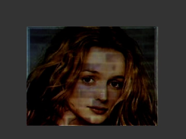
Face Image on Checkerboard Screen Original (desired) image (I) ~ Compensation image ( I ) Uncompensated output (M) ~ Compensated output (M)
Face Video on Brick Texture Normal Projector With Compensation
Scene Video on Brick Texture Normal Projector With Compensation
Face Video on Butterfly Poster Normal Projector With Compensation
Summary • Radiometric Model for Projector-Camera System • Off-Line Method for Radiometric Calibration • On-Line Algorithm for Screen Compensation • Refinement using Continuous Feedback