Projection TongYee Lee 1 Readings Computer Graphics Using


v. s. Orthographic (正投影) projection 3")


 d=(0, 0, 1, 0) Note that projection vector d")

 -Z Translate")


")


 In the eye space coordinate (right-hand system) In the image (screen) space")


 X, Y, Z axis")


 goes to the face w =")

 and (0, 0, 1) So,")
 the above P has transformed any point to")


 when r = -")
 We use")
. Otherwise,")

 = (0, 0,")
 rv=lv+(w-1), tv=bv+(h-1) Zs will")


 glut. Init. Windowposition(x, y) (0, 0) (x, y) w h")
 w (xmax, ymax) (x 1, y 1) (0, 0) h Window coordinate")


; glu. Perspective(60. 0, 1. 3,")
- Slides: 69
Projection Tong-Yee Lee 1
Readings Computer Graphics Using Open. GL by F. S Hill, J. R. Chapter 7 2
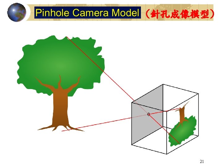
Perspective(透視投影)v. s. Orthographic (正投影) projection 3
Multi-view Orthographic 4
5
Oblique parallel projection 6
7
8
9
10
Zs is lost , so it can not be used for Visible Surface Removal!!!11
d (dx, dy, dz, 0) d=(0, 0, 1, 0) Note that projection vector d (dx, dy, dz, 0) is specified from -Z toward Z in the eye space coordinate 12
What Open. GL wants is: Regardless of parallel projection or perspective projection!! ! After projection, the image space (after division) become ……. (1) Left hand system (2) -1<=xs, ys, zs <=1 13
-Z Parallel Projection in Open. GL glortho(l, r, b, t, n, f) -Z Translate and Scale l (x’, 0) r +X d=(0, 0, 1, 0) -1 +1 +X 14
Parallel Projection Matrix in Open. GL Image space in right hand system negate Z Image space in left hand system (Open. GL) 15
This row will not affect the projection!!! Only affect the Zs value! And substitute the following to solve A and B 16
Final Parallel Projection Matrix in Open. GL gl. Ortho(l, r, b, t, n, f) In parallel projection, w term also is 1. We do not need division!! Zs is good for Hidden Surface Removal !!! Zs is not lost So, we want this model!! Zs is lost 17
What Open. GL wants is: Regardless of parallel projection or perspective projection!! ! After projection, the image space (after division) become ……. (1) Left hand system (2) -1<=xs, ys, zs <=1 18
Object is distorted in screen space but the projection result is still same!! 19
20
22
23
24
25
26
27
28
OR Remember this!! Zs is lost again!! 29
30
31
(after division) In the eye space coordinate (right-hand system) In the image (screen) space coordinate (left hand system) 32
Object is distorted in screen space but the projection result is still same!! 33
- 34
Essentials of Interactive Computer Graphics: Concepts and Implementation K. Sung, P. Shirley, S. Baer 3 D NDC to 2 D Image (Near) Plane Resulting image on the near plane Chapter 14
fovx and fovy are assumed to be equal Note (1) X, Y, Z axis are named u, v, w in the following discussions! 36
Note that the representation of point transform is different from the previous one in the following discussions: For example: Old New 37
38
Good when we choose a canonical screen space volume or clipping volume Clipping Space Coordinate 39
In clipping coordinate space, we perform clipping. We can therefore save division if points are outside the frustum of clipping coordinate space We will teach clipping soon! 40
41
Something Interesting …Clipping What does it imply? Remember if a point is behind eye, we can not see it!!. i. e. , w > 0, means it is behind eye. So, we can check the fourth item (before division). If the fourth item is negative, this point is behind the eye point. 42
We neglect scales at X and Y first and we Will compute them latter 43
the near plane (w = - n ) goes to the face w = -1 of the image space cub , and the face defined by the far plane (w = - f ) goes to the face w = 1 of the image space cube. That’s Note that in image space (0, 0, -n)P = (0, 0, -1) (after division) (0, 0, -f)P = (0, 0, 1) 44
45
We want to map them to (0, 0, -1) and (0, 0, 1) So, 46
We should also note that (1) the above P has transformed any point to image space (left hand system (n=-1, f = 1)). Zs is lost So, as Zs is larger, it means it is far away from camera. (2) Point in image space will not lost its Zs component!! 47
48
But, we want this term to be 1. So, after division, we get : 49
Scale can help ………. Before we apply projection, we scale X, Y …………. . 50
Re-organize our Representation !!!! Clipping space division Eye space fovx and fovy can be different!! Image (screen) space 51
Furthermore ……………… glu. Frustum (l, r, b, t, n, f) when r = - l , b = -t , we will have a symmetric frustrum -X -r -Z eye Z=-n r 52
Final Projection Matrix Used in Open. GL glu. Perspective(angle, aspect, n, f) We use angle and aspect ratio to find l, r, t, b by the following…. . l -Z eye Z=-n r +X 53
Programmer must responsibly specify correct ratio in viewport gl. Viewport(x, y, w, h). Otherwise, the result will be distorted. 54
55
For example: when zc = 0; Eye (Xc, Yc, Zc, 1) = (0, 0, 0, 1) P(Eye): z’c = -2 fn/(f-n), w’c=0; Inside –w’c <=z’c<=w’c So, P(EYE) is outside, so, we avoid division by zero 56
Normalized Device Coordinate To Window Coordinate glviewport(lv, bv, w, h) rv=lv+(w-1), tv=bv+(h-1) Zs will be translated and scaled to be (0, 1) 57
58
59
Mapping from Window Coordinate to Monitor Screen Coordinate Usually done by your window system for you. Screen Coordinate: (0, 0) is at left-top corner and y is increasing downward the screen (0, 0) (xmax, ymax) Monitor Screen Coordinate (0, 0) Window coordinate (xmax, ymax) 60
glut. Init. Windowsize(w, h) glut. Init. Windowposition(x, y) (0, 0) (x, y) w h Monitor Screen window 61
(0, 0) w (xmax, ymax) (x 1, y 1) (0, 0) h Window coordinate (x, y) h (x 2, y 2) Monitor Screen Coordinate w (xmax’, ymax’) 62
63
View Frustum Culling 64
Depth Buffer 65
Z-buffer 66
Z-buffer For trivial setting Zn, Zf value such as Zn = 0, Zf = 10000000. Then, each polygon’s Z-value of above equation is close to 1, so we need more depth resolution (i. e. , more bits per pixel to represent Z-buffer value) of Z-buffer to make difference. Otherwise, the about the value of above equation is almost the same (i. e. , close to 1, so we can not make difference). 67
Z-buffer 68
glu. Perspective(60. 0, 1. 3, 1. 0, 30000. 0); glu. Perspective(60. 0, 1. 3, 10000. 0, 30000. 0); A good advice: first check the bounding box containing your scene and then make your near plane away from your eye and close to far plane as possibly as you could. 69