
Progress on the fast pulsed kicker for the

- Slides: 24
Progress on the fast pulsed kicker for the HEPS Hua Shi, Jinhui Chen, Lei Wang, Na Wang, Lihua Huo, Peng Liu, Yan Li LER 2016, October 26 -28, 2016
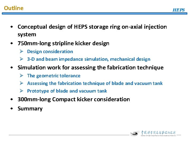
Outline • Conceptual design of HEPS storage ring on-axial injection system • 750 mm-long stripline kicker design Ø Design consideration Ø 3 -D and beam impedance simulation, mechanical design • Simulation work for assessing the fabrication technique Ø The geometric tolerance Ø Assessing the fabrication technique of blade and vacuum tank Ø Prototype of blade and vacuum tank • 300 mm-long Compact kicker consideration • Summary HEPS
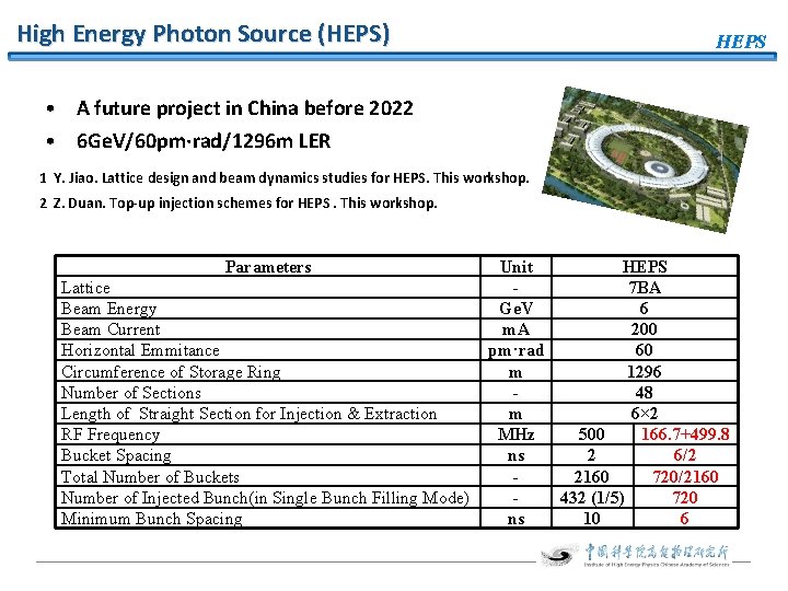
High Energy Photon Source (HEPS) HEPS • A future project in China before 2022 • 6 Ge. V/60 pm·rad/1296 m LER 1 Y. Jiao. Lattice design and beam dynamics studies for HEPS. This workshop. 2 Z. Duan. Top-up injection schemes for HEPS. This workshop. Parameters Lattice Beam Energy Beam Current Horizontal Emmitance Circumference of Storage Ring Number of Sections Length of Straight Section for Injection & Extraction RF Frequency Bucket Spacing Total Number of Buckets Number of Injected Bunch(in Single Bunch Filling Mode) Minimum Bunch Spacing Unit HEPS 7 BA Ge. V 6 m. A 200 pm·rad 60 m 1296 48 m 6× 2 MHz 500 166. 7+499. 8 ns 2 6/2 2160 720/2160 432 (1/5) 720 ns 10 6
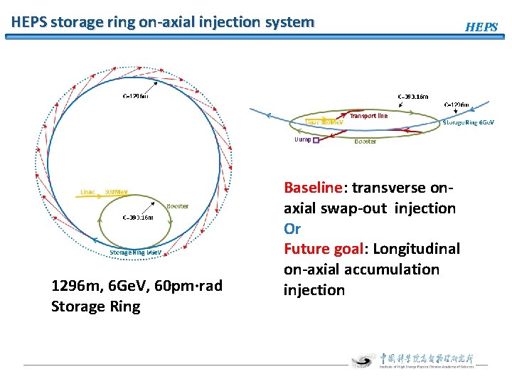
HEPS storage ring on-axial injection system 1296 m, 6 Ge. V, 60 pm·rad Storage Ring Baseline: transverse onaxial swap-out injection Or Future goal: Longitudinal on-axial accumulation injection HEPS
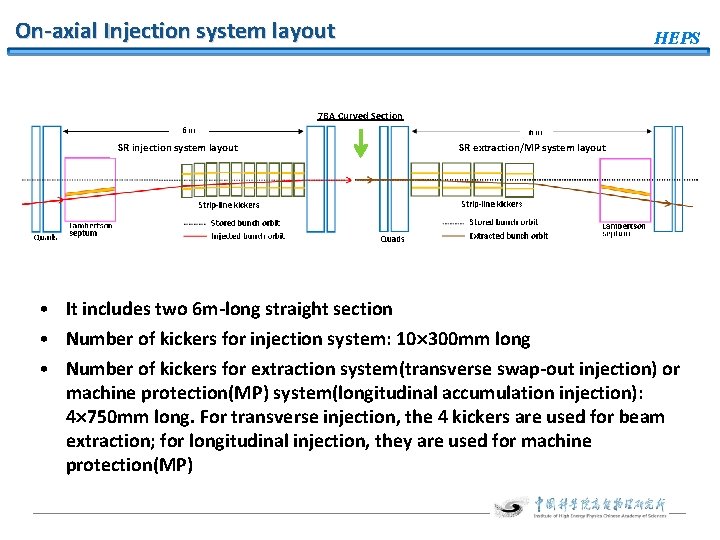
On-axial Injection system layout HEPS 7 BA Curved Section SR injection system layout SR extraction/MP system layout • It includes two 6 m-long straight section • Number of kickers for injection system: 10 300 mm long • Number of kickers for extraction system(transverse swap-out injection) or machine protection(MP) system(longitudinal accumulation injection): 4 750 mm long. For transverse injection, the 4 kickers are used for beam extraction; for longitudinal injection, they are used for machine protection(MP)
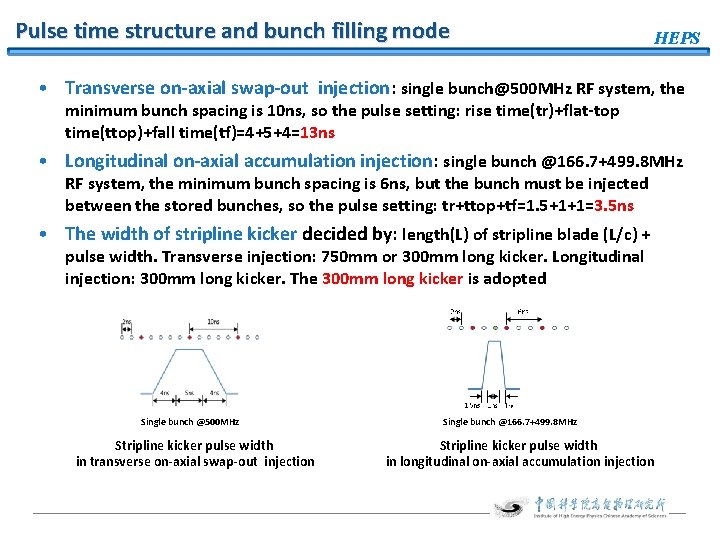
Pulse time structure and bunch filling mode HEPS • Transverse on-axial swap-out injection: single bunch@500 MHz RF system, the minimum bunch spacing is 10 ns, so the pulse setting: rise time(tr)+flat-top time(ttop)+fall time(tf)=4+5+4=13 ns • Longitudinal on-axial accumulation injection: single bunch @166. 7+499. 8 MHz RF system, the minimum bunch spacing is 6 ns, but the bunch must be injected between the stored bunches, so the pulse setting: tr+ttop+tf=1. 5+1+1=3. 5 ns • The width of stripline kicker decided by: length(L) of stripline blade (L/c) + pulse width. Transverse injection: 750 mm or 300 mm long kicker. Longitudinal injection: 300 mm long kicker. The 300 mm long kicker is adopted Single bunch @500 MHz Stripline kicker pulse width in transverse on-axial swap-out injection Single bunch @166. 7+499. 8 MHz Stripline kicker pulse width in longitudinal on-axial accumulation injection
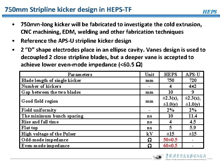
750 mm Stripline kicker design in HEPS-TF HEPS • 750 mm-long kicker will be fabricated to investigate the cold extrusion, CNC machining, EDM, welding and other fabrication techniques • Reference the APS-U stripline kicker design • 2 “D” shape electrodes place in an ellipse cavity. Vanes design is used to decoupled 2 close stripline blades, but a deeper vane is accepted to achieve lower even-mode impedance (<60. 5 ) Parameters Blade length of single kicker Number of kickers Gap between the two blades Unit mm mm Good field region mm Field uniformity The minimum bunch spacing Rise and fall time Flat top High voltage of the Pulser Odd-mode impedance Even-mode impedance ns ns ns k. V HEPS 750 4 10 ± 2. 3(x), ± 1. 0(y) 2% 10 4 5 ± 15 50± 0. 5 60± 0. 5 APS-U 720 4 2 9 ± 2. 3(x), ± 1. 0(y) 2% 11. 4 4. 5 5. 9 ± 15 -
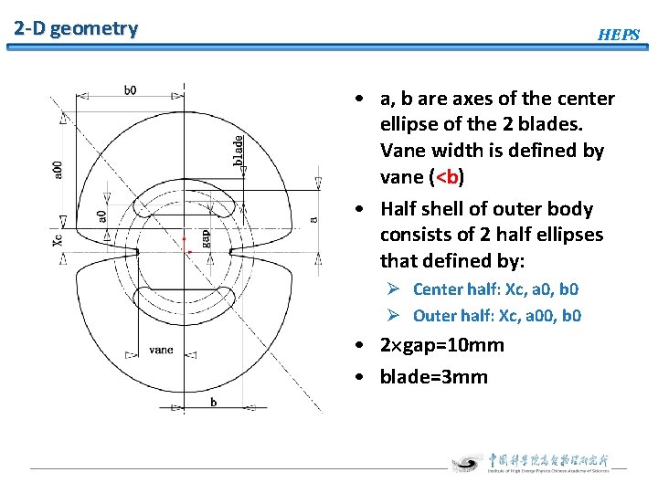
2 -D geometry HEPS • a, b are axes of the center ellipse of the 2 blades. Vane width is defined by vane (<b) • Half shell of outer body consists of 2 half ellipses that defined by: Ø Center half: Xc, a 0, b 0 Ø Outer half: Xc, a 00, b 0 • 2 gap=10 mm • blade=3 mm
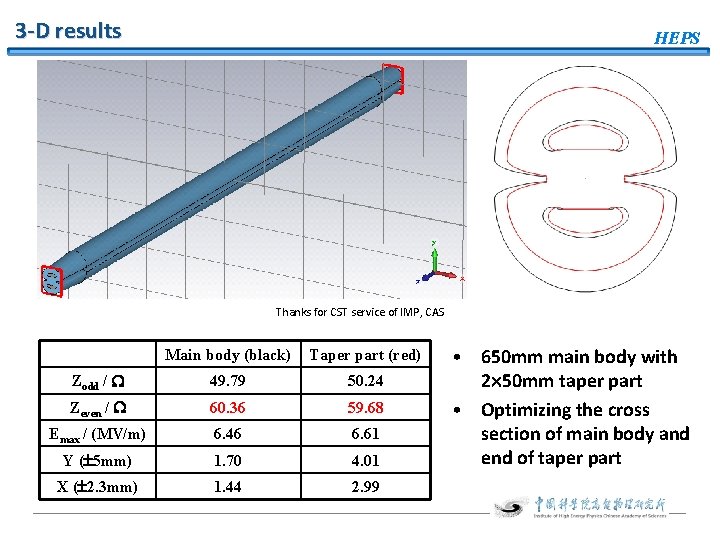
3 -D results HEPS Thanks for CST service of IMP, CAS Main body (black) Taper part (red) Zodd / 49. 79 50. 24 Zeven / 60. 36 59. 68 Emax / (MV/m) 6. 46 6. 61 Y ( 5 mm) 1. 70 4. 01 X ( 2. 3 mm) 1. 44 2. 99 • 650 mm main body with 2 50 mm taper part • Optimizing the cross section of main body and end of taper part
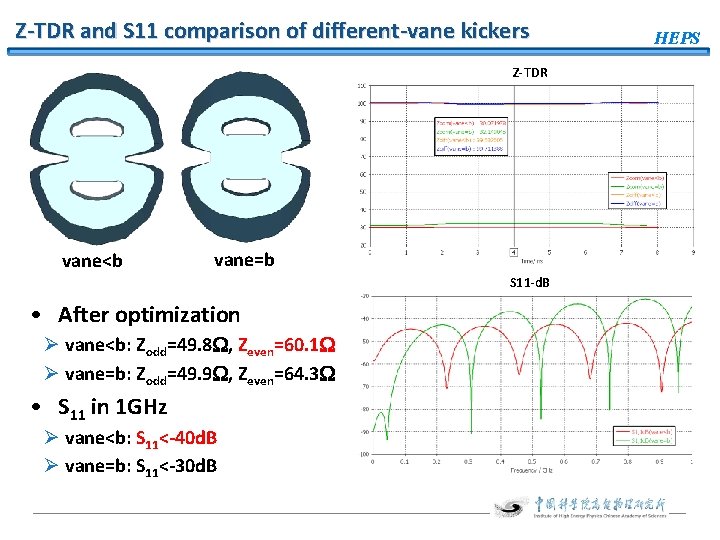
Z-TDR and S 11 comparison of different-vane kickers Z-TDR vane<b vane=b S 11 -d. B • After optimization Ø vane<b: Zodd=49. 8 , Zeven=60. 1 Ø vane=b: Zodd=49. 9 , Zeven=64. 3 • S 11 in 1 GHz Ø vane<b: S 11<-40 d. B Ø vane=b: S 11<-30 d. B HEPS
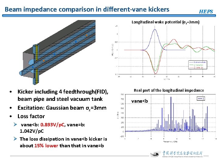
Beam impedance comparison in different-vane kickers HEPS Longitudinal wake potential (σz=3 mm) • Kicker including 4 feedthrough(FID), beam pipe and steel vacuum tank • Excitation: Gaussian beam σz=3 mm • Loss factor Ø vane<b: 0. 893 V/p. C, vane=b: 1. 042 V/p. C Ø The loss dissipation in vane<b kicker is about 15% lower than that in vane=b Real part of the longitudinal impedance vane<b
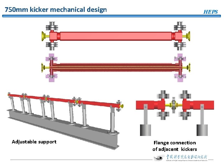
750 mm kicker mechanical design Adjustable support HEPS Flange connection of adjacent kickers
Simulation work for assessing the fabrication technique • The geometric tolerance • Comparison of the fabrication technique of blades • Assess the uniform-section stainless steel blade with Cold Extrusion technique Ø Simulating the kicker made of different material Ø Simulating the kicker without taper • Determine the fabrication technique of vacuum tank Ø Comparison of different welding method of the vacuum tank Ø WEC and welding of vacuum tank • Assess the effect of copper-blade deflection to kicker RF performance Ø Simulating kicker with deflection of different material HEPS
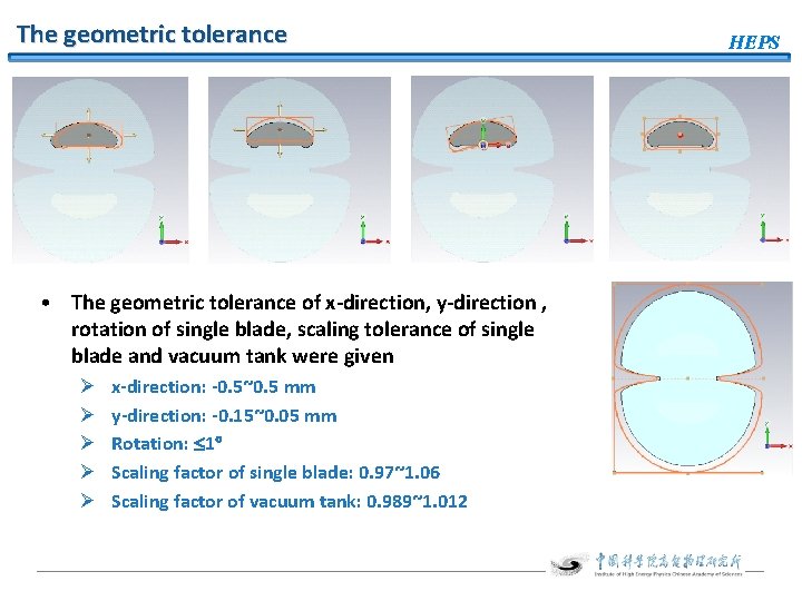
The geometric tolerance • The geometric tolerance of x-direction, y-direction , rotation of single blade, scaling tolerance of single blade and vacuum tank were given Ø Ø Ø x-direction: -0. 5~0. 5 mm y-direction: -0. 15~0. 05 mm Rotation: 1 Scaling factor of single blade: 0. 97~1. 06 Scaling factor of vacuum tank: 0. 989~1. 012 HEPS
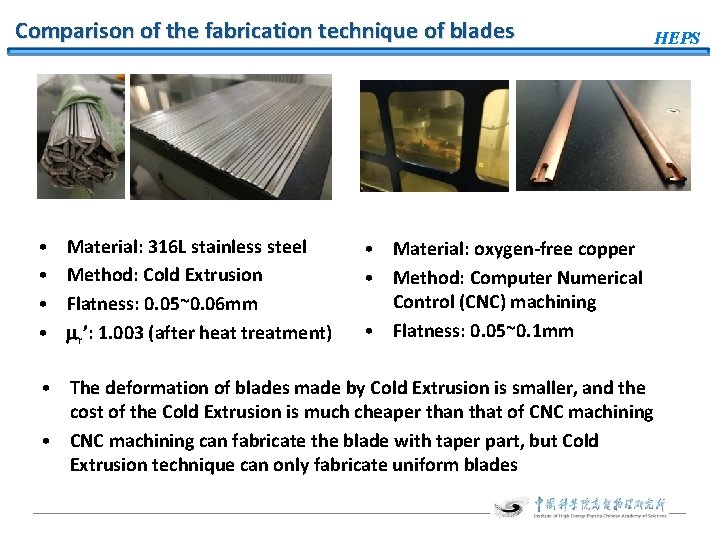
Comparison of the fabrication technique of blades • • Material: 316 L stainless steel Method: Cold Extrusion Flatness: 0. 05~0. 06 mm r’: 1. 003 (after heat treatment) HEPS • Material: oxygen-free copper • Method: Computer Numerical Control (CNC) machining • Flatness: 0. 05~0. 1 mm • The deformation of blades made by Cold Extrusion is smaller, and the cost of the Cold Extrusion is much cheaper than that of CNC machining • CNC machining can fabricate the blade with taper part, but Cold Extrusion technique can only fabricate uniform blades
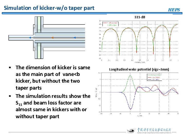
Simulation of kicker-w/o taper part HEPS S 11 -d. B • The dimension of kicker is same as the main part of vane<b kicker, but without the two taper parts • The simulation results show the S 11 and beam loss factor are almost same in kickers with or without taper part Longitudinal wake potential (sigz=3 mm)
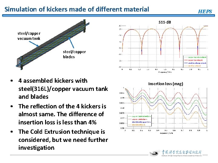
Simulation of kickers made of different material HEPS S 11 -d. B steel/copper vacuum tank steel/copper blades • 4 assembled kickers with steel(316 L)/copper vacuum tank and blades • The reflection of the 4 kickers is almost same. The difference of insertion loss is less than 4% • The Cold Extrusion technique is considered, but we need further investigation Insertion loss (mag)
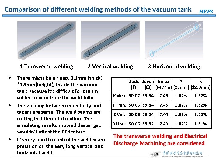
Comparison of different welding methods of the vacuum tank 1 Transverse welding • • • 2 Vertical welding There might be air gap, 0. 1 mm (thick) *0. 5 mm(height), inside the vacuum tank because it’s difficult for the tin solder to penetrate the weld fully The welding between main body and tapers are same. The weld seams are cutting in different direction. The simulating results showed the air gap wouldn’t affect the RF feature It’s very hard to control the weld seam precision of the very long vertical and horizontal weld HEPS 3 Horizontal welding Zodd Zeven Emax Y X ( ) (MV/m) (± 5 mm) (± 2. 3 mm) Kicker 50. 07 59. 54 7. 45 1. 82% 1. 52% 1 Tran. 50. 06 59. 54 7. 45 1. 82% 1. 52% 2 Ver. 50. 06 59. 54 7. 44 1. 82% 1. 52% 3 Hori. 50. 06 59. 52 7. 43 1. 82% 1. 51% The transverse welding and Electrical Discharge Machining are considered
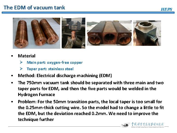
The EDM of vacuum tank HEPS • Material Ø Main part: oxygen-free copper Ø Taper part: stainless steel • Method: Electrical discharge machining (EDM) • The 750 mm vacuum tank should be separated with three main and two taper parts for EDM, and then the five parts would be welded in the Hydrogen Furnace • Problem: For the 50 mm transition parts, the local taper is too small for the 0. 25 mm-thick cutting wire. So the model had to change a little to fit the EDM, but the deviation reached 0. 2 mm. We need to improve the technique further
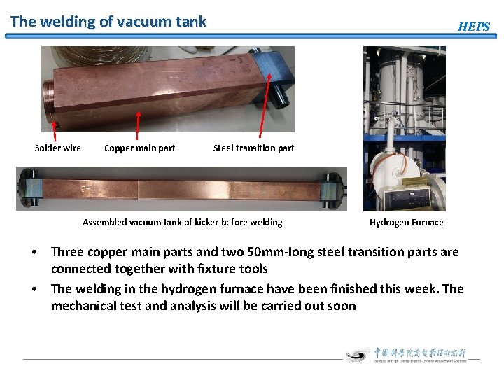
The welding of vacuum tank Solder wire Copper main part HEPS Steel transition part Assembled vacuum tank of kicker before welding Hydrogen Furnace • Three copper main parts and two 50 mm-long steel transition parts are connected together with fixture tools • The welding in the hydrogen furnace have been finished this week. The mechanical test and analysis will be carried out soon
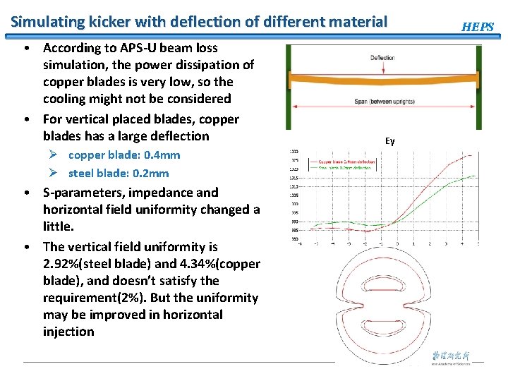
Simulating kicker with deflection of different material • According to APS-U beam loss simulation, the power dissipation of copper blades is very low, so the cooling might not be considered • For vertical placed blades, copper blades has a large deflection Ø copper blade: 0. 4 mm Ø steel blade: 0. 2 mm • S-parameters, impedance and horizontal field uniformity changed a little. • The vertical field uniformity is 2. 92%(steel blade) and 4. 34%(copper blade), and doesn’t satisfy the requirement(2%). But the uniformity may be improved in horizontal injection Ey HEPS
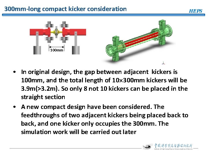
300 mm-long compact kicker consideration HEPS 100 mm • In original design, the gap between adjacent kickers is 100 mm, and the total length of 10 300 mm kickers will be 3. 9 m(>3. 2 m). So only 8 not 10 kickers can be placed in the straight section • A new compact design have been considered. The feedthroughs of two adjacent kickers being placed back to back, and one kicker only occupies the 300 mm. The simulation work will be carried out later
Summary HEPS • HEPS now consider on-axial injection. The kickers design satisfied both injection schemes Ø Injection section: 10 300 mm kickers Ø Another straight section: 4 750 mm kickers • 750 mm-long stripline kicker design have been done, but need further optimization • Mechanical fabrication Ø Copper blades may be considered for very low heat loss(w/o cooling). But the precision of CNC machining should be improved Ø For vacuum tank, the fabrication technique of EDM and hydrogen furnace welding will be investigated Ø The horizontal injection may improve the bad vertical field uniformity caused by deflection of copper blades • 300 mm-long compact kicker design will be investigated later
Thanks for your attention!