
Programming the PIC 16 F 877 in PIC

- Slides: 28
Programming the PIC 16 F 877 in PIC MPASM Assembly Language 5/21/2021 ECE 331 PIC Assembly (KEH) 1
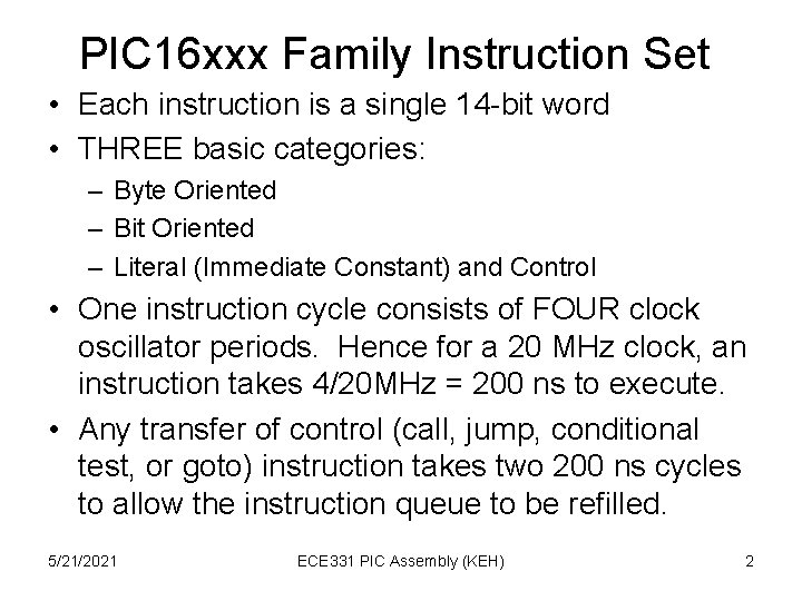
PIC 16 xxx Family Instruction Set • Each instruction is a single 14 -bit word • THREE basic categories: – Byte Oriented – Bit Oriented – Literal (Immediate Constant) and Control • One instruction cycle consists of FOUR clock oscillator periods. Hence for a 20 MHz clock, an instruction takes 4/20 MHz = 200 ns to execute. • Any transfer of control (call, jump, conditional test, or goto) instruction takes two 200 ns cycles to allow the instruction queue to be refilled. 5/21/2021 ECE 331 PIC Assembly (KEH) 2
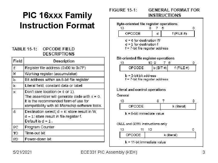
PIC 16 xxx Family Instruction Format 5/21/2021 ECE 331 PIC Assembly (KEH) 3
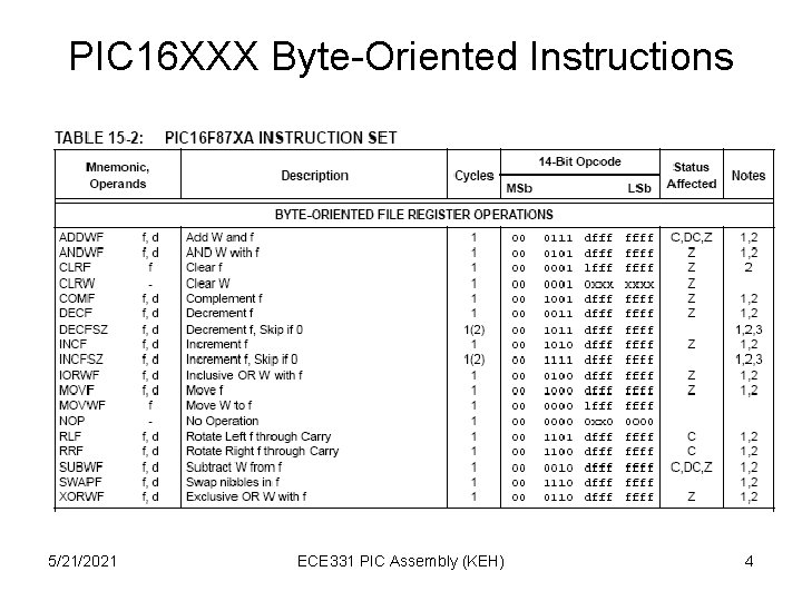
PIC 16 XXX Byte-Oriented Instructions 5/21/2021 ECE 331 PIC Assembly (KEH) 4
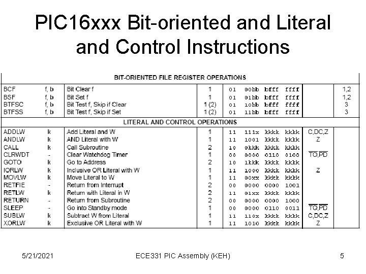
PIC 16 xxx Bit-oriented and Literal and Control Instructions 5/21/2021 ECE 331 PIC Assembly (KEH) 5
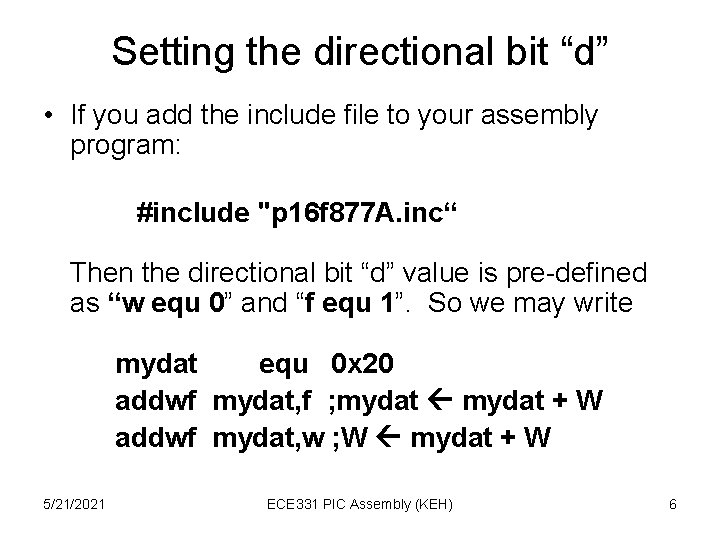
Setting the directional bit “d” • If you add the include file to your assembly program: #include "p 16 f 877 A. inc“ Then the directional bit “d” value is pre-defined as “w equ 0” and “f equ 1”. So we may write mydat equ 0 x 20 addwf mydat, f ; mydat + W addwf mydat, w ; W mydat + W 5/21/2021 ECE 331 PIC Assembly (KEH) 6
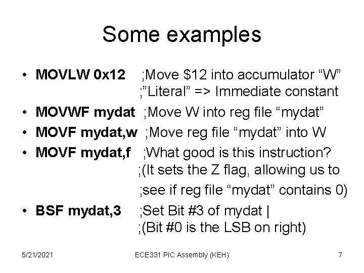
Some examples • MOVLW 0 x 12 • • ; Move $12 into accumulator “W” ; ”Literal” => Immediate constant MOVWF mydat ; Move W into reg file “mydat” MOVF mydat, w ; Move reg file “mydat” into W MOVF mydat, f ; What good is this instruction? ; (It sets the Z flag, allowing us to ; see if reg file “mydat” contains 0) BSF mydat, 3 ; Set Bit #3 of mydat | ; (Bit #0 is the LSB on right) 5/21/2021 ECE 331 PIC Assembly (KEH) 7
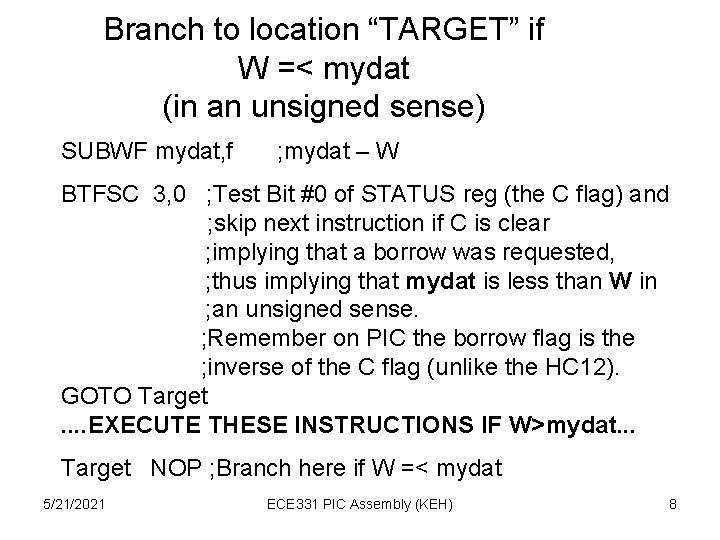
Branch to location “TARGET” if W =< mydat (in an unsigned sense) SUBWF mydat, f ; mydat – W BTFSC 3, 0 ; Test Bit #0 of STATUS reg (the C flag) and ; skip next instruction if C is clear ; implying that a borrow was requested, ; thus implying that mydat is less than W in ; an unsigned sense. ; Remember on PIC the borrow flag is the ; inverse of the C flag (unlike the HC 12). GOTO Target. . EXECUTE THESE INSTRUCTIONS IF W>mydat. . . Target NOP ; Branch here if W =< mydat 5/21/2021 ECE 331 PIC Assembly (KEH) 8
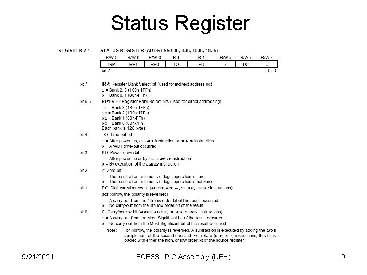
Status Register 5/21/2021 ECE 331 PIC Assembly (KEH) 9
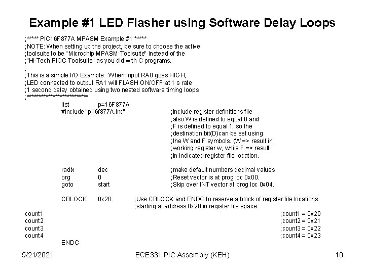
Example #1 LED Flasher using Software Delay Loops ; ***** PIC 16 F 877 A MPASM Example #1 ***** ; NOTE: When setting up the project, be sure to choose the active ; toolsuite to be "Microchip MPASM Toolsuite" instead of the ; "Hi-Tech PICC Toolsuite" as you did with C programs. ; ; This is a simple I/O Example. When input RA 0 goes HIGH, ; LED connected to output RA 1 will FLASH ON/OFF at 1 s rate ; 1 second delay obtained using two nested software timing loops ; ************* list p=16 F 877 A #include "p 16 f 877 A. inc" ; include register definitions file ; also W is defined to equal 0 and ; F is defined to equal 1, so the ; destination bit(D)can be set using ; the W and F symbols. (W => result in ; working register w, while F => result ; in indicated register file location. radix org goto dec 0 start CBLOCK 0 x 20 count 1 count 2 count 3 count 4 ; make default numbers decimal values ; Reset vector is at prog loc 0 x 00. ; Skip over INT vector at prog loc 0 x 04. ; Use CBLOCK and ENDC to reserve a block of register file locations ; starting at address 0 x 20 in register file space ; count 1 = 0 x 20 ; count 2 = 0 x 21 ; count 3 = 0 x 22 ; count 4 = 0 x 23 ENDC 5/21/2021 ECE 331 PIC Assembly (KEH) 10
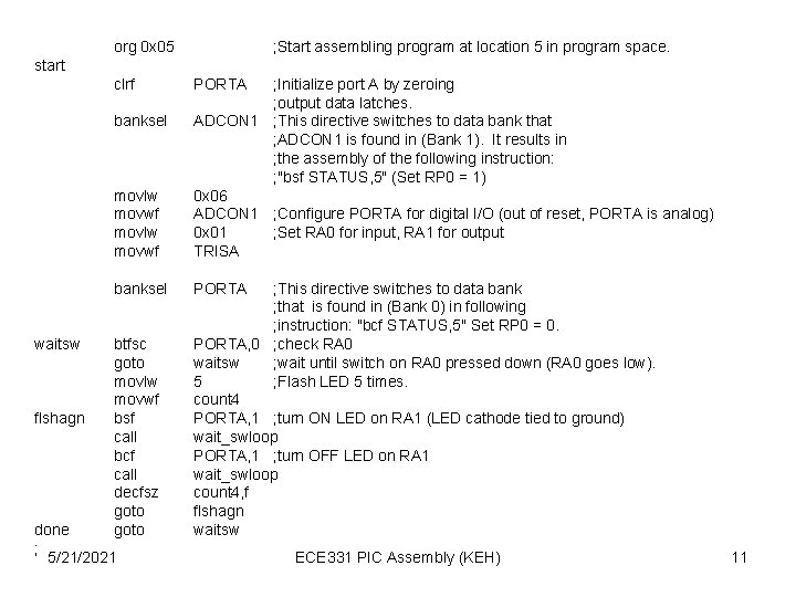
org 0 x 05 ; Start assembling program at location 5 in program space. start clrf movlw movwf ; Initialize port A by zeroing ; output data latches. ADCON 1 ; This directive switches to data bank that ; ADCON 1 is found in (Bank 1). It results in ; the assembly of the following instruction: ; "bsf STATUS, 5" (Set RP 0 = 1) 0 x 06 ADCON 1 ; Configure PORTA for digital I/O (out of reset, PORTA is analog) 0 x 01 ; Set RA 0 for input, RA 1 for output TRISA banksel PORTA banksel waitsw flshagn btfsc goto movlw movwf bsf call bcf call decfsz goto done ; 5/21/2021 PORTA ; This directive switches to data bank ; that is found in (Bank 0) in following ; instruction: "bcf STATUS, 5" Set RP 0 = 0. PORTA, 0 ; check RA 0 waitsw ; wait until switch on RA 0 pressed down (RA 0 goes low). 5 ; Flash LED 5 times. count 4 PORTA, 1 ; turn ON LED on RA 1 (LED cathode tied to ground) wait_swloop PORTA, 1 ; turn OFF LED on RA 1 wait_swloop count 4, f flshagn waitsw ECE 331 PIC Assembly (KEH) 11
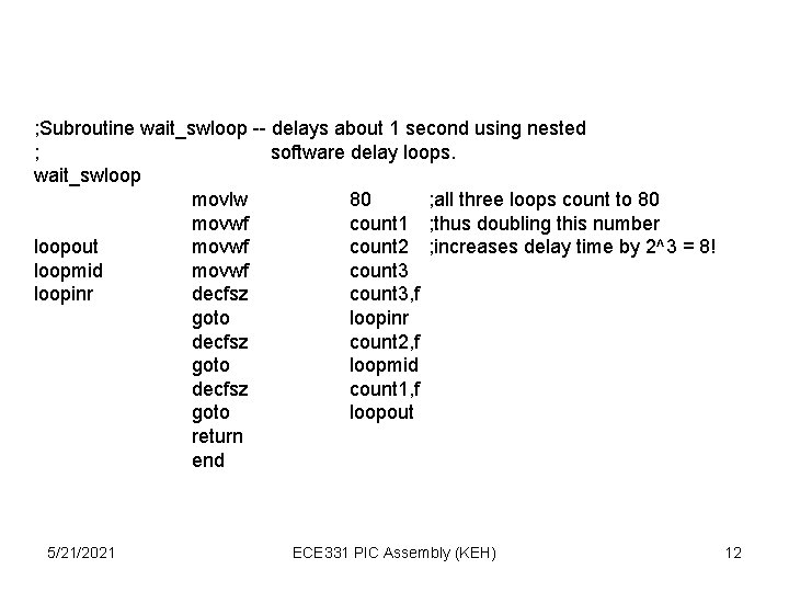
; Subroutine wait_swloop -- delays about 1 second using nested ; software delay loops. wait_swloop movlw 80 ; all three loops count to 80 movwf count 1 ; thus doubling this number loopout movwf count 2 ; increases delay time by 2^3 = 8! loopmid movwf count 3 loopinr decfsz count 3, f goto loopinr decfsz count 2, f goto loopmid decfsz count 1, f goto loopout return end 5/21/2021 ECE 331 PIC Assembly (KEH) 12
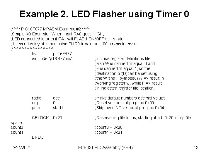
Example 2. LED Flasher using Timer 0 ; ***** PIC 16 F 877 MPASM Example #2 ***** ; Simple I/O Example. When input RA 0 goes HIGH, ; LED connected to output RA 1 will FLASH ON/OFF at 1 s rate ; 1 second delay obtained using TMR 0 to wait out 100 ten-ms intervals ; ************* list p=16 F 877 #include "p 16 f 877. inc" ; include register definitions file ; also W is defined to equal 0 and ; F is defined to equal 1, so the ; destination bit(D)can be set using ; the W and F symbols. (W => result in ; working register w, while F => result ; in indicated register file location. radix org goto dec 0 start 1 ; make default numbers decimal values ; Reset vector is at prog loc 0 x 00. ; Skip over INT vector at prog loc 0 x 04. CBLOCK 0 x 20 ; Reserve reg file locns, starting at adr 0 x 20 in reg file space count 3 count 4 ; count 3 = 0 x 20 ; count 4 = 0 x 21 ENDC 5/21/2021 ECE 331 PIC Assembly (KEH) 13
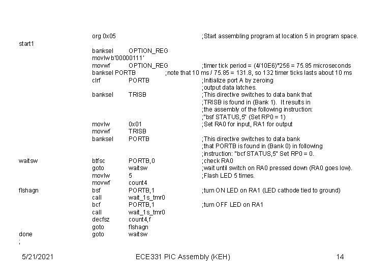
org 0 x 05 ; Start assembling program at location 5 in program space. start 1 waitsw flshagn done ; 5/21/2021 banksel OPTION_REG movlw b'00000111' movwf OPTION_REG ; timer tick period = (4/10 E 6)*256 = 75. 85 microseconds banksel PORTB ; note that 10 ms / 75. 85 = 131. 8, so 132 timer ticks lasts about 10 ms clrf PORTB ; Initialize port A by zeroing ; output data latches. banksel TRISB ; This directive switches to data bank that ; TRISB is found in (Bank 1). It results in ; the assembly of the following instruction: ; "bsf STATUS, 5" (Set RP 0 = 1) movlw 0 x 01 ; Set RA 0 for input, RA 1 for output movwf TRISB banksel PORTB ; This directive switches to data bank ; that PORTB is found in (Bank 0) in following ; instruction: "bcf STATUS, 5" Set RP 0 = 0. btfsc PORTB, 0 ; check RA 0 goto waitsw ; wait until switch on RA 0 pressed down (RA 0 goes low). movlw 5 ; Flash LED 5 times. movwf count 4 bsf PORTB, 1 ; turn ON LED on RA 1 (LED cathode tied to ground) call wait_1 s_tmr 0 bcf PORTB, 1 ; turn OFF LED on RA 1 call wait_1 s_tmr 0 decfsz count 4, f goto flshagn goto waitsw ECE 331 PIC Assembly (KEH) 14
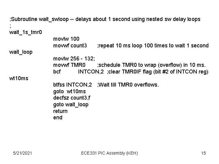
; Subroutine wait_swloop -- delays about 1 second using nested sw delay loops ; wait_1 s_tmr 0 movlw 100 movwf count 3 ; repeat 10 ms loop 100 times to wait 1 second wait_loop movlw 256 - 132; movwf TMR 0 ; schedule TMR 0 to wrap (overflow) in 10 ms. bcf INTCON, 2 ; clear TMR 0 IF flag (bit #2 of INTCON reg) wt 10 ms btfss INTCON, 2 ; Wait till TMR 0 overflows. goto wt 10 ms decfsz count 3, f goto wait_loop return end 5/21/2021 ECE 331 PIC Assembly (KEH) 15
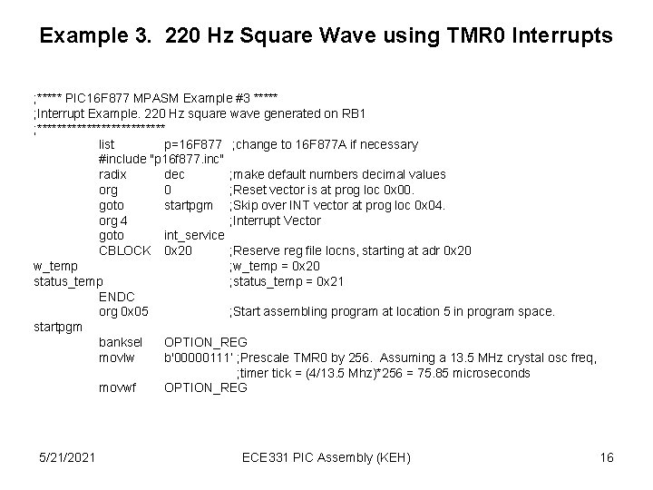
Example 3. 220 Hz Square Wave using TMR 0 Interrupts ; ***** PIC 16 F 877 MPASM Example #3 ***** ; Interrupt Example. 220 Hz square wave generated on RB 1 ; ************* list p=16 F 877 ; change to 16 F 877 A if necessary #include "p 16 f 877. inc" radix dec ; make default numbers decimal values org 0 ; Reset vector is at prog loc 0 x 00. goto startpgm ; Skip over INT vector at prog loc 0 x 04. org 4 ; Interrupt Vector goto int_service CBLOCK 0 x 20 ; Reserve reg file locns, starting at adr 0 x 20 w_temp ; w_temp = 0 x 20 status_temp ; status_temp = 0 x 21 ENDC org 0 x 05 ; Start assembling program at location 5 in program space. startpgm banksel OPTION_REG movlw b'00000111‘ ; Prescale TMR 0 by 256. Assuming a 13. 5 MHz crystal osc freq, ; timer tick = (4/13. 5 Mhz)*256 = 75. 85 microseconds movwf OPTION_REG 5/21/2021 ECE 331 PIC Assembly (KEH) 16
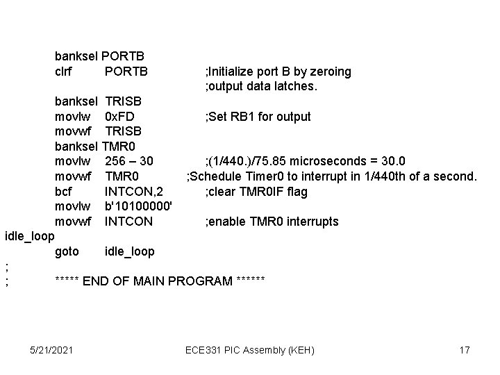
banksel PORTB clrf PORTB ; Initialize port B by zeroing ; output data latches. banksel TRISB movlw 0 x. FD ; Set RB 1 for output movwf TRISB banksel TMR 0 movlw 256 – 30 ; (1/440. )/75. 85 microseconds = 30. 0 movwf TMR 0 ; Schedule Timer 0 to interrupt in 1/440 th of a second. bcf INTCON, 2 ; clear TMR 0 IF flag movlw b'10100000' movwf INTCON ; enable TMR 0 interrupts idle_loop goto idle_loop ; ; ***** END OF MAIN PROGRAM ****** 5/21/2021 ECE 331 PIC Assembly (KEH) 17
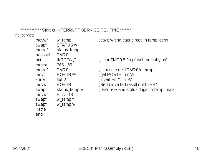
; ******* Start of INTERRUPT SERVICE ROUTINE ******* int_service movwf w_temp ; save w and status regs in temp locns swapf STATUS, w movwf status_temp banksel TMR 0 bcf INTCON, 2 ; clear TMR 0 IF flag (shut the baby up) movlw 256 - 30 movwf TMR 0 ; schedule next TMR 0 interrupt movf PORTB, W ; get PORTB into W xorlw 0 x 02 ; invert Bit #1 of W movwf PORTB ; Send inverted result out to RB 1 swapf status_temp, w ; restore w and status flags fm temp locns movwf STATUS swapf w_temp, f swapf w_temp, w retfie end 5/21/2021 ECE 331 PIC Assembly (KEH) 18
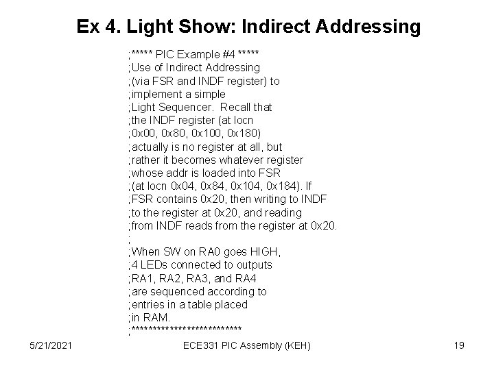
Ex 4. Light Show: Indirect Addressing ; ***** PIC Example #4 ***** ; Use of Indirect Addressing ; (via FSR and INDF register) to ; implement a simple ; Light Sequencer. Recall that ; the INDF register (at locn ; 0 x 00, 0 x 80, 0 x 100, 0 x 180) ; actually is no register at all, but ; rather it becomes whatever register ; whose addr is loaded into FSR ; (at locn 0 x 04, 0 x 84, 0 x 104, 0 x 184). If ; FSR contains 0 x 20, then writing to INDF ; to the register at 0 x 20, and reading ; from INDF reads from the register at 0 x 20. ; ; When SW on RA 0 goes HIGH, ; 4 LEDs connected to outputs ; RA 1, RA 2, RA 3, and RA 4 ; are sequenced according to ; entries in a table placed ; in RAM. ; ************* 5/21/2021 ECE 331 PIC Assembly (KEH) 19
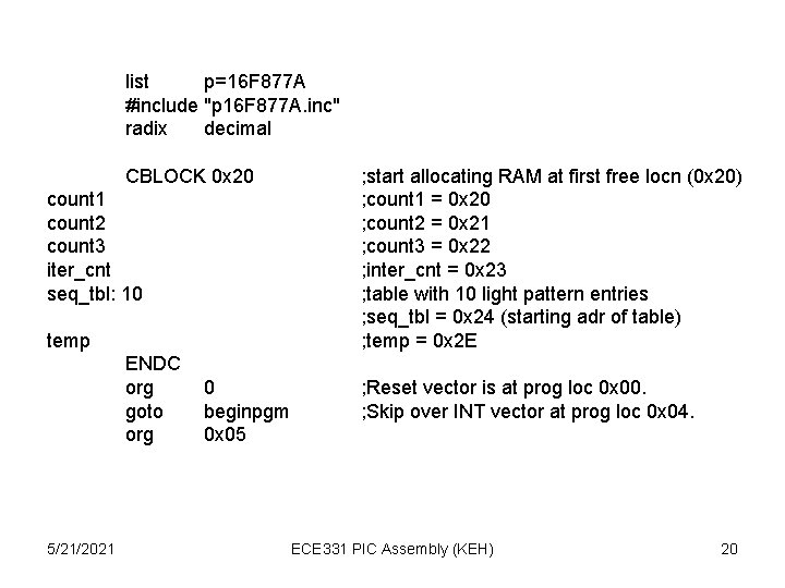
list p=16 F 877 A #include "p 16 F 877 A. inc" radix decimal CBLOCK 0 x 20 count 1 count 2 count 3 iter_cnt seq_tbl: 10 temp ENDC org goto org 5/21/2021 0 beginpgm 0 x 05 ; start allocating RAM at first free locn (0 x 20) ; count 1 = 0 x 20 ; count 2 = 0 x 21 ; count 3 = 0 x 22 ; inter_cnt = 0 x 23 ; table with 10 light pattern entries ; seq_tbl = 0 x 24 (starting adr of table) ; temp = 0 x 2 E ; Reset vector is at prog loc 0 x 00. ; Skip over INT vector at prog loc 0 x 04. ECE 331 PIC Assembly (KEH) 20
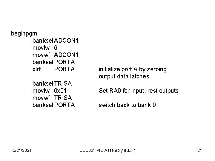
beginpgm banksel ADCON 1 movlw 6 movwf ADCON 1 banksel PORTA clrf PORTA banksel TRISA movlw 0 x 01 movwf TRISA banksel PORTA 5/21/2021 ; initialize port A by zeroing ; output data latches. ; Set RA 0 for input, rest outputs ; switch back to bank 0 ECE 331 PIC Assembly (KEH) 21
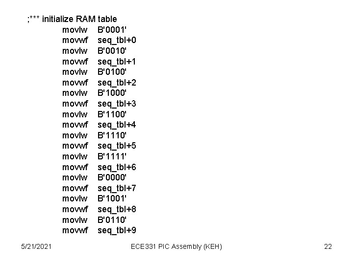
; *** initialize RAM table movlw B'0001' movwf seq_tbl+0 movlw B'0010' movwf seq_tbl+1 movlw B'0100' movwf seq_tbl+2 movlw B'1000' movwf seq_tbl+3 movlw B'1100' movwf seq_tbl+4 movlw B'1110' movwf seq_tbl+5 movlw B'1111' movwf seq_tbl+6 movlw B'0000' movwf seq_tbl+7 movlw B'1001' movwf seq_tbl+8 movlw B'0110' movwf seq_tbl+9 5/21/2021 ECE 331 PIC Assembly (KEH) 22
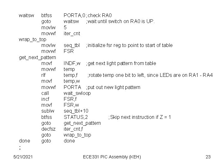
waitsw btfss goto movlw movwf wrap_to_top movlw movwf get_next_pattern movf movwf rlf movwf call incf movf sublw btfss goto decfsz goto done goto PORTA, 0 ; check RA 0 waitsw ; wait until switch on RA 0 is UP. 5 iter_cnt seq_tbl FSR ; initialize fsr reg to point to start of table INDF, w ; get next light pattern from table temp, f ; rotate temp one bit to left, since LEDs are on RA 1 - RA 4 temp, w PORTA ; put out new light pattern wait_swloop FSR, f FSR, w seq_tbl+10 STATUS, 2 ; Skip next instruction if Z = 1 get_next_pattern iter_cnt, f wrap_to_top done ; 5/21/2021 ECE 331 PIC Assembly (KEH) 23
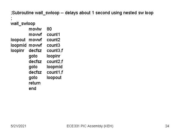
; Subroutine wait_swloop -- delays about 1 second using nested sw loop ; wait_swloop movlw 80 movwf count 1 loopout movwf count 2 loopmid movwf count 3 loopinr decfsz count 3, f goto loopinr decfsz count 2, f goto loopmid decfsz count 1, f goto loopout return end 5/21/2021 ECE 331 PIC Assembly (KEH) 24
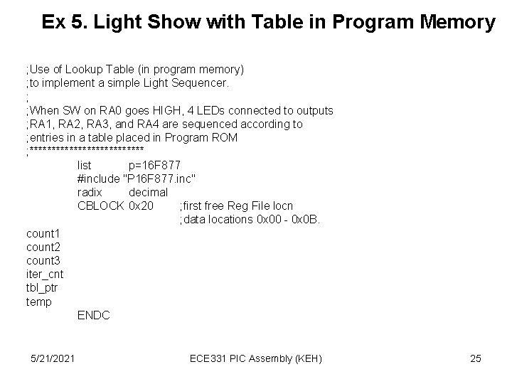
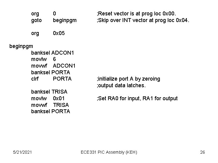
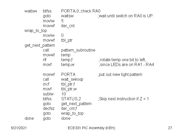
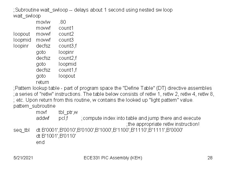
Ex 5. Light Show with Table in Program Memory ; Use of Lookup Table (in program memory) ; to implement a simple Light Sequencer. ; ; When SW on RA 0 goes HIGH, 4 LEDs connected to outputs ; RA 1, RA 2, RA 3, and RA 4 are sequenced according to ; entries in a table placed in Program ROM ; ************* list p=16 F 877 #include "P 16 F 877. inc" radix decimal CBLOCK 0 x 20 ; first free Reg File locn ; data locations 0 x 00 - 0 x 0 B. count 1 count 2 count 3 iter_cnt tbl_ptr temp ENDC 5/21/2021 ECE 331 PIC Assembly (KEH) 25
org goto 0 beginpgm org 0 x 05 beginpgm banksel ADCON 1 movlw 6 movwf ADCON 1 banksel PORTA clrf PORTA banksel TRISA movlw 0 x 01 movwf TRISA banksel PORTA 5/21/2021 ; Reset vector is at prog loc 0 x 00. ; Skip over INT vector at prog loc 0 x 04. ; initialize port A by zeroing ; output data latches. ; Set RA 0 for input, RA 1 for output ECE 331 PIC Assembly (KEH) 26
waitsw btfss goto movlw movwf wrap_to_top movlw movwf get_next_pattern call movwf rlf movf done 5/21/2021 movwf call incf movf sublw btfss goto decfsz goto PORTA, 0 ; check RA 0 waitsw ; wait until switch on RA 0 is UP. 5 iter_cnt 0 tbl_ptr pattern_subroutine temp, f ; rotate temp one bit to left, temp, w ; since LEDs are on RA 1 - RA 4 PORTA wait_swloop tbl_ptr, f tbl_ptr, w 10 STATUS, 2 get_next_pattern iter_cnt, f wrap_to_top done ; put out new light pattern ; Skip next instruction if Z = 1 ECE 331 PIC Assembly (KEH) 27
; Subroutine wait_swloop -- delays about 1 second using nested sw loop wait_swloop movlw. 80 movwf count 1 loopout movwf count 2 loopmid movwf count 3 loopinr decfsz count 3, f goto loopinr decfsz count 2, f goto loopmid decfsz count 1, f goto loopout return ; Pattern lookup table - part of program space the "Define Table" (DT) directive assembles ; a series of "retlw" instructions. The table below consists of retlw 1, retlw 2, retlw 4, retlw 8, ; etc. Upon return from this routine, w contains the looked up "light pattern" value. pattern_subroutine movf tbl_ptr, w addwf pcl, f ; compute index into table and jump there and execute ; the appropriate retlw instruction! seq_tbl dt B'0001', B'0010', B'0100', B'1000', B'1110', B'1111', B'0000' dt B'1001', B'0110' end 5/21/2021 ECE 331 PIC Assembly (KEH) 28