
Programabilni hardver i ugraeni sistemi Predavanje 0102 profesor
Programabilni hardver i ugrađeni sistemi Predavanje 01_02 profesor: Prof. Dr Petar Spalević email: pspalevic@singidunum. ac. rs autor rukopisa: Prof. dr Vladimir Matić Kurs je podržan od kompanije Mikro. Elektronika
Mikrokontroler vs. mikroprocesor • Razlika između mikrokontrolera i mikroprocesora
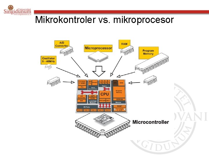
Mikrokontroler vs. mikroprocesor
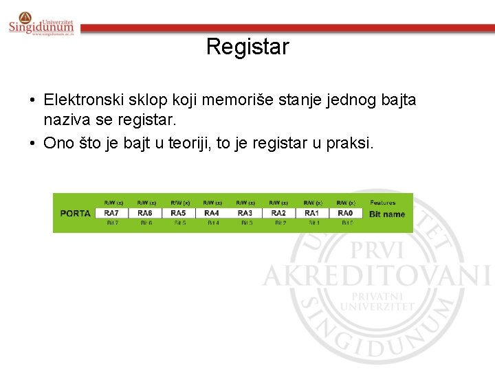
Registar • Elektronski sklop koji memoriše stanje jednog bajta naziva se registar. • Ono što je bajt u teoriji, to je registar u praksi.
Registar
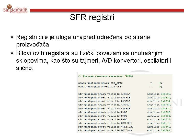
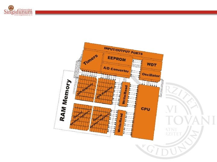
SFR registri • Registri čije je uloga unapred određena od strane proizvođača • Bitovi ovih registara su fizički povezani sa unutrašnjim sklopovima, kao što su tajmeri, A/D konvertori, oscilatori i slično.
SFR registri
Ulazno-izlazni portovi • Da bi mikrokontroler imao korisnu primenu, on mora biti povezan sa spoljnim svetom • Svaki mikrokontroler ima jedan ili više registara (u ovom slučaju se zovu portovi) i oni su povezani sa izvodima na kućištu • Zovu se ulazno-izlazni jer se njihova uloga programski može menjati • Maksimalna struja (10 -20 m. A) • Pull-up otpornici
Ulazno-izlazni portovi
primer • Usually, each I/O port is under control of another SFR, which means that each bit of that register determines state of the corresponding microcontroller pin. For example, by writing logic one (1) to one bit of that control register SFR, the appropriate port pin is automatically configured as intput. It means that voltage brought to that pin can be read as logic 0 or 1. Otherwise, by writing zero to the SFR, the appropriate port pin is configured as output. Its voltage (0 V or 5 V) corresponds to the state of the appropriate bit of the port register.
Memorijska jedinica

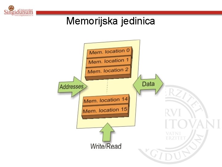
Memorijska jedinica • Memorija je deo mikrokontrolera u kome se čuvaju podaci • Programska ili ROM memorija (Read Only Memory) – 16 -bitno adresiranje obezbedjuje 65535 lokacija. • Flash memorija • Radna ili RAM memorija (Random Access Memory) • EEPROM memorija (Electrically Erasable Programmable ROM) – Sadržaj ostaje u memoriji i posle isključenja napajanja • Interapt
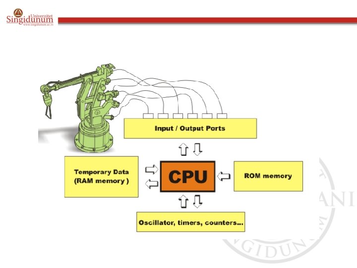
Centralna Procesorska Jedinica - CPU • Dekoder instrukcija • Aritmetičko logička jedinica (ALU) • Akumulator
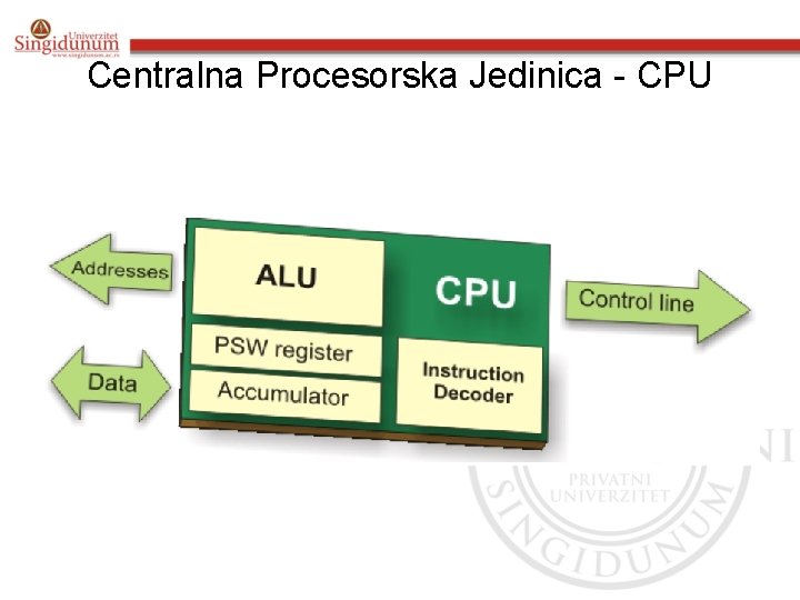
Centralna Procesorska Jedinica - CPU
• Instruction Decoder is a part of electronics which recognizes program instructions and runs other circuits on the basis of that. The “instruction set” which is different for each microcontroller family expresses the abilities of this circuit.
• Arithmetical Logical Unit (ALU) performs all mathematical and logical operations upon data. • Accumulator is a SFR closely related to the operation of ALU. It is a kind of working desk used for storing all data upon which some operation should be performed (addition, shift/move etc. ). It also stores results ready for use in further processing. One of SFRs, called Status Register (PSW), is closely related to the accumulator. It shows at any moment the “status” of a number stored in the accumulator (number is greater or less than zero etc. ).
Magistrala • Magistrala predstavlja skup od 8, 16 ili više provodnika • postoje: – Adresna i magistrala podataka • Adresna se sastoji od onoliko linija koliko je potrebno za adresiranje memorije. • Magistrala je široka koliko i podatak, a u našem slučaju to je 8 bita i ona povezuje sve blokove unutar mikrokontrolera

Serijska komunikacija
Serijska komunikacija • Mikrokontroler ostvaruje vezu sa ulazno-izlaznim portovima • Kada je komunikacija na većim rastojanjima potrebno je obezbediti serijsku vezu • bitni faktori su: – Broj uređaja sa kojima se razmenjuju podaci – Kolika mora da bude brzina prenosa podataka ? – Kolika je udaljenost između uređaja ? – Da li se podaci istovremeno i šalju i primaju ?
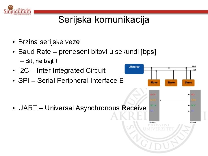
Serijska komunikacija • Brzina serijske veze • Baud Rate – preneseni bitovi u sekundi [bps] – Bit, ne bajt ! • I 2 C – Inter Integrated Circuit • SPI – Serial Peripheral Interface Bus • UART – Universal Asynchronous Receiver/Transmitter
Baud rate • It is usually required by the protocol that each byte is transferred along with several control bits. It means that one byte in serial data stream may 18 consist of 11 bits. For example, if the baud rate is 300 bps then maximum 37 and minimum 27 bytes may be transferred per second, which depends on type of connection and protocol in use.
I 2 C
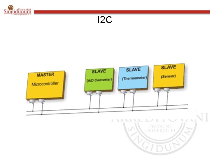
I 2 C • I 2 C (Inter Integrated Circuit) is a system used when the distance between the microcontrollers is short and specialized integrated circuits of a new generation (receiver and transmitter are usually on the same printed circuit board). Connection is established via two conductors- one is used for data transfer whereas another is used for synchronization (clock signal). As seen in figure, in such connection, one device is always master. It performs addressing of one slave chip (subordinated) before communication starts. In this way one microcontroller can communicate with 112 different devices.
SPI
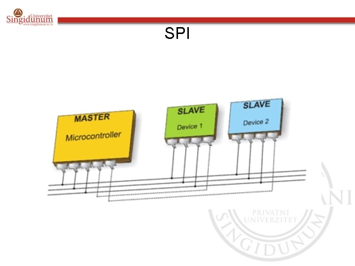
SPI • SPI (Serial Peripheral Interface Bus) is a system for serial communication which uses four conductors (usually three)- one for data receiving, one for data sending, one for synchronization and one (alternatively) for selecting device to communicate with. It is full duplex connection, which means that data are sent and received simultaneously. Maximal baud rate is higher than in I 2 C connection.
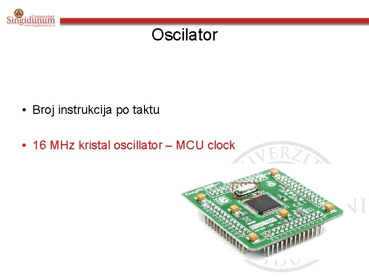
Oscilator • Broj instrukcija po taktu • 16 MHz kristal oscillator – MCU clock
Oscilator
Oscillator • Even pulses coming from the oscillator enable harmonic and synchronous operation of all circuits of the microcontroller. The oscillator module is usually configured to use quartz crystal or ceramic resonator frequency stabilization. • It is important to say that instructions are not executed at the rate imposed by the oscillator itself, but several times slower. It happens because each instruction is executed in several steps.
Kolo za napajanje • Brown out • Pin za reset
• There are two things worth attention concerning the microcontroller power supply circuit: Brown out is a potentially dangerous state which occurs at the moment the microcontroller is being turned off or in situations when power supply voltage drops to the limit due to powerful electric noises. As the microcontroller consists of several circuits which have different operating voltage levels, this state can cause its out-of-control performance. • In order to prevent it, the microcontroller usually has builtin circuit for brown out reset. This circuit immediately resets the whole electronics when the voltage level drops below the limit.
• Reset pin is usually marked as MCLR (Master Clear Reset) and serves for external reset of the microcontroller by applying logic zero (0) or one (1), depending on type of the microcontroller. In case the brown out circuit is not built in, a simple external circuit for brown out reset can be connected to this pin.
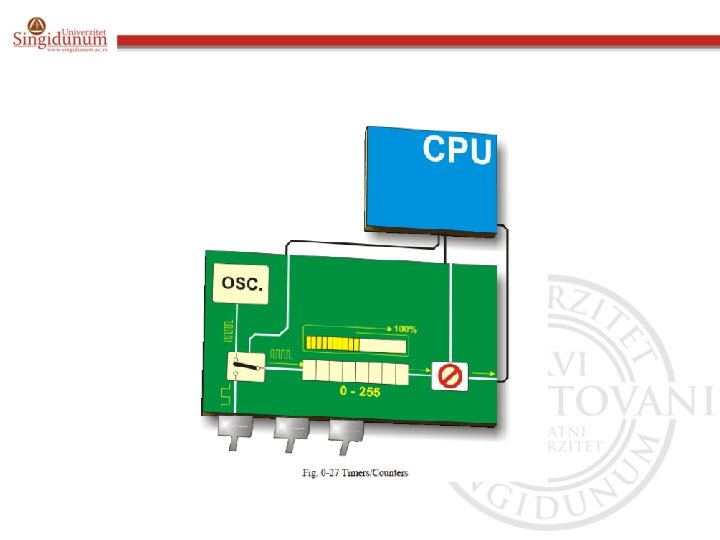
Tajmeri / brojači • Kvarcni kristal – Impulsi stabilni i iste širine – Idealno za merenje vremena • Engl. If it is necessary to measure time passed between two events, it is just enough to count pulses coming from this oscillator. That is exactly what the timer does. • Tipičan tajmer mikrokontrolera
Tajmeri / brojači • Kako rade tajmeri ?
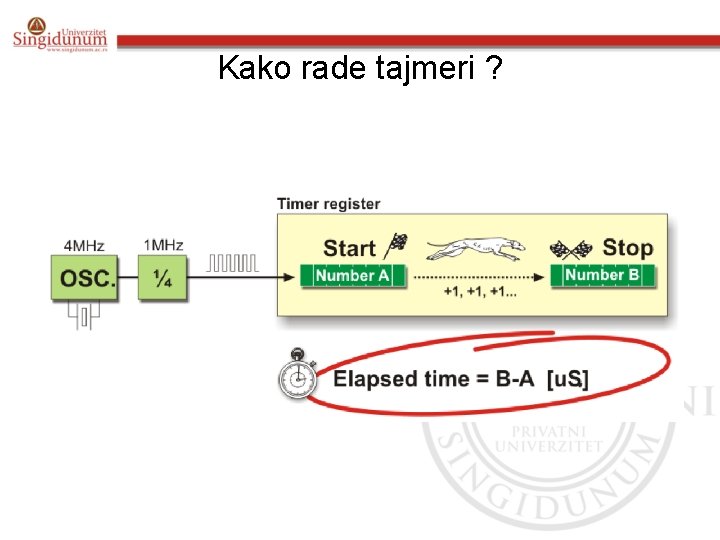
Kako rade tajmeri ?
• In practice, everything works as follows: pulses coming from quartz oscillator are once per each machine cycle directly or via prescaler brought to the circuit which increments number in the timer register. If one instruction (one machine cycle) lasts for four quartz oscillator periods then, by embedding quartz with the frequency of 4 MHz, this number will be changed a million times per second (each microsecond).

Upotreba preskalera u radu tajmera
Tajmeri / brojači • Upotreba prekida u radu tajmera
Watchdog tajmer • Svaki program na mikrokontroleru se sastoji od petlje koja se ponavlja • Program treba da obezbedi da se redovno resetuje stanje watchdog timera i sve se obavlja u predviđenom redu. • Ukoliko se program “zaglavi” u nekoj memorijskoj lokaciji, tada će brojač – watchdog tajmera dostići maksimum i rad mikrokontrolera će se resetovati

A/D konvertor • Prevođenje analognog napona u digitalni koji se dalje koristi i obrađuje u programu

Internal Architecture • All upgraded microcontrollers use one of two basic design models called Harvard and von-Neumann architecture. What is it about? • Briefly, it is about two different ways of data exchange between CPU and memory.
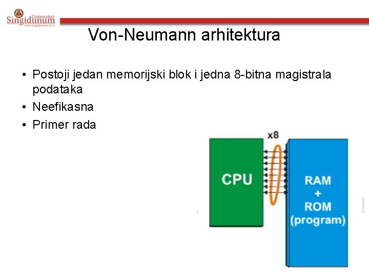
Von-Neumann arhitektura • Postoji jedan memorijski blok i jedna 8 -bitna magistrala podataka • Neefikasna • Primer rada
Harvard arhitektura • Koriste se dve magistrale podataka – 8 bita: CPU – RAM memorijom – 12, 14 ili 16 bita CPU sa ROM memorijom • Prednosti : – Podaci su od 8 bita. • Ostali bitovi predstavljaju višak koji se koristi za očitavanje instrukcija – S obzirom da su RAM i ROM razdvojeni mogu se izvršavati dve instrukcije u paraleli – Tačno poznavanje memorije koja će se koristiti
Harvard arhitektura
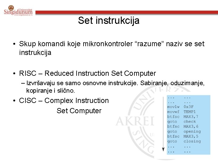
Set instrukcija • Skup komandi koje mikronkontroler “razume” naziv se set instrukcija • RISC – Reduced Instruction Set Computer – Izvršavaju se samo osnovne instrukcije. Sabiranje, oduzimanje, kopiranje i slično. • CISC – Complex Instruction Set Computer
PIC mikrokontroleri • PICmicro – Perhipheral Interface controller – Microchip Technology • Karakteristike • Tabela strana 49.

HOW TO MAKE THE RIGHT CHOICE
Mikrokontroler PIC 16 F 877
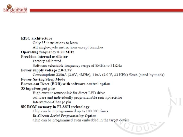
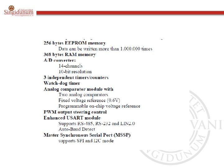
PIC 16 F 877 • Optimalne karakteristike mikrokontrolera • Pogodan za: kontrolu procesa u industriji, upravljanje mašinama i uređajima, merenje različitih veličina • Spisak karakteristika. • Tabela strana 54 -55.
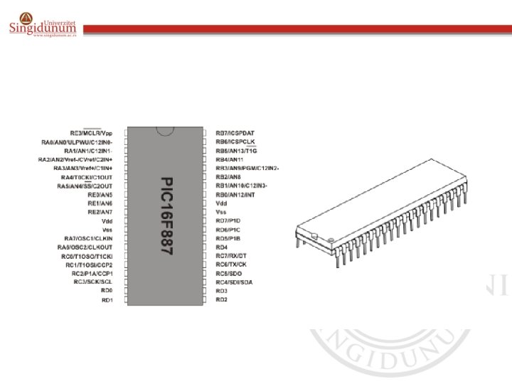
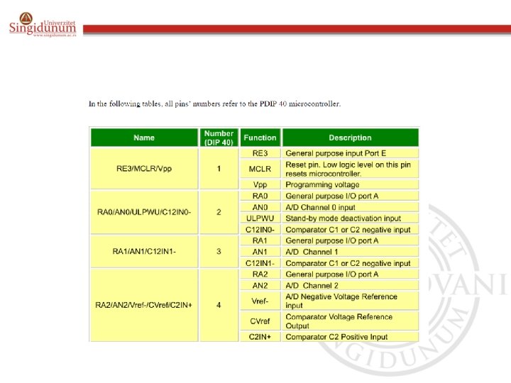
Pin Description • As seen in picture above, the most pins are multifunctional. For example, designator RA 3/AN 3/Vref+/C 1 IN+ for the fifth pin specifies the following functions: · RA 3 Port A third digital input/output · AN 3 Third analog input · Vref+ Positive voltage reference · C 1 IN+ Comparator C 1 positive input This small trick is often used because it makes the microcontroller package more compact without affecting its functionality. These various pin functions cannot be used simultaneously, but can be changed at any point during operation.


Centralna Procesorska Jedinica - CPU • RISC tehnologija – Reduced Instruction Set Computer • Prednosti PIC 16 F 877 – Njegov CPU može da prepozna i izvrši samo 35 jednostavnih instrukcija – Vreme izvršenja svake od instrukcija traje četiri ciklusa taktnog generatora
STEK • Stack se sastoji od 8 13 -bitnih registara • Kada mikrokontroler izvršava neki potprogram ili ukoliko dođe do interapta, adresa instrukcije koja se trenutno izvršava se smešta u stek
- Slides: 62