Process Data Multiplexing Demultiplexing Techniques ZANKHANA MEHTA Multiplexing


 • FDM is an analog technique that can be applied when")
 • In FDM signals generated by each device modulate different carrier")
 • In analog transmission, the sending device produces a high frequency signal")
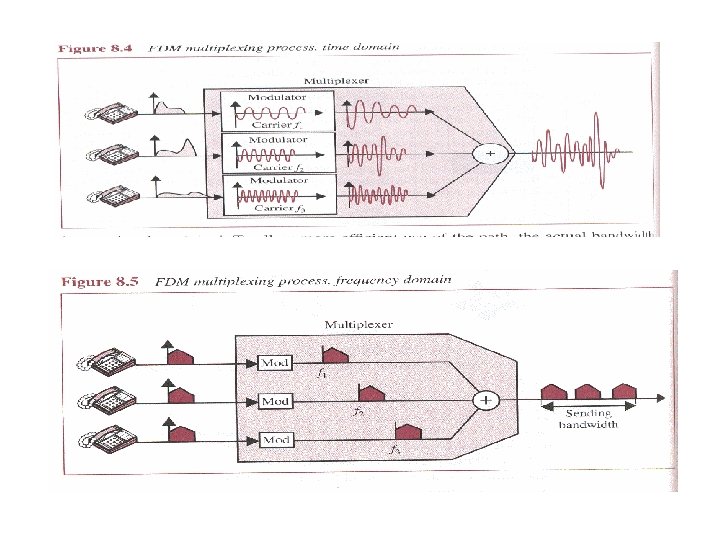
 Time-domain description")
 Frequency-domain description")
 • In FDM signals generated by each device modulate different carrier")
 • In FDM, signals are modulated onto separate carrier frequencies using")


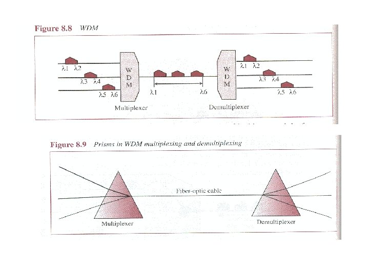
 • Wave-division multiplexing is conceptually the same as FDM, except that")
 • Time-division multiplexing (TDM) is a digital process that can be")

 • TDM can be implemented in two ways: synchronous TDM and")


 Framing Bits Because the time slot order in a synchronous TDM")


 We can answer the questions as follows: 1. The data rate of")


 Voice Channels")
 Voice Channels E-1 2.")


- Slides: 48
Process Data Multiplexing / Demultiplexing Techniques ZANKHANA MEHTA
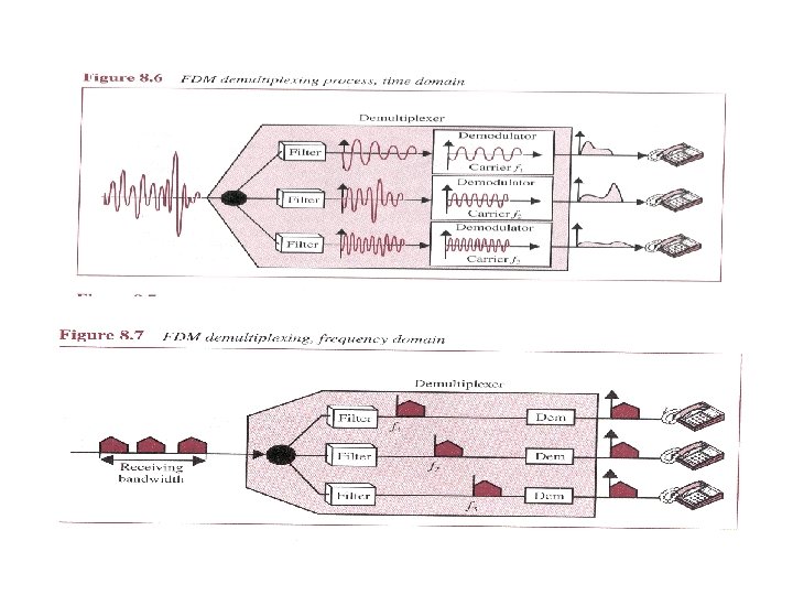
Multiplexing • Multiplexing is the set of techniques that allows the simultaneous transmission of multiple signals across a single data link. • A Multiplexer (MUX) is a device that combines several signals into a single signal. • A Demultiplexer (DEMUX) is a device that performs the inverse operation.
Categories of Multiplexing
Frequency-division Multiplexing (FDM) • FDM is an analog technique that can be applied when the bandwidth of a link is greater than the combined bandwidths of the signals to be transmitted.
Frequency-division Multiplexing (FDM) • In FDM signals generated by each device modulate different carrier frequencies. These modulated signals are combined into a single composite signal that can be transported by the link. FDM is an analog multiplexing technique that combines signals.
Modulating (Modulation) • In analog transmission, the sending device produces a high frequency signal (a sine wave) that acts as a basis for the information signal. This base signal is called the carrier signal. • Digital information is then modulated on the carrier signal by modifying one or more of its characteristics (amplitude, frequency, phase). This kind of modification is called modulation and the information signal is called a modulating signal.
Modulation (Amplitude Shift keying ASK) Time-domain description
Modulation (Amplitude Shift keying ASK) Frequency-domain description
Frequency-division Multiplexing (FDM) • In FDM signals generated by each device modulate different carrier frequencies. These modulated signals are combined into a single composite signal that can be transported by the link. • Carrier frequencies are separated by enough bandwidth to accommodate the modulated signal. • These bandwidth ranges arte the channels through which various signals travel. • Channels must separated by strips of unused bandwidth (guard bands) to prevent signal overlapping.
Frequency-division Multiplexing (FDM) • In FDM, signals are modulated onto separate carrier frequencies using either AM or FM modulation.
Example 1 Assume that a voice channel occupies a bandwidth of 4 KHz. We need to combine three voice channels into a link with a bandwidth of 12 KHz, from 20 to 32 KHz. Show the configuration using the frequency domain without the use of guard bands. Solution Shift (modulate) each of the three voice channels to a different bandwidth, as shown in Figure 6. 6.
Example 1
Example 2 Five channels, each with a 100 -KHz bandwidth, are to be multiplexed together. What is the minimum bandwidth of the link if there is a need for a guard band of 10 KHz between the channels to prevent interference? Solution For five channels, we need at least four guard bands. This means that the required bandwidth is at least 5 x 100 + 4 x 10 = 540 KHz, as shown in Figure 6. 7.
Example 2
Wave-division Multiplexing (WDM) • Wave-division multiplexing is conceptually the same as FDM, except that multiplexing and demultiplexing involve light signals transmitted through fiber-optic channels. • The purpose is to combine multiple light sources into one single light at the multiplexer and do the reverse at the demultiplexer. • Combining and splitting of light sources are easily handled by a prism.
Time-division Multiplexing (TDM) • Time-division multiplexing (TDM) is a digital process that can be applied when the data rate capacity of the transmission medium is greater than the data rate required by the sending and receiving devices.
TDM is a digital multiplexing technique to combine data.
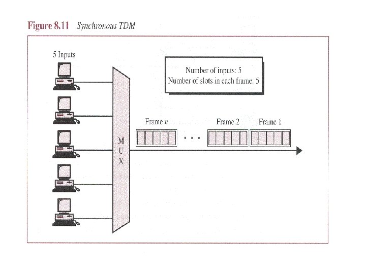
Time-division Multiplexing (TDM) • TDM can be implemented in two ways: synchronous TDM and asynchronous TDM. • In synchronous time-division multiplexing, the term synchronous means that the multiplexer allocates exactly the same time slot to each device at all times, whether or not a device has anything to transmit. • Frames Time slots are grouped into frames. A frame consists of a one complete cycle of time slots, including one or more slots dedicated to each sending device.
TDM frames
Example 5 Four 1 -Kbps connections are multiplexed together. A unit is 1 bit. Find (1) the duration of 1 bit before multiplexing, (2) the transmission rate of the link, (3) the duration of a time slot, and (4) the duration of a frame? Solution We can answer the questions as follows: 1. The duration of 1 bit is 1/1 Kbps, or 0. 001 s (1 ms). 2. The rate of the link is 4 Kbps. 3. The duration of each time slot 1/4 ms or 250 ms. 4. The duration of a frame 1 ms.
In a TDM, the data rate of the link is n times faster, and the unit duration is n times shorter.
Interleaving
Example 6 Four channels are multiplexed using TDM. If each channel sends 100 bytes/s and we multiplex 1 byte per channel, show the frame traveling on the link, the size of the frame, the duration of a frame, the frame rate, and the bit rate for the link. Solution The multiplexer is shown in Figure 6. 15.
Example 6
Example 7 A multiplexer combines four 100 -Kbps channels using a time slot of 2 bits. Show the output with four arbitrary inputs. What is the frame rate? What is the frame duration? What is the bit rate? What is the bit duration? Solution Figure 6. 16 shows the output for four arbitrary inputs.
Example 7
Time-division Multiplexing (TDM) Framing Bits Because the time slot order in a synchronous TDM system doest no vary from frame to frame, very little overhead information needs to be included in each frame. However, one or more synchronization bits are usually added to the beginning of each frame. These bits, called framing bits, allows the demultiplexer to synchronize with the incoming stream so that it can separate the time slot accurately.
Framing bits
Example Suppose that we have four input devices on a synchronous TDM link, where the transmissions are interleaved by character. If each device is generating 250 characters per second, and each frame is carrying 1 character from each device, what is the minimum data rate of this link?
The link must be able to carry 250 frames per second. If we assume that each character consists of 8 bits, then each frame has 4 x 8 + 1= 33 bits ( 32 bits for the four characters plus 1 framing bit). On the other hand, each device is creating 2000 bps, because 250 characters per second x 8 bits =2000 bits per second, and the link is carrying 8250 bps, because 250 frames per second x 33 bits is 8250 bps.
Example 8 We have four sources, each creating 250 characters per second. If the interleaved unit is a character and 1 synchronizing bit is added to each frame, find (1) the data rate of each source, (2) the duration of each character in each source, (3) the frame rate, (4) the duration of each frame, (5) the number of bits in each frame, and (6) the data rate of the link. Solution See next slide.
Solution (continued) We can answer the questions as follows: 1. The data rate of each source is 2000 bps = 2 Kbps. 2. The duration of a character is 1/250 s, or 4 ms. 3. The link needs to send 250 frames per second. 4. The duration of each frame is 1/250 s, or 4 ms. 5. Each frame is 4 x 8 + 1 = 33 bits. 6. The data rate of the link is 250 x 33, or 8250 bps.
Example 9 Two channels, one with a bit rate of 100 Kbps and another with a bit rate of 200 Kbps, are to be multiplexed. How this can be achieved? What is the frame rate? What is the frame duration? What is the bit rate of the link? Solution We can allocate one slot to the first channel and two slots to the second channel. Each frame carries 3 bits. The frame rate is 100, 000 frames per second because it carries 1 bit from the first channel. The frame duration is 1/100, 000 s, or 10 ms. The bit rate is 100, 000 frames/s x 3 bits/frame, or 300 Kbps.
DS hierarchy
Table 6. 1 DS and T lines rates Service Line Rate (Mbps) Voice Channels DS-1 T-1 1. 544 24 DS-2 T-2 6. 312 96 DS-3 T-3 44. 736 672 DS-4 T-4 274. 176 4032
Table 6. 2 E line rates E Line Rate (Mbps) Voice Channels E-1 2. 048 30 E-2 8. 448 120 E-3 34. 368 480 E-4 139. 264 1920
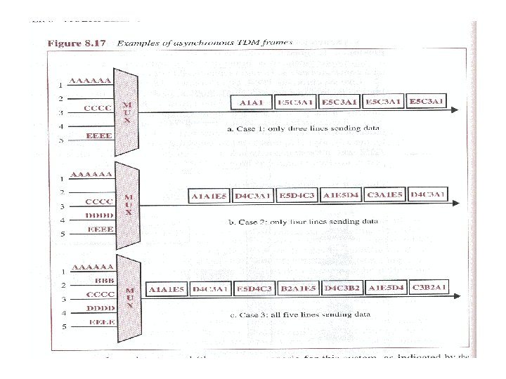
Asynchronous TDM • Synchronous TDM does not guarantee that the full capacity of a link is used. Because the time slots are preassigned and fixed, whenever a connected device is not transmitting, the corresponding slot is empty. • Asynchronous time-division multiplexing, or statistical time-division multiplexing, is designed to avoid this type of waste. • Like synchronous TDM, asynchronous TDM allows a number of lower-speed input lines to be multiplexed to a single higher-speed line. However, in asynchronous TDM the total speed of the input lines can be greater than the capacity of the link.
• In an asynchronous system, if we have n input lines, the frame contains no more than m slots, with m less than n. • The number of time slots in an asynchronous TDM frame (m) is based on statistical analysis of the number of input lines that are likely to be transmitting at any given time. • In this case any slot is available to any of the attached input lines that has data to send.
Asynchronous TDM Addressing and Overhead • In asynchronous TDM each time slot must carry an address telling the demultiplexer how direct the data. This address, for local use only, is attached by the multiplexer and discarded by the demultiplexer once it has been read. • Asynchronous TDM is efficient only when the size of the time slots kept relatively large.
Inverse Multiplexing • Inverse multiplexing takes the data stream from one highspeed line and breaks it into portions that can be sent across several lower-speed lines simultaneously, with no loss in the collective data rate.
Figure 6. 21 Multiplexing and inverse multiplexing