
PROBLEM 8 SCIFI SOUND IYPT 2019 Team Croatia

PROBLEM 8: „SCI-FI SOUND” IYPT 2019 Team Croatia
Table of contents I • Problem description II • Theoretical model III • Experimental measurments IV • Analysis of experimental results V • Conclusions
Problem description: „Tapping a helical spring can make a sound like a “laser shot” in a science-fiction movie. ” „Investigate and explain this phenomenon. ”
Table of contents I • Problem description II • Theoretical model III • Experimental measurments IV • Analysis of experimental results V • Conclusions
Hypothesis The sound of a laser shot from SF movies can be produced by causing highfrequency vibrations in a long rod or a wire, made of dispersive medium with property that the velocity of sound waves v is increased for higher frequencies and decreased for lower frequencies with an measurable delaying time TD between higher and lower part of the frequency spectrum. The delay time TD depends from …
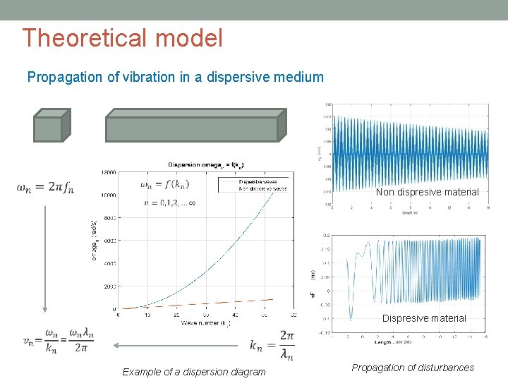
Theoretical model Propagation of vibration in a dispersive medium Non dispresive material Dispresive material Example of a dispersion diagram Propagation of disturbances
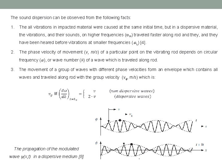
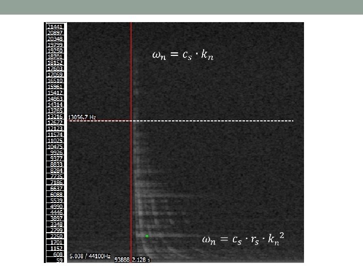
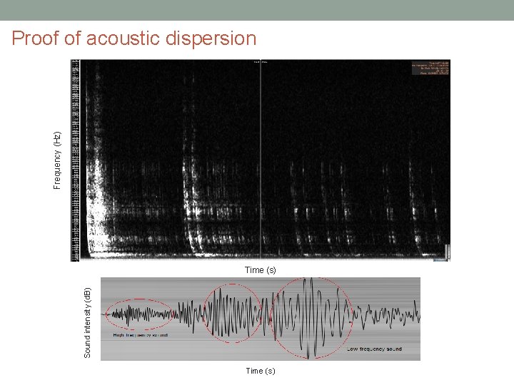
The sound dispersion can be observed from the following facts: 1. The all vibrations in impacted material were caused at the same initial time, but in a dispersive material, the vibrations, and their sounds, on higher frequencies ( H) traveled faster along rod and they, and they have been heared before vibrations at smaller frequencies ( L) [4]. 2. The phase velocity of movement (v, m/s) of a particular point on the vibrating rod depends on circular frequency ( ), or wave number (k) of a wave which is traveled along rod. 3. The movement of a group of waves with different phase velocities form an envelope which contains all waves and traveled along rod with the group velocity (vg, m/s) which is: The propagation of the modulated wave (x, t) in a dispersive medium [8]
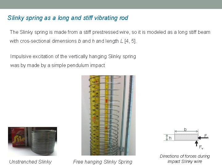
Slinky spring as a long and stiff vibrating rod The Slinky spring is made from a stiff prestressed wire, so it is modeled as a long stiff beam with cros-sectional dimensions b and h and length L [4, 5]. Impulsive excitation of the vertically hanging Slinky spring was by made by a simple pendulum impact b Fh h Fv Unstrenched Slinky Free hanging Slinky Spring Directions of forces during impact Slinky wire
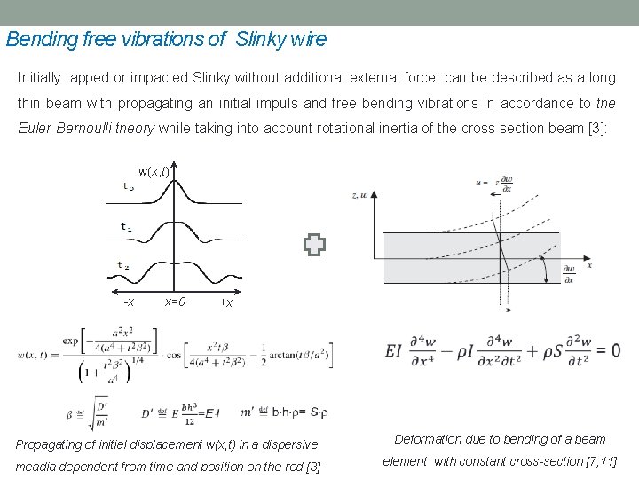
Bending free vibrations of Slinky wire Initially tapped or impacted Slinky without additional external force, can be described as a long thin beam with propagating an initial impuls and free bending vibrations in accordance to the Euler-Bernoulli theory while taking into account rotational inertia of the cross-section beam [3]: w(x, t) -x x=0 +x Propagating of initial displacement w(x, t) in a dispersive Deformation due to bending of a beam meadia dependent from time and position on the rod [3] element with constant cross-section [7, 11]
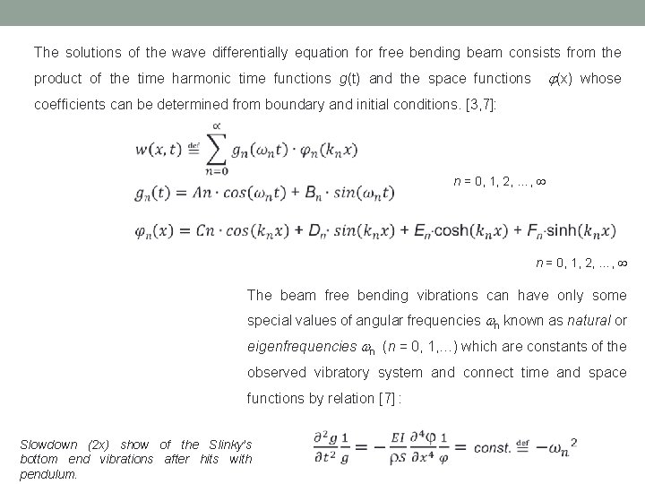
The solutions of the wave differentially equation for free bending beam consists from the product of the time harmonic time functions g(t) and the space functions (x) whose coefficients can be determined from boundary and initial conditions. [3, 7]: n = 0, 1, 2, …, The beam free bending vibrations can have only some special values of angular frequencies n known as natural or eigenfrequencies n (n = 0, 1, …) which are constants of the observed vibratory system and connect time and space functions by relation [7] : Slowdown (2 x) show of the Slinky’s bottom end vibrations after hits with pendulum.
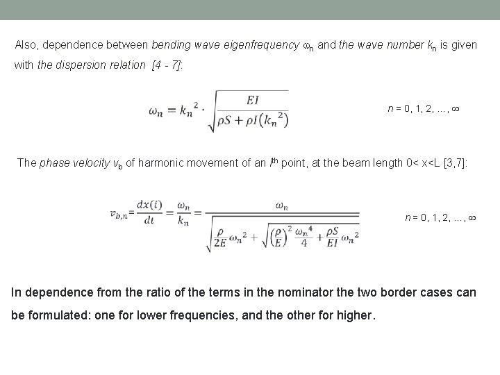
Also, dependence between bending wave eigenfrequency n and the wave number kn is given with the dispersion relation [4 - 7]: n = 0, 1, 2, …, The phase velocity vb of harmonic movement of an ith point, at the beam length 0< x<L [3, 7]: n = 0, 1, 2, …, In dependence from the ratio of the terms in the nominator the two border cases can be formulated: one for lower frequencies, and the other for higher.
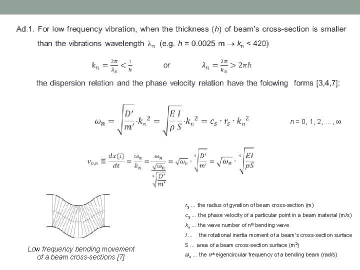
n = 0, 1, 2, …, r. S … the radius of gyration of beam cross-section (m) c. S … the phase velocity of a particular point in a beam material (m/s) kn … the wave number of nth bending wave I … the rotational inertia moment of a beam’s cross-section surface Low frequency bending movement of a beam cross-sections [7] S … area of a beam cross-section surface (m 2) n … the nth eigencircular frequency of a bending beam (rad/s)
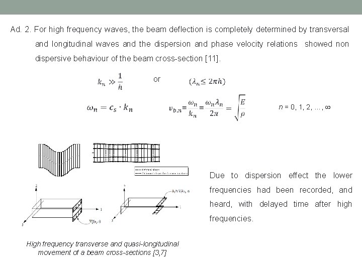
Ad. 2. For high frequency waves, the beam deflection is completely determined by transversal and longitudinal waves and the dispersion and phase velocity relations showed non dispersive behaviour of the beam cross-section [11]. or n = 0, 1, 2, …, Due to dispersion effect the lower frequencies had been recorded, and heard, with delayed time after high frequencies. High frequency transverse and quasi-longitudinal movement of a beam cross-sections [3, 7]
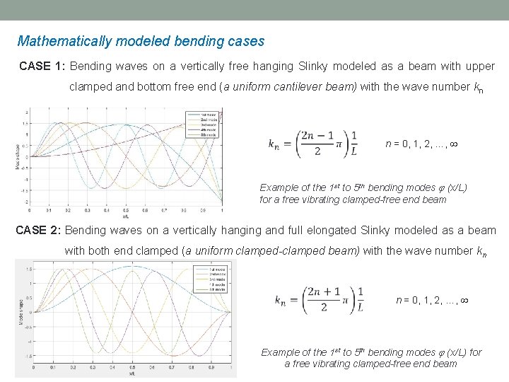
Mathematically modeled bending cases CASE 1: Bending waves on a vertically free hanging Slinky modeled as a beam with upper clamped and bottom free end (a uniform cantilever beam) with the wave number kn n = 0, 1, 2, …, Example of the 1 st to 5 th bending modes (x/L) for a free vibrating clamped-free end beam CASE 2: Bending waves on a vertically hanging and full elongated Slinky modeled as a beam with both end clamped (a uniform clamped-clamped beam) with the wave number kn n = 0, 1, 2, …, Example of the 1 st to 5 th bending modes (x/L) for a free vibrating clamped-free end beam
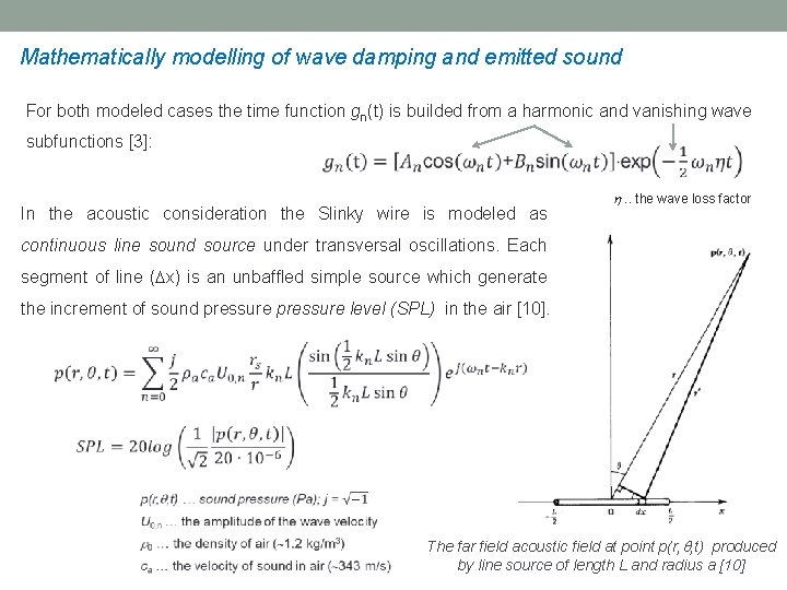
Mathematically modelling of wave damping and emitted sound For both modeled cases the time function gn(t) is builded from a harmonic and vanishing wave subfunctions [3]: In the acoustic consideration the Slinky wire is modeled as . . the wave loss factor continuous line sound source under transversal oscillations. Each segment of line ( x) is an unbaffled simple source which generate the increment of sound pressure level (SPL) in the air [10]. The far field acoustic field at point p(r, , t) produced by line source of length L and radius a [10]
Table of contents I • Problem description II • Theoretical model III • Experimental measurements IV • Analysis of experimental results V • Conclusions
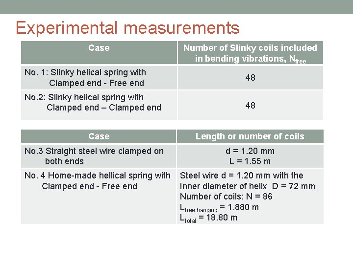
Experimental measurements Case Number of Slinky coils included in bending vibrations, Nfree No. 1: Slinky helical spring with Clamped end - Free end 48 No. 2: Slinky helical spring with Clamped end – Clamped end 48 Case No. 3 Straight steel wire clamped on both ends Length or number of coils d = 1. 20 mm L = 1. 55 m No. 4 Home-made hellical spring with Steel wire d = 1. 20 mm with the Clamped end - Free end Inner diameter of helix D = 72 mm Number of coils: N = 86 Lfree hanging = 1. 880 m Ltotal = 18. 80 m
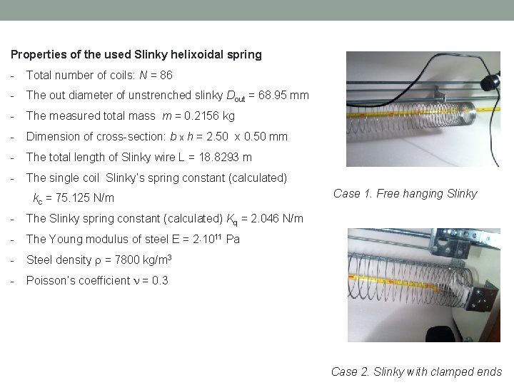
Properties of the used Slinky helixoidal spring - Total number of coils: N = 86 - The out diameter of unstrenched slinky Dout = 68. 95 mm - The measured total mass m = 0. 2156 kg - Dimension of cross-section: b x h = 2. 50 x 0. 50 mm - The total length of Slinky wire L = 18. 8293 m - The single coil Slinky’s spring constant (calculated) kc = 75. 125 N/m - The Slinky spring constant (calculated) Kq = 2. 046 N/m - The Young modulus of steel E = 2 1011 Pa - Steel density = 7800 kg/m 3 - Poisson’s coefficient = 0. 3 Case 1. Free hanging Slinky Case 2. Slinky with clamped ends
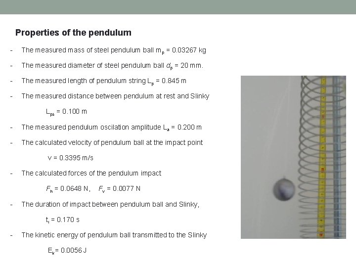
Properties of the pendulum - The measured mass of steel pendulum ball mp = 0. 03267 kg - The measured diameter of steel pendulum ball dp = 20 mm. - The measured length of pendulum string Lp = 0. 845 m - The measured distance between pendulum at rest and Slinky Lps = 0. 100 m - The measured pendulum oscilation amplitude La = 0. 200 m - The calculated velocity of pendulum ball at the impact point v = 0. 3395 m/s - The calculated forces of the pendulum impact Fh = 0. 0648 N, Fv = 0. 0077 N - The duration of impact between pendulum ball and Slinky, ti = 0. 170 s - The kinetic energy of pendulum ball transmitted to the Slinky Ek= 0. 0056 J
Table of contents I • Problem description II • Theoretical model III • Experimental measurements IV • Analysis of experimental results V • Conclusions
Frequency (Hz) Proof of acoustic dispersion Sound intensity (d. B) Time (s)
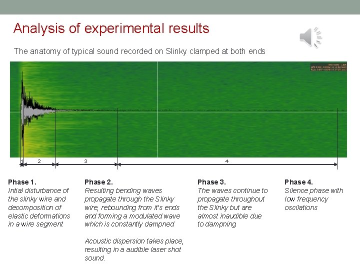
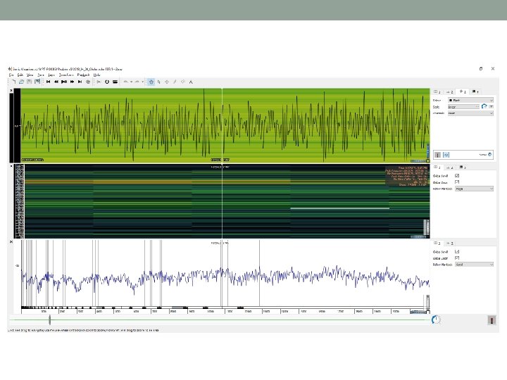
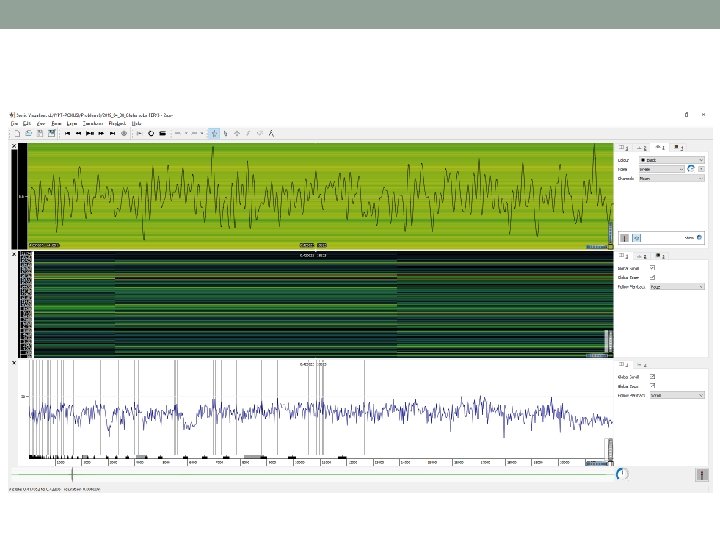
Analysis of experimental results The anatomy of typical sound recorded on Slinky clamped at both ends 1 2 Phase 1. Intial disturbance of the slinky wire and decomposition of elastic deformations in a wire segment 3 Phase 2. Resulting bending waves propagate through the Slinky wire, rebounding from it’s ends and forming a modulated wave which is constantly dampned Acoustic dispersion takes place, resulting in a audible laser shot sound. 4 Phase 3. The waves continue to propagate throughout the Slinky but are almost inaudible due to dampning Phase 4. Silence phase with low frequency oscilations
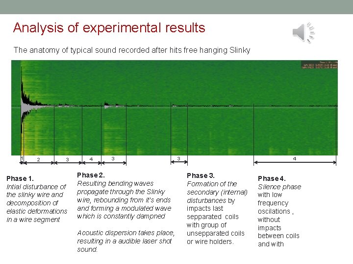
Analysis of experimental results The anatomy of typical sound recorded after hits free hanging Slinky 1 2 3 Phase 1. Intial disturbance of the slinky wire and decomposition of elastic deformations in a wire segment 4 3 Phase 2. Resulting bending waves propagate through the Slinky wire, rebounding from it’s ends and forming a modulated wave which is constantly dampned Acoustic dispersion takes place, resulting in a audible laser shot sound. 3 4 Phase 3. Formation of the secondary (internal) disturbances by impacts last sepparated coils with group of unsepparated coils or wire holders. Phase 4. Silence phase with low frequency oscilations , without impacts between coils and with
Frequency (Hz) Time delay between higher and lower frequencies Time (s)
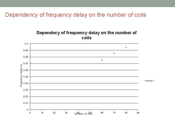
Dependency of frequency delay on the number of coils Dependecy of frequency delay on the number of coils 0. 1 0. 09 Frequency delay (s) 0. 08 0. 07 0. 06 0. 05 Series 1 0. 04 0. 03 0. 02 0. 01 0 0 10 20 30 40 50 Number of coils 60 70 80 90
Table of contents I • Problem description II • Theoretical model III • Experimental measurements IV • Analysis of experimental results V • Conclusions
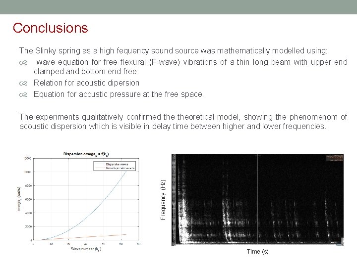
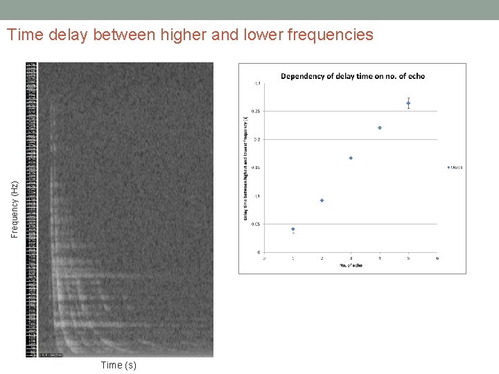
Conclusions The Slinky spring as a high fequency sound source was mathematically modelled using: wave equation for free flexural (F-wave) vibrations of a thin long beam with upper end clamped and bottom end free Relation for acoustic dipersion Equation for acoustic pressure at the free space. Frequency (Hz) The experiments qualitatively confirmed theoretical model, showing the phenom of acoustic dispersion which is visible in delay time between higher and lower frequencies. Time (s)
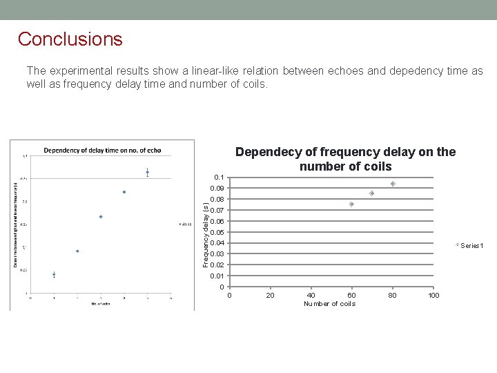
Conclusions The experimental results show a linear-like relation between echoes and depedency time as well as frequency delay time and number of coils. Dependecy of frequency delay on the number of coils 0. 1 Frequency delay (s) 0. 09 0. 08 0. 07 0. 06 0. 05 0. 04 Series 1 0. 03 0. 02 0. 01 0 0 20 40 60 Number of coils 80 100
REFERENCES [1] P. Gash: Fundamental Slinky Oscillation Frequency using a Center-of-Mass Model [2] V. Henč-Bartolić, P. Kulušić: Waves and optics, School book, Zagreb, 3 rd edition (in Croatian), 2004 [3] A. Nilsson, B. Liu: Vibro-Acoustics, Vol. 1, Springer-Verlag Gmb. H, Berlin Heidelberg, 2015 [4] F. S. Crafword: Slinky whistlers, Am. J. Phys. 55(2), February 1987, p. 130 -134 [5] F. S. Crafword: Waves, Berkeley Physics Course, Vol. 3, Berkely, 1968 [6] W. C. Elmore, M. A. Heald: Physics of waves, Mc. Graw-Hill Book Company, New York, [7] J. G. Guyader: Vibration in continuous media, ISTE Ltd, London, 2002 [8] G. C. King: Vibrations and waves, John Wiley & Sons Ltd, London, 2009 [9] Th. D. Rossing, N. H. , Fletcher: Principles of vibration and sounds, Springer-Verlag. New York, lnc. , 2004 [10] L. E. Kinsle et. all: Fundamentals of Acoustics, 4 th ed. , John Willey & Sons, Inc, New York, 2000 [11] M. Géradin, D. J. Rixen: Mechanical Vibrations: Theory and Application to Structural Dynamics, 3 rd ed. , John Wiley & Sons, Ltd, Chichester, 2015 [12] C. Y. Wang , C. M. Wang: Structural Vibration - Exact Solutions for. Strings, Membranes, Beams, and Plates, CRC Press. Taylor & Francis Group, Boca Raton, 2014 [13] A. Brandt: Noise and vibration analysis : signal analysis and experimental procedures, John Wiley & Sons Ltd, Chichester, 2011

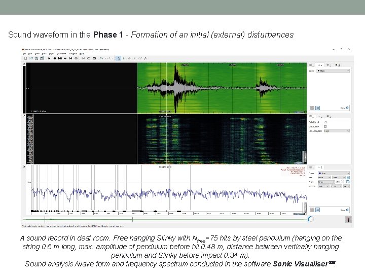
Sound waveform in the Phase 1 - Formation of an initial (external) disturbances A sound record in deaf room. Free hanging Slinky with Nfree=75 hits by steel pendulum (hanging on the string 0. 6 m long, max. amplitude of pendulum before hit 0. 48 m, distance between vertically hanging pendulum and Slinky before impact 0. 34 m). Sound analysis /wave form and frequency spectrum conducted in the software Sonic Visualiser.
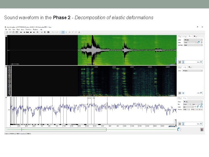
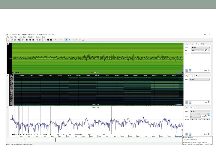
Sound waveform in the Phase 2 - Decomposition of elastic deformations
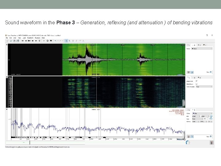
Sound waveform in the Phase 3 – Generation, reflexing (and attenuation ) of bending vibrations
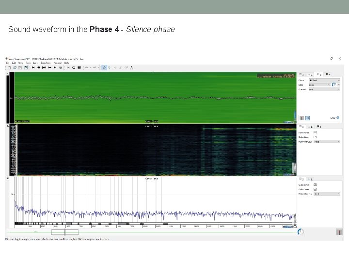
Sound waveform in the Phase 4 - Silence phase
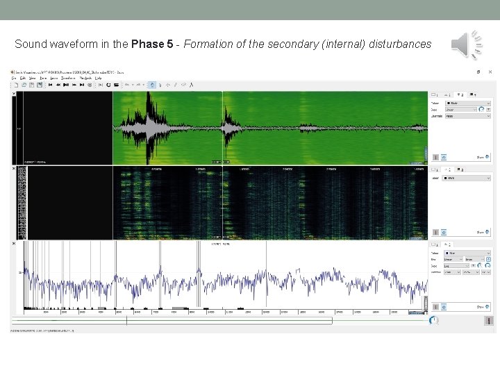
Sound waveform in the Phase 5 - Formation of the secondary (internal) disturbances
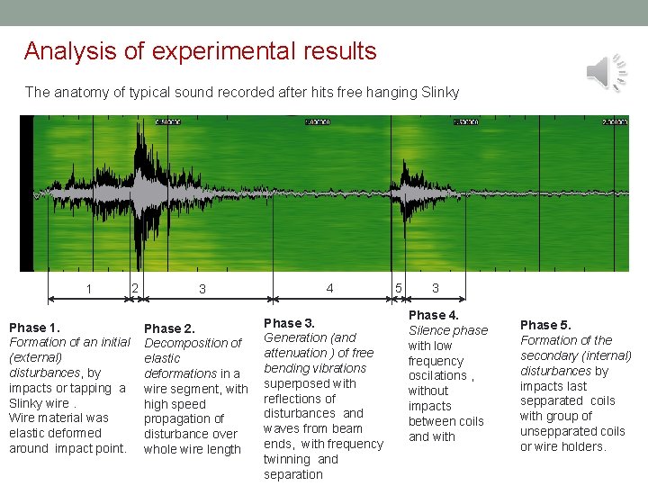
Analysis of experimental results The anatomy of typical sound recorded after hits free hanging Slinky 1 Phase 1. Formation of an initial (external) disturbances, by impacts or tapping a Slinky wire. Wire material was elastic deformed around impact point. 2 3 4 Phase 3. Phase 2. Generation (and Decomposition of attenuation ) of free elastic bending vibrations deformations in a wire segment, with superposed with reflections of high speed disturbances and propagation of waves from beam disturbance over ends, with frequency whole wire length twinning and separation 5 3 Phase 4. Silence phase with low frequency oscilations , without impacts between coils and with Phase 5. Formation of the secondary (internal) disturbances by impacts last sepparated coils with group of unsepparated coils or wire holders.
- Slides: 41