Principles of design of the tooth borne RPD

Principles of design of the tooth borne RPD Dr. Nesreen Salim

RPD CLASSIFICATION �The common classification system used in the UK for partial dentures is that devised by Kennedy. This Classification is based on the frequency of the partially edentulous state. It is descriptive of the anatomical form of the respective arch and merely provides an overall description of where the saddles are without outlining the size of the saddles. �The classification advocated by Beckett outlines the source/s of support.
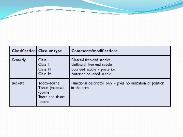
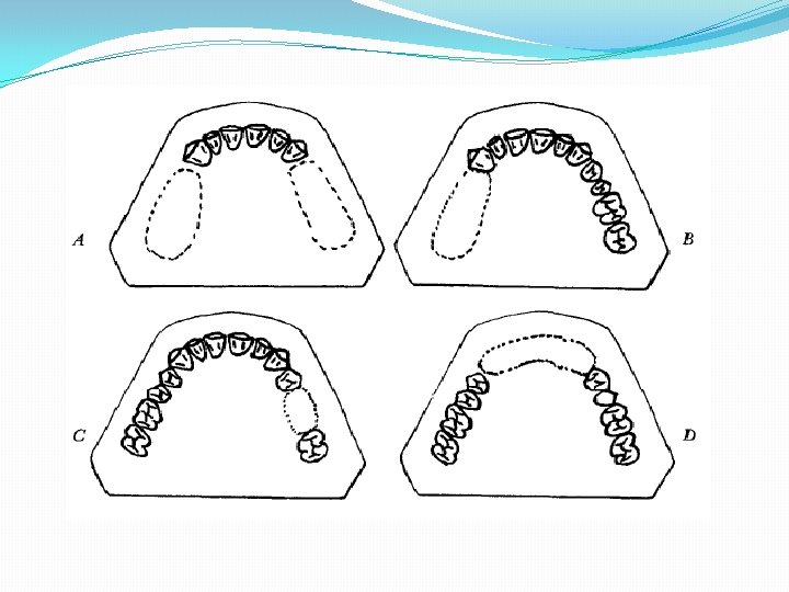

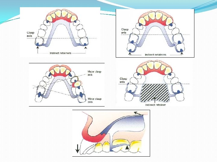
DIFFERENTIATION BETWEEN TWO MAIN TYPES OF REMOVABLE PARTIAL DENTURES �The Class I and Class II tissues underlying the base and only limited support from the abutment teeth. Class III abutment teeth at each end of the edentulous space �Impression tech. �Need for indirect retainers. �Need for relining in future.

Components of RPD �Supporting Elements These may be rests on the crowns of teeth, coronal restorations, root faces of teeth, mucosa or implants. �Retaining Elements These are termed direct retainers and may be clasps, precision retainers, guiding plates acting on surfaces. �Connecting Elements These may be major connectors, which join up the saddles, or minor connectors that join rests or direct retainers to the major connector. �Anti-rotational Components Often referred to as indirect retainers, although they also function as supporting elements for the framework. �Denture Base Material and Flange The denture base material and denture flange may serve as one or more of the above components.

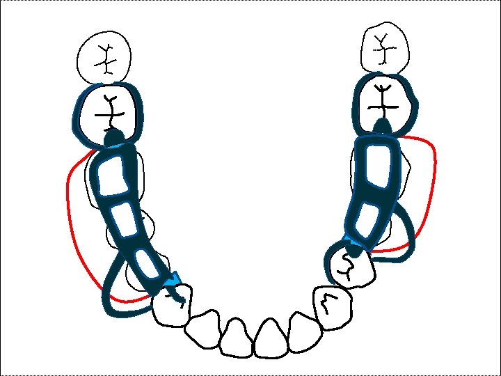
Principles of design 1. Outline the saddles and determine which ones need to be restored. 2. Decide on the nature of the support. 3. Decide on how best to maximize retention. 4. Decide on how best to unite the saddles. 5. Decide whether anti-rotational devices are required and, if so, how this is achieved. 6. Re-assess for hygiene and, with an eye on the future, maintenance of the prosthesis (e. g. relining, repair and replacement of components of precision attachments) and the prognosis of the remaining dentition. 7. Decide on how the occlusion is to be planned and, at the same time, plan with appearance in mind.

Simply: 1. Saddles. 2. Support. 3. Retention. 4. Bracing and reciprocation. 5. Connector. 6. Indirect retention. 7. Review of completed design.

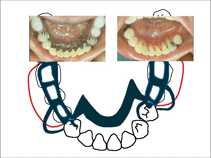
Design of tooth borne RPD �Draw the design on the study cast/s as well as on the prescription form. � The study casts should be articulated and the occlusion examined to confirm the clinical examination and identify any problems this may pose for the construction of the RPD (e. g. space for components of the RPD such as occlusal rests)

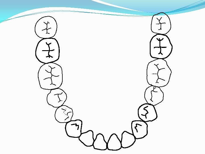
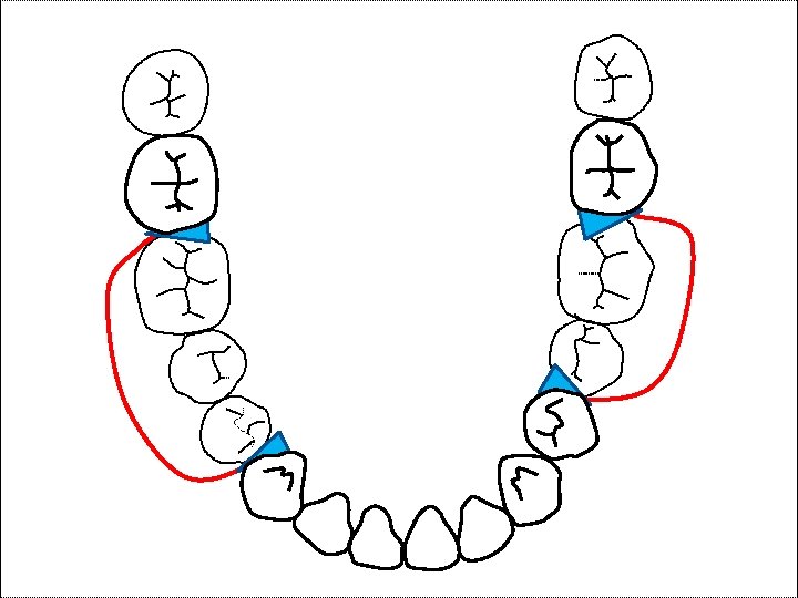
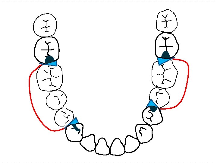
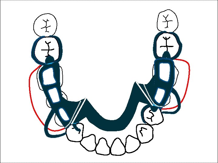
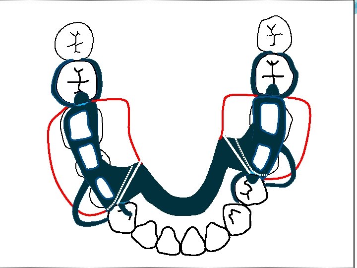
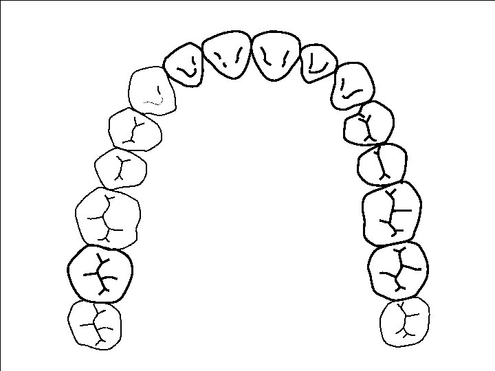
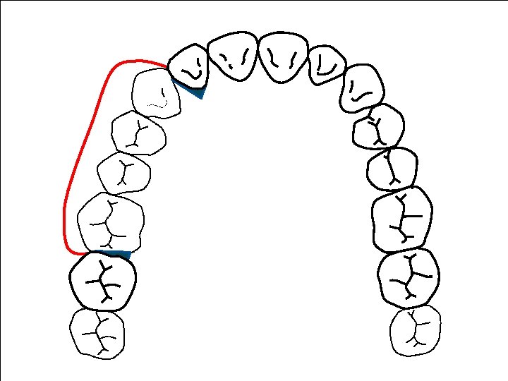
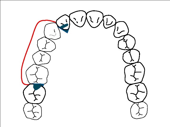
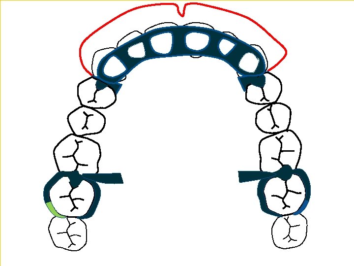
�It is necessary at this stage to make use of the surveyor and mark the path of insertion of the denture, undercuts on the teeth, depth of any undercuts, and the presence of unwanted undercuts, which will need to be blocked out. �Outlining the saddles: determine the places where it is intended to place RPD saddle areas

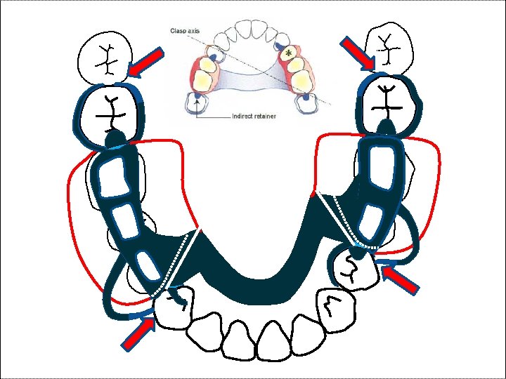
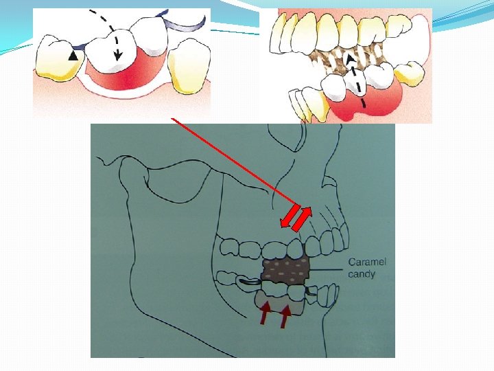
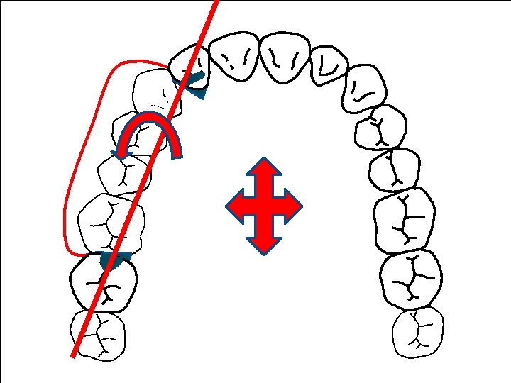
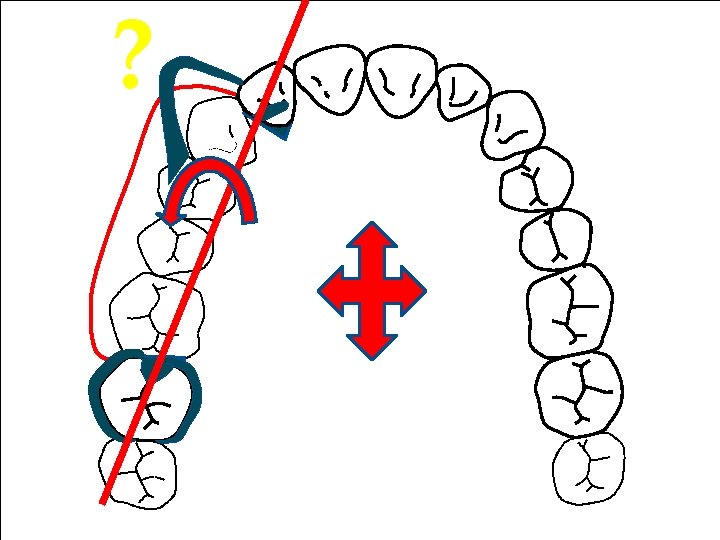
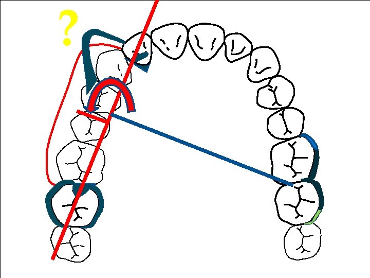
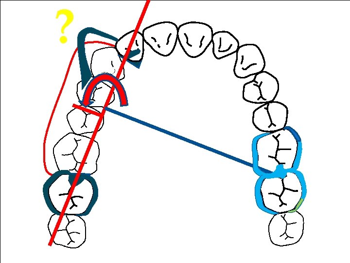
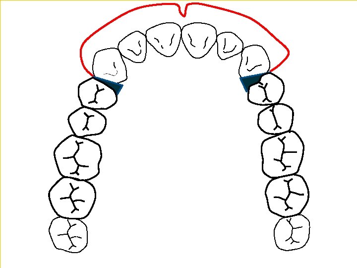
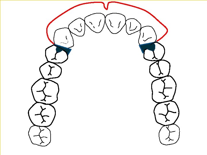
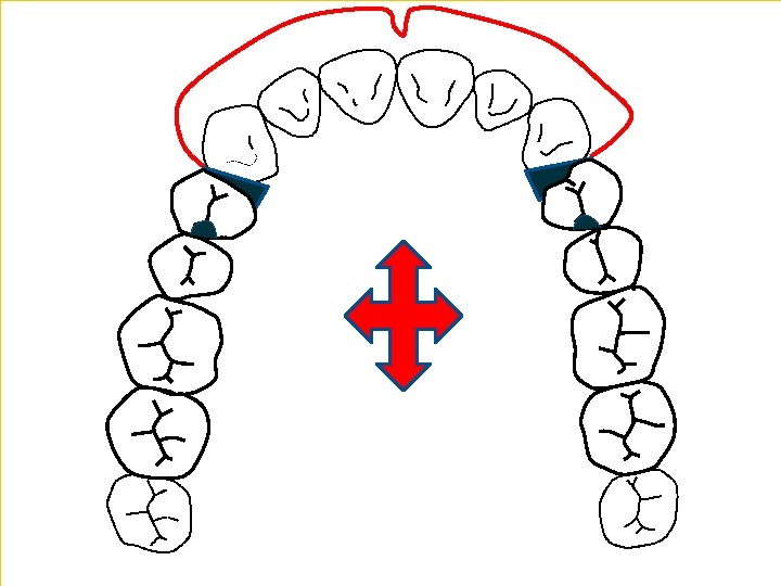
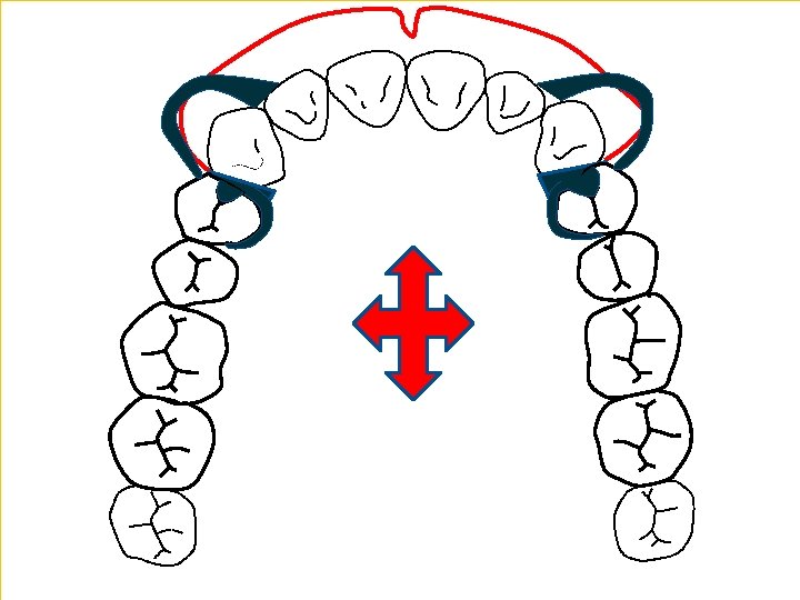
The principle of tilting the cast to enhance retention is that by so altering the path of insertion (1) a rigid part of the denture can enter an area of the tooth surface or an area of the ridge which is undercut relative to the path of displacement (2). In this example, providing retention by engaging the distal undercut (*) of the canine may well look more pleasing than a clasp arm on the same tooth.

�Outlining Support: Rest seats, preparation is a prerequisite 1 - to direct forces down the long axes of the teeth, because these are the forces teeth can withstand much better than lateral or ‘jiggling’ forces. 2 - definite seat ensures there are no sharp edges to irritate the tongue. 3 - Rests also act as indirect retainers for Kennedy Class I and Class IV partial dentures.

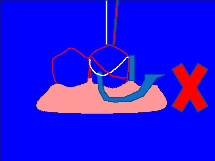
�A guide surface* allows a reciprocating component to maintain continuous contact with a tooth as the denture is displaced occlusally. The retentive arm of the clasp is thus forced to flex as it moves up the tooth. It is this elastic deformation of the clasp that creates the retentive force. �Guide surfaces ensure that the patient removes the denture along a planned path (1). The clasps are therefore flexed to the extent for which they were designed. Without guide surfaces the patient may tilt or rotate the denture on removal (2), causing clasps to flex beyond their proportional limit.

� The reciprocal element which is in contact with the side of the tooth opposite the retentive clasp can also play an important role in the effectiveness of the latter, and thus in the overall retention of the denture. (1) A horizontally directed force is produced as a retentive arm is displaced in an occlusal direction over the bulbosity of a tooth. If the clasp arm is unopposed the tooth is displaced in the periodontal space and much of the retentive capability will be lost. (2) If the retentive clasp is opposed by a rigid component which maintains contact with the tooth as the retentive arm moves over the bulbosity of the tooth, displacement of the tooth is resisted, the retentive arm is forced to flex and thus the efficiency of the retentive element is increased. This principle is known as reciprocation. It is thus apparent that reciprocation is required as the denture is being displaced occlusally whilst the bracing function, as mentioned earlier, comes into play when the denture is fully seated.
 A clasp is effective in retention from its position when the denture")
� 1) A clasp is effective in retention from its position when the denture is fully seated to where it escapes over the bulbosity of the tooth. This vertical measurement may be termed the 'retention distance'. It will be appreciated that the reciprocal element on the other side of the tooth should be in continuous contact with the tooth surface as the retentive arm traverses the 'retention distance'. Effective reciprocation can be achieved either (2) by a clasp arm contacting a guide surface of similar height to the 'retention distance', or (3) by a plate making continuous contact with the tooth surface as the retentive arm moves through its 'retention distance'. (4) If the reciprocating clasp is placed on a tooth without an adequate guide surface, it will lose contact with the tooth before the retentive arm has passed over the maximum bulbosity of the tooth and fail to provide effective reciprocation.

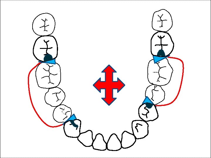
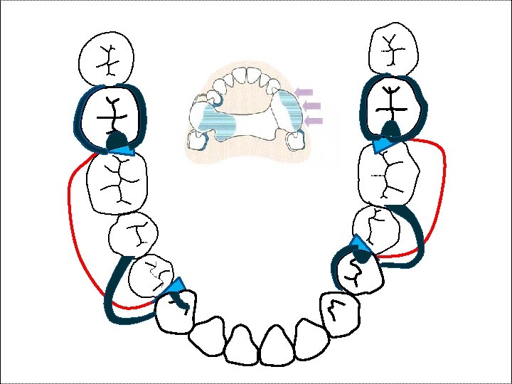
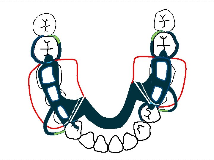
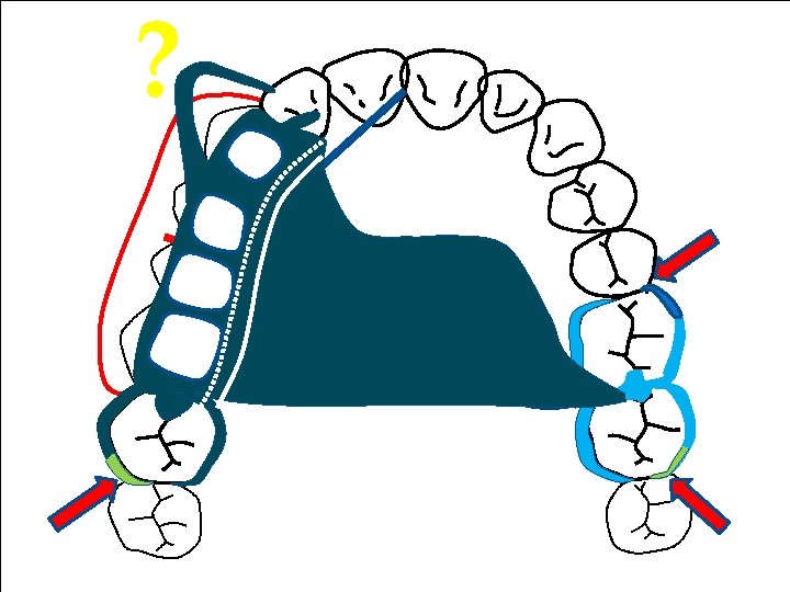
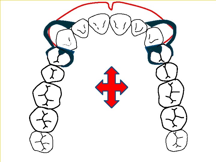
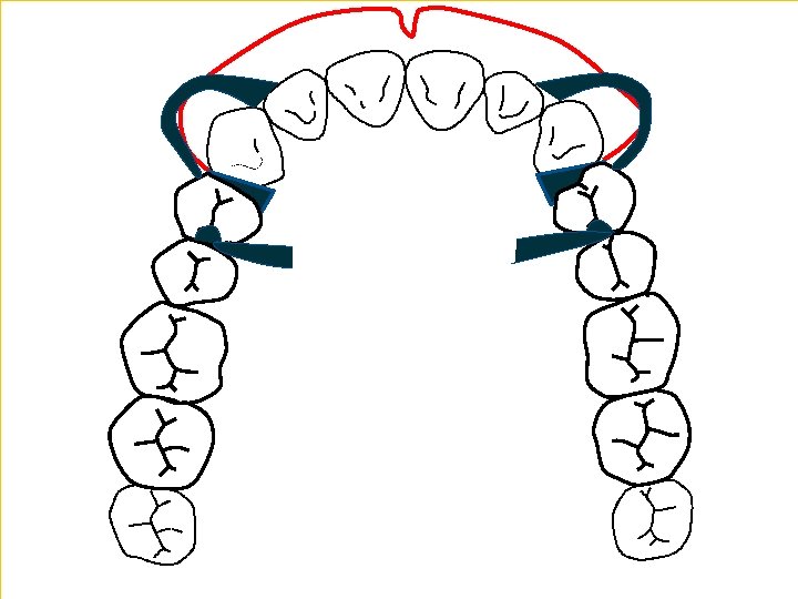
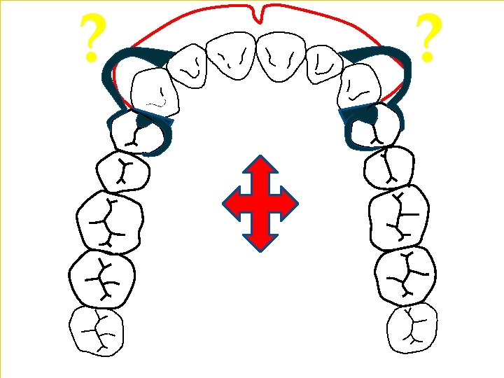
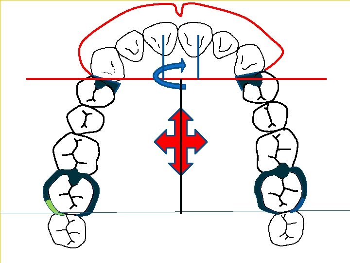
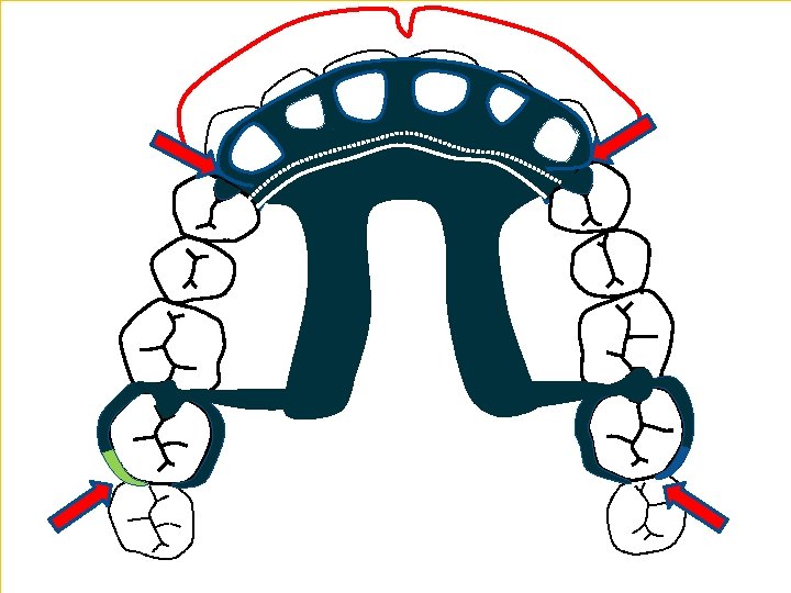
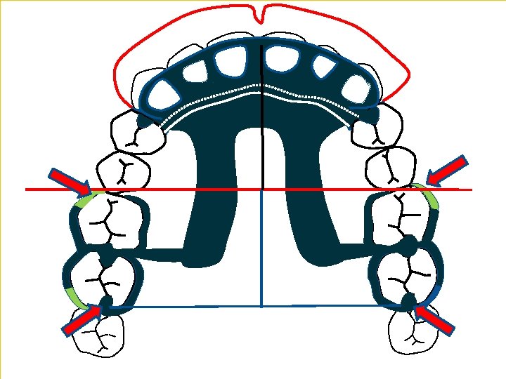
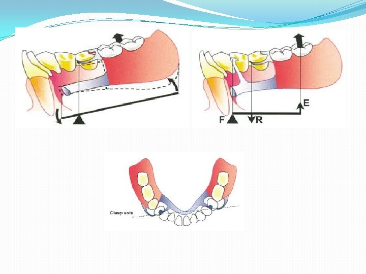
Bracing �The horizontal forces are resisted by placing rigid components of the denture (bracing components) against suitable vertical surfaces on the teeth and residual ridges. Parts of a denture resting against the stippled areas will resist the forces whose directions are shown by the arrows. It is important to appreciate that bracing occurs only when the denture is fully seated.
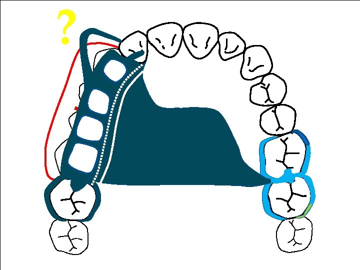
: provides excellent attachment of acrylic resin bases, minimizes warping of")
�Ladder-like minor connector (open): provides excellent attachment of acrylic resin bases, minimizes warping of bases resulting from the release of inherent strains in compression-molded acrylic resin. �Mesh pattern minor connectors: to attach acrylic resin denture bases to the framework. rigid and possessing adequate strength, bulk of connector itself may contribute to weakening of acrylic resin base.
, horseshoe. �The ring")
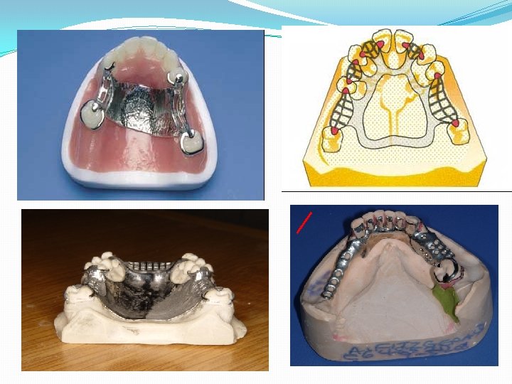
�Selecting the Major Connector Maxilla: plate, strap, ring (anterior-posterior palatal strap), horseshoe. �The ring design, and all bar types of major connector, tends to have a number of edges noticeable to the tongue, and are thicker although they cover less tissue. Plate designs tend to be thinner and less noticeable, but do cover a wider area of the palate. �Where there is a torus, or the patient wishes to avoid too much palatal coverage, a horseshoe design or ring design is indicated.

�Mandible: 1 - The lingual bar +ve hygienic since it does not cover the teeth but a depth of functional lingual sulcus of at least 8 mm is required to combine stability of the denture with health to the remaining dentition, -ve considered to be more noticeable to the tongue, and cannot act, on its own, as an indirect retainer with distal extension cases. 2 -The lingual plate +ve more acceptable to the tongue, can act as an indirect retainer, -ve it does of course cover the lingual surfaces of the lower anterior teeth, thus predisposing to caries and gingival/periodontal irritation. The appearance may also be poor if there is spacing between the teeth. 3 -The sublingual bar which fits in the lingual pouch beneath the tongue and is +ve less noticeable, more rigid. –ve more bulky than a lingual bar (it is half pear-shaped and requires a 10 mm space from lingual gingival margins to the lingual reflection), careful attention must be paid to the impression technique, using functional tongue movements to roll the impression material while it is setting.

4 -The dental bar may be used where there is a limited lingual sulcus, but as this fits onto the cingulum region of the teeth and has to be -ve bulky for strength, it may not be readily acceptable to the patient. 5 -The labial or buccal bar is recommended for lingually inclined lower anterior teeth such as Skeletal III cases. 6 - The Kennedy bar is a combination of a continuous clasp on the lingual surfaces of the lower anterior teeth and a lingual bar. This type of major connector tends not to be well perceived by patients owing to the number of edges that are in contact with the tongue
 is based on")
� Selection of connector type. Selection of the type of connector(s) is based on four factors: mouth comfort, rigidity, location of denture bases, and indirect retention.

�Tooth shape influences retention by determining the depth and steepness of undercut available for clasping. Clasps 1 and 2 are positioned in the same amount of undercut and therefore provide the same overall retentive force. However, for the same small vertical displacement, clasp 1 is deflected more than clasp 2 and therefore offers greater initial resistance to the displacing forces. undercut area nearer to the saddle: ring clasp Tilted molar: ring clasp

When guide surfaces are used to provide resistance to displacement of the denture in an occlusal direction, the retentive portion of the clasp needs only to resist movement along the path of withdrawal and therefore can be positioned solely with reference to the red survey line.

A gingivally approaching clasp positioned at the cross-over point of the survey lines resists movement along both the path of withdrawal and the path of displacement without being permanently deformed by movement along either path.

M D

1 -Maximum contact of proximal plate minor connector with guiding plane produces more horizontal distribution of stress. 2 - Minimum contact or disengagement of minor connector with guiding plane allows rotation around fulcrum located on mesio-occ 1 usal rest, producing more vertical distribution of stress to ridge area. 3 - Minor connector contact with guiding plane from marginal ridge to junction of middle and gingival thirds of abutment tooth distributes load vertically to ridge and horizontally to abutment tooth.
- Slides: 66