Principle Of Centrifugal Pump Operation Subject Pump Piping
")
Principle Of Centrifugal Pump Operation Subject: Pump & Piping System (FCB 30302)

Introduction A centrifugal pump is a machine. It is a machine that imparts energy to a fluid. This energy infusion cause a liquid to flow, rise to a higher level, or both. The centrifugal pump is a member of a family known as rotary Machines and consists of two basic parts. 1) The rotary element or impeller and 2) The stationary element or casing (volute).

The History The centrifugal pump was developed in Europe in the late 1600’s and was seen in the United States in the early 1800’s. Prior to that time, the vast majority of pumping applications involved positive displacement pumps. The increased popularity of centrifugal pumps is due largely to the comparatively recent development of high speed electric motors, steam turbines, and internal combustion engines. The centrifugal pump is a relatively high speed machine and the development of high speed drivers has made possible the development of compact, efficient pumps.

Since the 1940's, the centrifugal pump has become the pump of choice for many applications. Research and development has resulted in both improved performance and new materials of construction that have greatly expanded it's field of applicability. Modern centrifugal pumps have been built to meet conditions far beyond what was thought possible fifty to sixty years ago. Pumps capable of delivering over 1, 000 gallons per minute at heads of more than 300 feet are common in the nuclear power industry. And, boiler feed pumps have been developed that deliver 300 gallons per minute at more than 1800 feet of head.

Flexible Impeller Common pumping principles Progressing cavity Rotary Peristaltic Positive displacement Vane Roller Gear Lobe Diaphragm Pump Reciprocating Plunger Piston Centrifugal Kinetic Turbine Screw

Working Mechanism of a Centrifugal Pump A centrifugal pump purposes is to convert energy of a prime mover (a electric motor or turbine) first into velocity or kinetic energy and then into pressure energy of a fluid that is being pumped. The energy changes occur by virtue of two main parts of the pump, the impeller and the volute or diffuser. The impeller is the rotating part that converts driver energy into the kinetic energy. The volute or diffuser is the stationary part that converts the kinetic energy into pressure energy
 of a")
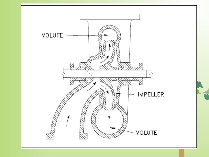
The process liquid enters the suction nozzle and then into eye (center) of a revolving device known as an impeller. When the impeller rotates, it spins the liquid sitting in the cavities between the vanes outward and provides centrifugal acceleration. As liquid leaves the eye of the impeller a low-pressure area is created causing more liquid to flow toward the inlet. Because the impeller blades are curved, the fluid is pushed in a tangential and radial direction by the centrifugal force. This force acting inside the pump is the same one that keeps water inside a bucket that is rotating at the end of a string.

Figure below depicts a side cross-section of a centrifugal pump indicating the movement of the liquid.
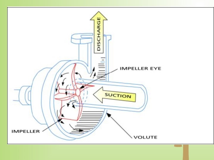

Conversion of Kinetic Energy to Pressure Energy • The key idea is that the energy created by the centrifugal force is kinetic energy. • The amount of energy given to the liquid is proportional to the velocity at the edge or vane tip of the impeller. • The faster the impeller revolves or the bigger the impeller is, then the higher will be the velocity of the liquid at the vane tip & the greater the energy imparted to the liquid. • This kinetic energy of a liquid coming out of an impeller is harnessed by creating a resistance to the flow. • The first resistance is created by the pump volute (casing) that catches the liquid and slows it down. • In the discharge nozzle, the liquid further decelerates & its velocity is converted to pressure according to Bernoulli’s principle.

General Components of Centrifugal Pumps A centrifugal pump has two mains component: i. A rotating component comprised of an impeller and a shaft ii. A stationary component comprised of a casing, casing cover, and bearings.


Stationary components Casing • Casings are generally of two types: i. Volute ii. Circular 1. Volute casings build a higher head; circular casings are used for low head and high capacity. • A volute is a curved funnel increasing in area to the discharge port. • As the area of the cross-section increases, the volute reduces the speed of the liquid and increases the pressure of the liquid.

Cut-away of a pump showing volute casing

• One of the main purposes of a volute casing is to help balance the hydraulic pressure on the shaft of the pump. • Running volute-style pumps at a lower capacity than the manufacturer recommends can put lateral stress on the shaft of the pump, increasing wear-and-tear on the seals and bearings, and on the shaft itself. • Centrifugal pumps can also be constructed in a manner that results in two distinct volutes, each receiving the liquid that is discharged from a 180° region of the impeller at any given time.

• Double-volute casings are used when the radial thrusts become significant at reduced capacities. • Pumps of this type are called double volute pumps (they may also be referred to a split volute pumps). • In some applications the double volute minimizes radial forces imparted to the shaft and bearings due to imbalances in the pressure around the impeller. • A comparison of single and double volute centrifugal pumps is shown in the figure.

Single and double volute

Location volute in centrifugal pump

• Circular casing have stationary diffusion vanes surrounding the impeller periphery that convert velocity energy to pressure energy. Conventionally, the diffusers are applied to multi-stage pumps. • The casings can be designed either as solid casings or split casings. • Solid casing implies a design in which the entire casing including the discharge nozzle is all contained in one casting or fabricated piece.

• A split casing implies two or more parts are fastened together. When the casing parts are divided by horizontal plane, the casing is described as horizontally split or axially split casing. • When the split is in a vertical plane perpendicular to the rotation axis, the casing is described as vertically split or radially split casing. Casing Wear rings act as the seal between the casing and the impeller.

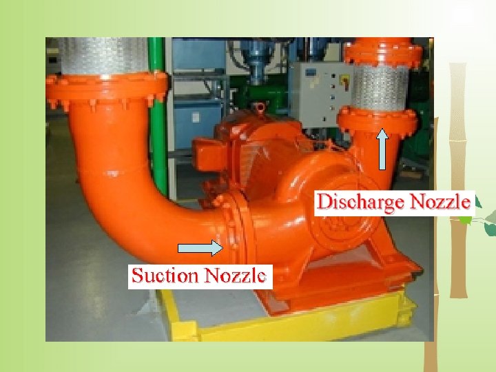
Suction and Discharge Nozzle • The suction and discharge nozzles are part of the casings itself. They commonly have the following configurations. i. iii. End suction/Top discharge Top suction /Top discharge nozzle Side suction / Side discharge nozzles

1. End suction/Top discharge Figure • The suction nozzle is located at the end of, and concentric to, the shaft while the discharge nozzle is located at the top of the case perpendicular to the shaft. • This pump is always of an overhung type and typically has lower NPSHr because the liquid feeds directly into the impeller eye.

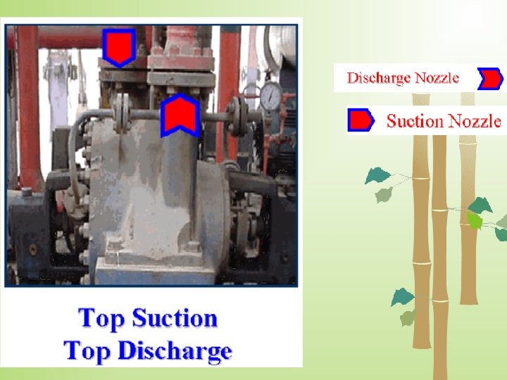
Top suction Top discharge nozzle • The suction and discharge nozzles are located at the top of the case perpendicular to the shaft. • This pump can either be an overhung type or between-bearing type but is always a radially split case pump.

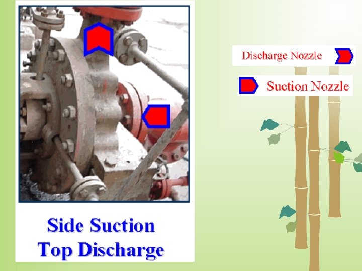
• Side suction / Side discharge nozzles • The suction and discharge nozzles are located at the sides of the case perpendicular to the shaft. • This pump can have either an axially or radially split case type.

Rotating Components Impeller • A centrifugal pump is a machine that transfers mechanical energy from a power unit into pressure and velocity energy in water by the principle of centrifugal force. • In centrifugal pumps, energy is imparted to a fluid by centrifugal action often combined with propeller or lifting action. • Centrifugal pumps can be classified by impeller shape and characteristics. • Impellers are grouped according to the major direction of flow with respect to the axis of rotation. A continuous range in impeller types can be found.

• The most common centrifugal pumps used in irrigation systems are end suction, split case, and the vertical turbine. Suction characteristics of a centrifugal pump is dictated by the design of the eye of the impeller. • Centrifugal pumps are not positive displacement. • The suction fitting is usually one size larger than the discharge fitting. The size of the pump refers to the nominal diameter of the pump discharge fitting. • When the impeller of a centrifugal pump rotates, centrifugal forces develop in the water inside the impeller, which cause water to flow toward the impellers outer edge. • This flow, in turn, results in water flowing into the center or eye of the impeller if the pump is primed. • The output of an impeller depends on the impeller width and on the rate of rotation.

• The pressure developed by the impeller depends on the velocity of the impellers outer edge, which is determined by the impeller diameter and rate of rotation. • At a given rotation rate, the larger the diameter, the greater the pressure, and the greater the width, the higher the flow rate or capacity. • The faster the velocity of the outside rim of the impeller, the greater the energy transferred to the water. • Velocity is increased by increasing rotational speed or the diameter of the impeller.

The impeller is the main rotating part that provides the centrifugal acceleration to the fluid. They are often classified in many ways. Based on major direction of flow in reference to the axis of rotation • Radial flow • Axial flow • Mixed flow

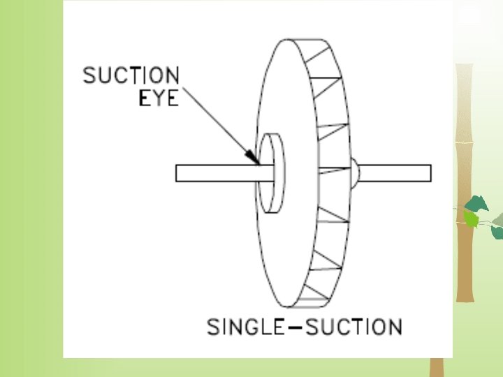
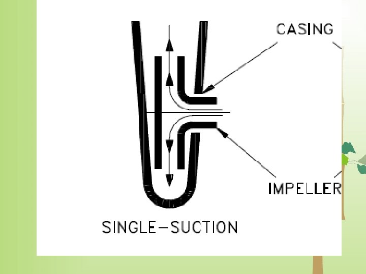
o Based on suction type • Single-suction: Liquid inlet on one side. • Double-suction: Liquid inlet to the impeller symmetrically from both sides. o Based on mechanical construction • Closed: Shrouds or sidewall enclosing the vanes. • Open: No shrouds or wall to enclose the vanes. • Semi-open or vortex type.

Centrifugal Pump Classification by Flow • Centrifugal pumps can be classified based on the manner in which fluid flows through the pump. • The manner in which fluid flows through the pump is determined by the design of the pump casing and the impeller. • The three types of flow through a centrifugal pump are • radial flow, • axial flow • mixed flow.

Impeller Radial Flow Type • Impellers that pump water only through centrifugal force are classified as radial flow because water flows through these impellers in a direction perpendicular to the shaft. It is characteristic of radial flow impellers that the horsepower demand of the impeller increases as the pumping head decreases and flow increases.

• In a radial flow pump, the liquid enters at the center of the impeller and is directed out along the impeller blades in a direction at right angles to the pump shaft. • The impeller of a typical radial flow pump and the flow through a radial flow pump are shown in below figure

Radial type flow

Impeller Axial Flow Type • Pumps with axial flow impellers transfer energy to the water by a lifting force. • Axial flow pumps are sometimes called propeller pumps because they operate essentially the same as the propeller of a boat. • These pumps are not effective in providing pressure for irrigation systems, but are often used as drainage pumps to move large amounts of water at low head (pressure) since they are very effective under those conditions.

• In an axial flow pump, the impeller pushes the liquid in a direction parallel to the pump shaft. • The rotation of an axial flow impeller causes water to flow in a direction parallel to the pump shaft. A characteristic of axial flow impellers is that the horsepower demand decreases as the pumping head decreases • The impeller of a typical axial flow pump and the flow through a radial flow pump are shown in Figure 7.

Axial flow type

Impeller axial flow

Impeller Mixed Flow Type • Mixed flow pumps borrow characteristics from both radial flow and axial flow pumps. • As liquid flows through the impeller of a mixed flow pump, the impeller blades push the liquid out away from the pump shaft and to the pump suction at an angle greater than 90°.

• Mixed flow impellers are often used in irrigation pumping plants, particularly in deep-well turbine pumps. • Mixed flow impellers use both centrifugal and lifting forces. • A characteristic of these pumps is that increasing the flow rate by decreasing the may change the horsepower demand only slightly. • The impeller of a typical mixed flow pump and the flow through a mixed flow pump are shown in figure

Impeller Mixed Flow Type

Impeller Mixed Flow Type

Based on suction type • Impellers of pumps are classified based on the number of points that the liquid can enter the impeller and also on the amount of webbing between the impeller blades. Impellers can be either: • Single suction • Double-suction.

• Single-suction impeller allows liquid to enter the center of the blades from only one direction. • A double-suction impeller allows liquid to enter the center of the impeller blades from both sides simultaneously.
- Slides: 50