Pressurized Mud Cap Drilling for Premier Oil Ardia

 • Equipment •")

 Permits safe and efficient drilling in total loss zones.")


 • The annulus is closed at surface with the")
 100 psi • Permits safe and efficient drilling in")
 –")


- Slides: 32
Pressurized Mud Cap Drilling for Premier Oil Ardia Karnugroho January 9, 2013 © 2013 Weatherford. All rights reserved. 1
Outline • Safety / Drivers • Pressurized Mud Cap Drilling (PMCD) • Equipment • Rig Up • Procedures © 2012 2013 Weatherford. All rights reserved. 2
Safety / Drivers • Optimize drilling process by drilling with a closed-loop drilling system. • Returns-flow-control reduces risk to personnel and the environment from drilling fluids and well control incidents. • To be able to conduct Pressurized Mud Cap Drilling (PMCD) • Basic well control, surface diverter techniques, and other rig equipment remain unchanged. © 2012 2013 Weatherford. All rights reserved. 3
Pressurized Mud Cap Drilling (PMCD) Permits safe and efficient drilling in total loss zones. • No returns to surface (returns flow into the formation) • Viscous fluid is pumped at low rate down the annulus at just below reservoir pressure • Disposable drilling fluid (normally water) is pumped down drillstring • Annular back-pressure is used to balance the reservoir pressure and maintain system balance. © 2012 2013 Weatherford. All rights reserved. 4
Conventional Drilling • Drilling fluid is pumped down the drillstring, and returns to the surface via the annulus • The annulus hydrostatic column is weighted to exceed the reservoir pressure and prevent any flow into the wellbore • Losses are tolerable © 2012 2013 Weatherford. All rights reserved. 5
Drilling with Mud Losses • Drilling fluid is pumped down the drillstring, as further loss zones are uncovered • Increased losses mean little or no mud returns to the surface © 2012 2013 Weatherford. All rights reserved. 6
Drilling with Total Losses • Drilling fluid is pumped down drillstring, but nothing returns to surface. Fluid column drops, reducing BHP, compromising primary well control and leading to a kick. • BOP has to be closed and kick circulated out – but increasing the mud weight leads to more losses and kicks. Ultimately cement may have to be pumped or the well abandoned. © 2012 2013 Weatherford. All rights reserved. 7
Pressurized Mud Cap Drilling (PMCD) • The annulus is closed at surface with the rotating control head. Drillstring injection is switched to sacrificial fluid. • Light annular fluid is pumped down the annulus to maintain hole fill and prevent annular gas migration. • Sacrificial fluid and cuttings are lost to the formation. © 2012 2013 Weatherford. All rights reserved. 8
Pressurized Mud Cap Drilling (PMCD) 100 psi • Permits safe and efficient drilling in severe or total loss zones, while allowing for the detection of influx. • Pore Pressure has to be calculated in order to know the Density of Annular Fluid 200 100 psi RCD Standpipe Pressure Annular Pressure Drilling Mud Water • Injection Test to determine whether that injection will continue once the switch has been made to PMCD • Video © 2012 2013 Weatherford. All rights reserved. 9
Equipment • Equipment Required – Model 7875 Docking Station Rotating Control Devices (RCD) – Valves and Hoses – Riser Crossover – MR-6 C © 2012 2013 Weatherford. All rights reserved. 10
Model 7875 DS RCD • Certified API 16 RCD compliant • 2000 PSI Static Rating • Removable Bearings With Dual Sealing Elements • Hydraulic Latch • Minimum ID: 18. 75” © 2012 2013 Weatherford. All rights reserved. 11
Model 7875 DS RCD © 2012 2013 Weatherford. All rights reserved. 12
Model 7875 DS RCD Hydraulic Control System RCD Human Machine Interface © 2012 2013 Weatherford. All rights reserved. 13
Model 7875 DS RCD Bearing Assembly Running Tool Protective Sleeve Running Tool Test Plug Pneumatic Control Panel Protective Sleeve Starter Mandrel © 2012 2013 Weatherford. All rights reserved. 14
Rig Up • PMCD / RCD stack will be pre-assembled offline. • Conduct toolbox talk with the rig crew before commencing. • RCD stack consisting of Riser Adapter Crossover, Model 7875 DS RCD and valve manifolds is assembled in the moonpool area. • Install or prepare the hoses for the required setup and secure with the rig tugger lines. • During installation, the RCD stack up will be picked up from BOP crane and connection to the riser slip joint is made. A separate lift is required to install the mud funnel which is transferred through the rig floor to be installed on the RCD top flange. • The BOP crane will be dedicated during this time until full installation of the PMCD stack is installed. © 2012 2013 Weatherford. All rights reserved. 15
Rig Up 16 © 2012 2013 Weatherford. All rights reserved. 16
Rig Up 17 © 2012 2013 Weatherford. All rights reserved. 17
PID © 2012 2013 Weatherford. All rights reserved. 18
Bearing Assembly Installation © 2012 2013 Weatherford. All rights reserved. 19
Conventional Drilling with Bearing Assembly D R I L L P I P E © 2012 2013 Weatherford. All rights reserved. 20
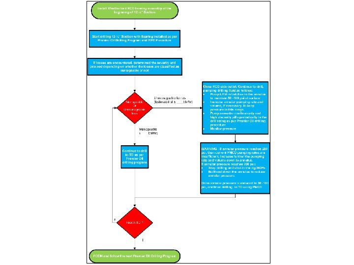
PMCD Decision Tree © 2012 2013 Weatherford. All rights reserved. 21
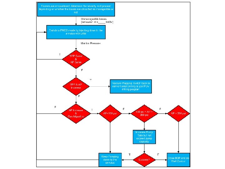
Unmanageable Losses Chart © 2012 2013 Weatherford. All rights reserved. 23
Switching to PMCD • Shutdown drillstring injection. • Line up on of the pump for pumping seawater down the annulus. • Zero stroke counter. Begin annulus injection with minimum of 200 gpm. Monitor RCD surface pressure, the RCD surface pressure should increase as the lower weight seawater displaces the mud in the annulus. Rotate and reciprocate the drillstring if required. • At 150 psi RCD surface pressure, record volume of seawater pumped down the annulus. Stop annulus injection and observe RCD static pressure. Calculate formation pressure and density of LAM required for the operation (plan for 50 to 200 psi RCD surface pressure). © 2012 2013 Weatherford. All rights reserved. 25
Switching to PMCD • Also, evaluate if the cause for RCD pressure increase is due to change in annular fluid density or due to loss zone plugging/fill up. If formation is plugging or filling up, it may be possible to return to conventional drilling. If due to annular fluid density change, continue with next step. • Observe for gas migration and revise calculation for required annulus injection rates. • Resume pumping LAM down the annulus at minimum 100 gpm. • Line up to pump seawater (SAC) down drillstring. • Commence pumping down drillstring at required drill rates for effective hole cleaning. © 2012 2013 Weatherford. All rights reserved. 26
Switching to PMCD • Observe for signs of gas migration with the lowered annulus injection rate. If gas migration is observed, increase pump rate. • If no gas migration observed, stop annulus injection, monitor well and opt for continuous annulus injection. • Commence drilling in PMCD mode. © 2012 2013 Weatherford. All rights reserved. 27
Drilling Ahead with PMCD • Annular fluid must be injected to maintain BHP and stop gas migration. • Pump down drillstring at required drill rates for effective hole cleaning (200 -300 gpm) or as per DSV recommendation. • Maintain annulus pressure within the PMCD well control matrix. • Monitor torque and drag for hole cleaning, pump high-viscosity pill every half stand as per Premier Oil drilling program. • Extra high-viscosity sweeps may be pumped if torque and drag (T&D) become excessive. © 2012 2013 Weatherford. All rights reserved. 28
Drilling Ahead with PMCD • Do not exceed 10 m/hr drilling rate of penetration. • Monitor SPP and Annulus Pressure. • Cementing pump lined up to pump LAM down injection line for emergency. © 2012 2013 Weatherford. All rights reserved. 29
PMCD Drilling – No Injection D R I L L P I P E © 2012 2013 Weatherford. All rights reserved. 30
PMCD Drilling – Injection D R I L L P I P E © 2012 2013 Weatherford. All rights reserved. 31
PMCD Well Control Matrix RCD Surface Pressure Well Control Action 0 to 200 psi Manageable Pressure/ Continue Drilling 200 - 350 psi at 100 rpm Greater than 350 psi Investigate cause of RCD pressure increase. Possible causes are listed but Shut-in on rig BOP. not limited to: Similar to yellow zone, further actions Fractures plugging: switch back to to be taken will depend on the cause conventional drilling (Standpipe of the annulus pressure increase. e. g. pressure will increase) Fracture plugging: Return to Gas migration: increase annulus injection rate Higher than expected pore pressure: increase annulus injection fluid weight conventional drilling Gas migration: bullhead at high rates through the kill line High pore pressure: increase annulus injection fluid weight Green Yellow Red 40% or lesser of the Marine Riser Pressure Rating (500 psi) 40% to 70% of the Marine Riser Pressure Rating Above 70% of the Marine Riser Pressure Rating © 2012 2013 Weatherford. All rights reserved. 32