PRESENTATION ON UNITIV OPTICAL FIBER BY DR S

PRESENTATION ON UNIT-IV OPTICAL FIBER BY DR. S. M. PETHE

What Is Fiber Optics ? • Transmitting communications signals over hair thin strands of glass or plastic • Not a "new" technology • Concept a century old • Used commercially for last 25 years

Fiber Technology n 1 > n 2 n 1 -refractive index of core n 2 -refractive index of cladding

Fiber Technology

n 1 n 2 n 1< n 2 Rarer to denser n 1> n 2 denser to rarer

Critical Angle • Ray bends at boundary between materials – Snell’s law • Light confined to core if propagation angle is greater than the critical angle – Total internal reflection (TIR)

Fiber Types

Fiber Types

Standard Single Mode Optical Fibers • Most common single mode optical fiber: SMF 28 from Corning – Core diameter dcore=8. 2 mm – Outer cladding diameter: dclad=125 mm – Step index – Numerical Aperture NA=0. 14 • NA=sin(q) • Dq=8° • lcutoff = 1260 nm (single mode for l>lcutoff) • Single mode for both l=1300 nm and l=1550 nm standard telecommunications wavelengths

Standard Multimode Optical Fibers • Most common multimode optical fiber: 62. 5/125 from Corning – Core diameter dcore= 62. 5 mm – Outer cladding diameter: dclad=125 mm – Graded index – Numerical Aperture NA=0. 275 • NA=sin(q) • Dq=16° • Many modes

Anatomy of an Optical Fiber • • Light confined to core with higher index of refraction Two analysis approaches – Ray tracing – Field propagation using Maxwell’s equations

Graded Index Multimode Fiber • Higher order modes – Larger propagation length – Travel farther into the cladding – Speed increases with distance away from the core (decreasing index of refraction) – Relative difference in propagation speed is less
")
Numerical Aperture • The acceptance angle for a fiber defines its numerical aperture (NA) • The NA is related to the critical angle of the waveguide and is defined as: • Telecommunications optical fiber n 1~n 2,

Fiber Attenuation • • Loss or attenuation is a limiting parameter in fiber optic systems Fiber optic transmission systems became competitive with electrical transmission lines only when losses were reduced to allow signal transmission over distances greater than 10 km Fiber attenuation can be described by the general relation: where a is the power attenuation coefficient per unit length If Pin power is launched into the fiber, the power remaining after propagating a length L within the fiber Pout is

Fiber Attenuation • Attenuation is conveniently expressed in terms of d. B/km • Power is often expressed in d. Bm (d. Bm is d. B from 1 m. W)

Fiber Attenuation • Example: 10 m. W of power is launched into an optical fiber that has an attenuation of a=0. 6 d. B/km. What is the received power after traveling a distance of 100 km? – Initial power is: Pin = 10 d. Bm – Received power is: Pout= Pin– a L=10 d. Bm – (0. 6)(100) = -50 d. Bm • Example: 8 m. W of power is launched into an optical fiber that has an attenuation of a=0. 6 d. B/km. The received power needs to be -22 d. Bm. What is the maximum transmission distance? – Initial power is: Pin = 10 log 10(8) = 9 d. Bm – Received power is: Pout = 1 m. W 10 -2. 2 = 6. 3 m. W – Pout - Pin = 9 d. Bm - (-22 d. Bm) = 31 d. B = 0. 6 L – L=51. 7 km

Material Absorption • Material absorption – Intrinsic: caused by atomic resonance of the fiber material • Ultra-violet • Infra-red: primary intrinsic absorption for optical communications – Extrinsic: caused by atomic absorptions of external particles in the fiber • Primarily caused by the O-H bond in water that has absorption peaks at l=2. 8, 1. 4, 0. 93, 0. 7 mm • Interaction between O-H bond and Si. O 2 glass at l=1. 24 mm • The most important absorption peaks are at l=1. 4 mm and 1. 24 mm

Scattering Loss • • • There are four primary kinds of scattering loss – Rayleigh scattering is the most important where c. R is the Rayleigh scattering coefficient and is the range from 0. 8 to 1. 0 (d. B/km)·(mm)4 Mie scattering is caused by inhomogeneity in the surface of the waveguide – Mie scattering is typically very small in optical fibers Brillouin and Raman scattering depend on the intensity of the power in the optical fiber – Insignificant unless the power is greater than 100 m. W Geometrical lossare introduce due to the manufacturing process

Absorption and Scattering Loss

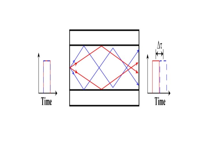
Dispersion • Dispersive medium: velocity of propagation depends on frequency • Dispersion causes temporal pulse spreading – Pulse overlap results in indistinguishable data – Inter symbol interference (ISI) • Dispersion is related to the velocity of the pulse

Fiber Bandwidth

Fiber Bandwidth

THANKS
- Slides: 24