
PRESENTATION ON PROJECT REPORT WASTE HEAT RECOVERY SYSTEM


- Slides: 25
PRESENTATION ON PROJECT REPORT WASTE HEAT RECOVERY SYSTEM FROM DOMESTIC REFRIGERATOR PROJECT INCHARGE Er. Arpit Srivastava Dept. of Mechanical Engineering UIET CSJM University Kanpur BY: GROUP-II FINAL YEAR MECHANICAL DEPARTMENT U. I. E. T C. S. J. M UNIVERSITY KANPUR
Waste Heat Recovery System From Domestic Refrigerator SANDEEP KR. YADAV(272) DEEPAK PATEL(253) YASHWANT KR. JAISWAL(290) KRISHNA PRAKASH(294) MOHAMMAD ADIL(297)
CONTENTS ü Introduction ü Different recovery systems ü System Description ü Design of Heat Exchanger ü Design Of Oven ü Fabrication And Assembly Works ü Results ü Conclusion
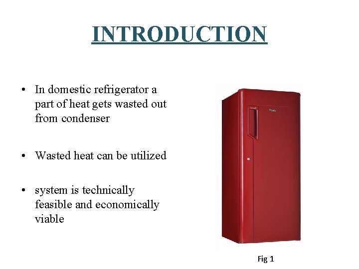
INTRODUCTION • In domestic refrigerator a part of heat gets wasted out from condenser • Wasted heat can be utilized • system is technically feasible and economically viable Fig 1
DIFFERENT HEAT RECOVERY SYSTEM • HRSG in gas power plant or turbine • HVAC in steam power plant • WHRS in refrigeration plant
SYSTEM DESCRIPTION • Tested a WHRS and experimented to recover condensation heat from domestic refrigerator of 165 liter. • By suitably retrofitting the WHRS in the unit , considerable waste heat is recovered. • This heat is utilized for different purposes
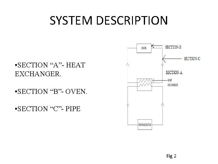
SYSTEM DESCRIPTION • SECTION “A”- HEAT EXCHANGER. • SECTION “B”- OVEN. • SECTION “C”- PIPE Fig 2
HEAT EXCHANGER Ø A heat exchanger is a device used to transfer heat between one or more fluids. The fluids may be separated by a solid wall to prevent mixing or they may be in direct contact. Ø They are widely used in space heating, refrigeration, air conditioning, power stations, chemical plants, petroleum refineries, natural-gas processing, and sewage treatment. Fig 3
CLASSIFICATION OF HEAT EXCHANGER Ø Classification. On the basis of flow (a) Parallel flow (b) Counter flow Fig 4
WHY COUNTER FLOW IN WHRS? The counter-flow heat exchanger has three significant advantages over the parallel flow design: - Ø The more uniform temperature difference between the two fluids minimizes thermal stresses throughout the exchanger. Ø The outlet temperature of the cold fluid can approach the highest temperature of the hot fluid. Ø The more uniform temperature difference produces a more uniform rate of heat transfer throughout the heat exchanger.
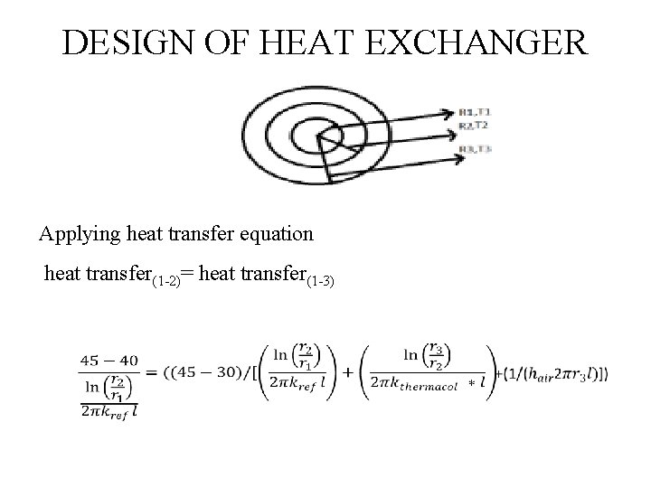
DESIGN OF HEAT EXCHANGER Applying heat transfer equation heat transfer(1 -2)= heat transfer(1 -3)
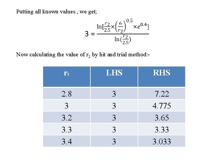
Putting all known values , we get; Now calculating the value of r 2 by hit and trial method: - r 2 2. 8 3 3. 2 3. 3 3. 4 LHS RHS 3 3 3 7. 22 4. 775 3. 65 3. 33 3. 033
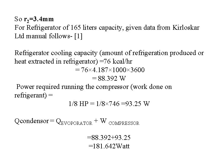
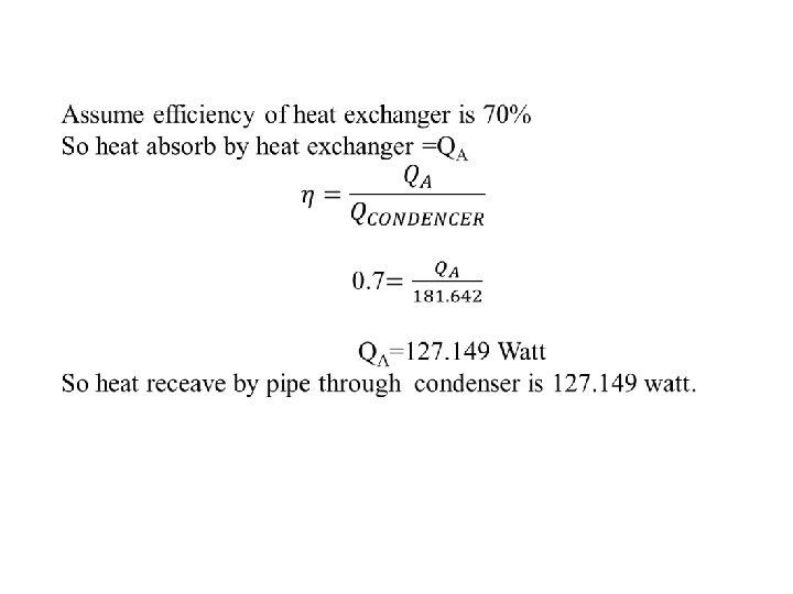
So r 2=3. 4 mm For Refrigerator of 165 liters capacity, given data from Kirloskar Ltd manual follows- [1] Refrigerator cooling capacity (amount of refrigeration produced or heat extracted in refrigerator) =76 kcal/hr = 76× 4. 187× 1000× 3600 = 88. 392 W Power required running the compressor (work done on refrigerant) = 1/8 HP = 1/8× 746 =93. 25 W Qcondensor = QEVOPORATOR + W COMPRESSOR =88. 392+93. 25 =181. 642 Watt
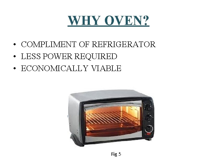
WHY OVEN? • COMPLIMENT OF REFRIGERATOR • LESS POWER REQUIRED • ECONOMICALLY VIABLE Fig 5
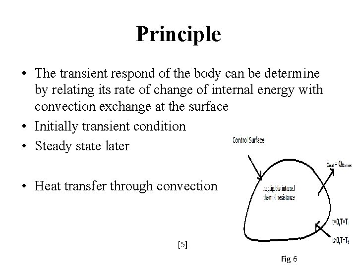
Principle • The transient respond of the body can be determine by relating its rate of change of internal energy with convection exchange at the surface • Initially transient condition • Steady state later • Heat transfer through convection [5] Fig 6
Energy Supply • Oven use low grade energy to work • It use the waste heat, which is release to atmosphere • The refrigerant circulates through tubes ("refrigerant lines") that travel throughout the oven. • This circulated refrigerant dissipate heat to the air inside oven
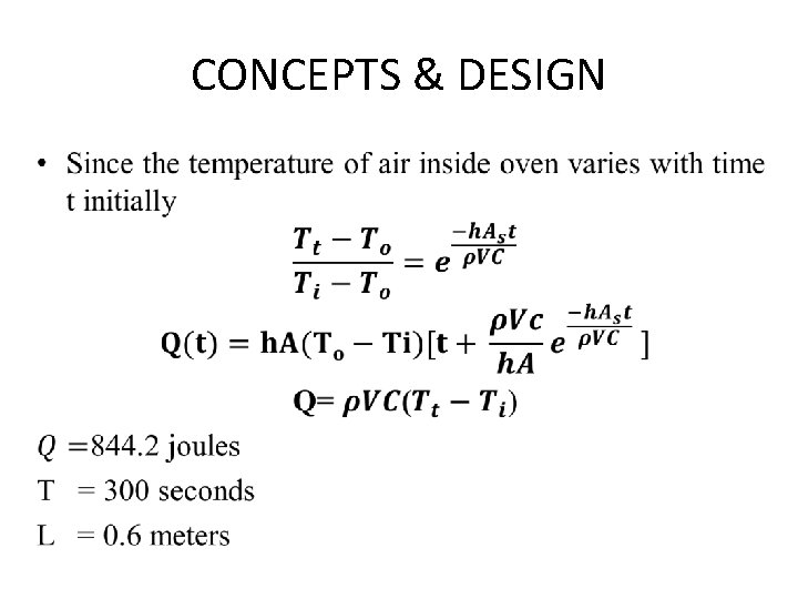
CONCEPTS & DESIGN •
FABRICATION AND ASSEMBLY • Parts of domestic refrigerator are as follows Ø Compressor Ø Modified Air cooled Condenser Ø Capillary Tube Ø Plate type Evaporator Ø Parallel type heat exchanger Ø Insulated pipe Ø Insulated Cabin [4]
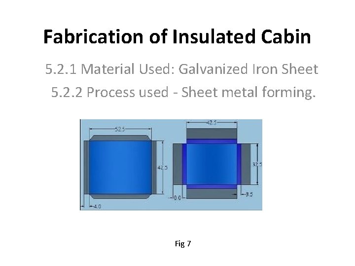
Fabrication of Insulated Cabin 5. 2. 1 Material Used: Galvanized Iron Sheet 5. 2. 2 Process used - Sheet metal forming. Fig 7
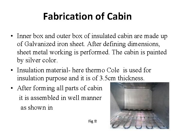
Fabrication of Cabin • Inner box and outer box of insulated cabin are made up of Galvanized iron sheet. After defining dimensions, sheet metal working is performed. The cabin is painted by silver color. • Insulation material- here thermo Cole is used for insulation purpose and it is of 3. 5 cm thickness. • After forming all parts of cabin it is assembled in well manner as shown in Fig 8
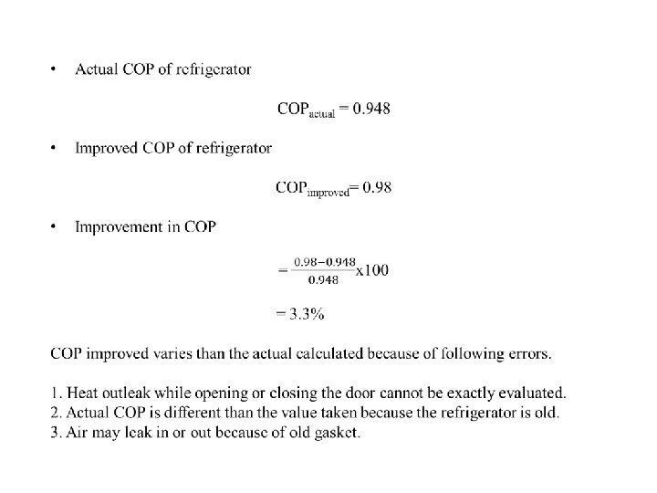
RESULTS • The main aim is to use waste heat for domestic purposes. • Waste heat from condenser is utilised. • All above analysis results in utilisation of waste heat. • COP of refrigerator is also increased.
CONCLUSION Ø Suitable heat recovery system can be designed and developed for every household refrigerator. Ø The experimentation has shown that such a system is practically feasible. Ø Technical analysis has shown that it is economically viable. Ø If this can be started from individual level then it can sum up and enormous effect can be obtained. Thus with small addition in cost if we recover and reuse the waste heat, then definitely we can progress towards energy conservation and simultaneously achieve our day today function. Ø In present situation where everybody in a home is moving out, this combination of refrigerator and food warmer is definitely a boom to efficient house wife.
REFERANCES • [1] S. C. Kaushik, M. Singh. , Feasibility and Design studies for heat recovery from a refrigeration system with a Canopus heat exchanger, Heat Recovery Systems & CHP, Vol. 15(1995)665673. • [2] P. Sathiamurthi, PSS. Srinivasan, Studies on waste heat recovery and utilization. Globally competitive eco-friendly technologies engineering National conference, (2005)39. • [3] P. Sathiamurthi, PSS. Srinivasan “Design and Development of Waste Heat Recovery System for air Conditioning Unit, European Journal of Scientific Research, Vol. 54 No. 1 (2011), pp. 102 -110 • [4] C. P. Arora, Refrigeration and Air conditioning PHI Publications, 2010. • [5] Er. R. K. Rajput, Heat and Mass Transfer, 4 e Mc. Graw Hill Publication 2012 • [6] Design and Development of Waste Heat of domestic refrigerator • [7] Frank P. Incropera and David P. Dewitt, Fundamentals of heat and Mass Transfer 5 e, Wiley India edition, 2008.