
Presentation Compressed Air System Losses in Single Stage
- Slides: 16
Presentation Compressed Air System Losses in Single Stage Centrifugal Compressors Prepared by Barhm Mohamad Faculty of Mechanical Engineering – Hungary https: //www. researchgate. net/profile/Barhm_Mohamad http: //iises. academia. edu/Barhm. Mohamad 1
Compressed Air System Introduction Types of compressors Assessment of a centrifugal compressors Energy efficiency opportunities 2
Introduction Compressor is one of its class of machines in producing Compressed Air System pressure by convert K: E to static pressure , and classified into three types : 1 - high pressure compressor : like Combined axialcentrifugal compressors 2 - medium pressure compressor : like centrifugal compressors (blowers). 3 - low pressure compressor : like axial compressors ( jet engines and gas turbine power plants). There are many type of Compressors: 5 to > 50, 000 hp depending on applications , flow , pressure ratio, frontal area, deliver of pressure and many other 3 aspects.
Introduction Compressed Air System Main Components in Compressed Air Systems • Intake air filters • Inter-stage coolers • After coolers • Air dryers • Moisture drain traps • Receivers 4
Compressed Air System Introduction Types of compressors Assessment of compressors and compressed air systems Energy efficiency opportunities 5
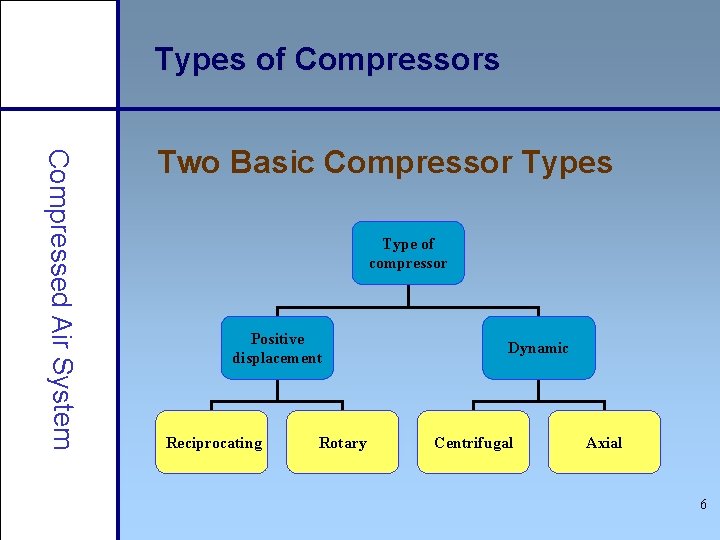
Types of Compressors Compressed Air System Two Basic Compressor Types Type of compressor Positive displacement Reciprocating Rotary Dynamic Centrifugal Axial 6
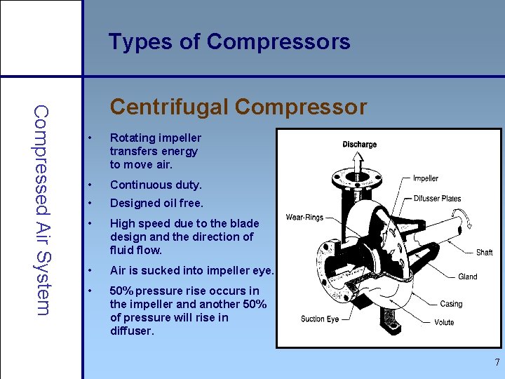
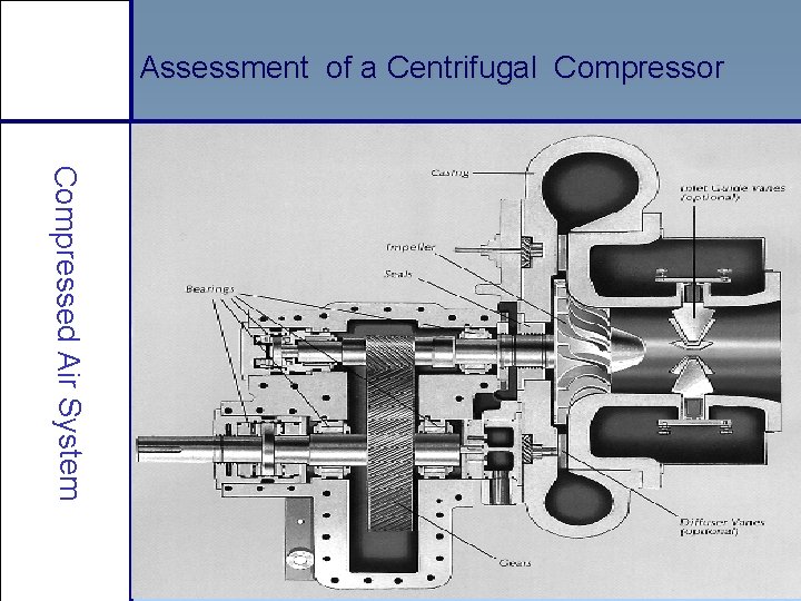
Types of Compressors Compressed Air System Centrifugal Compressor • Rotating impeller transfers energy to move air. • Continuous duty. • Designed oil free. • High speed due to the blade design and the direction of fluid flow. • Air is sucked into impeller eye. • 50% pressure rise occurs in the impeller and another 50% of pressure will rise in diffuser. 7
Compressed Air System Introduction Types of compressors Assessment of a centrifugal compressors Energy efficiency opportunities 8
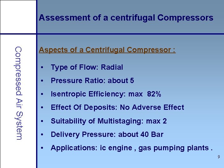
Assessment of a centrifugal Compressors Compressed Air System Aspects of a Centrifugal Compressor : • Type of Flow: Radial • Pressure Ratio: about 5 • Isentropic Efficiency: max 82% • Effect Of Deposits: No Adverse Effect • Suitability of Multistaging: max 2 • Delivery Pressure: about 40 Bar • Applications: ic engine , gas pumping plants. 9
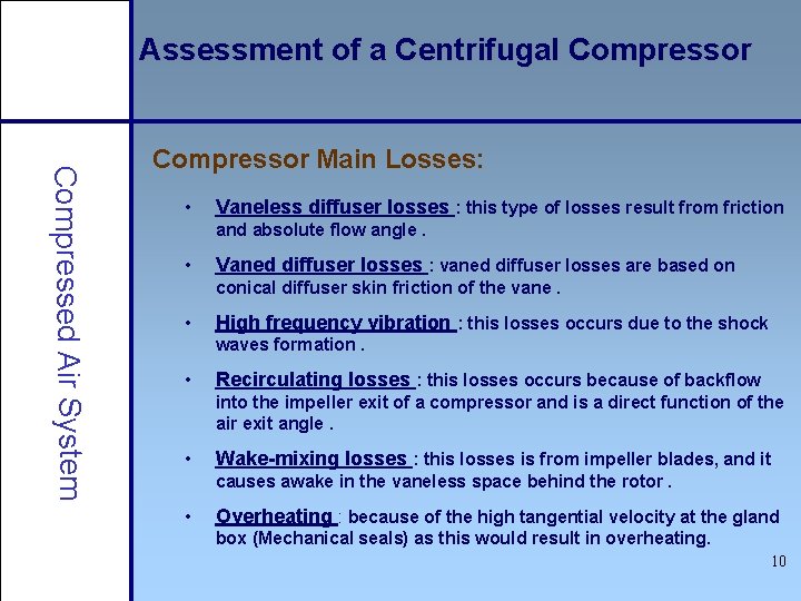
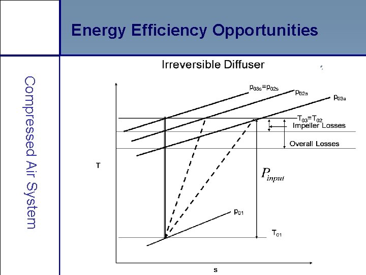
Assessment of a Centrifugal Compressor Compressed Air System Compressor Main Losses: • Vaneless diffuser losses : this type of losses result from friction and absolute flow angle. • Vaned diffuser losses : vaned diffuser losses are based on conical diffuser skin friction of the vane. • High frequency vibration : this losses occurs due to the shock waves formation. • Recirculating losses : this losses occurs because of backflow into the impeller exit of a compressor and is a direct function of the air exit angle. • Wake-mixing losses : this losses is from impeller blades, and it causes awake in the vaneless space behind the rotor. • Overheating : because of the high tangential velocity at the gland box (Mechanical seals) as this would result in overheating. 10
Assessment of a Centrifugal Compressor Compressed Air System 11
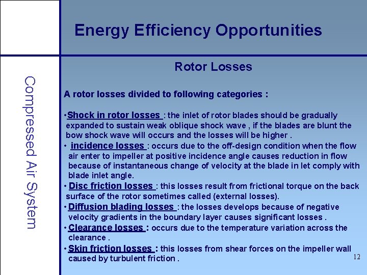
Energy Efficiency Opportunities Rotor Losses Compressed Air System A rotor losses divided to following categories : • Shock in rotor losses : the inlet of rotor blades should be gradually expanded to sustain weak oblique shock wave , if the blades are blunt the bow shock wave will occurs and the losses will be higher. • incidence losses : occurs due to the off-design condition when the flow air enter to impeller at positive incidence angle causes reduction in flow because of instantaneous change of velocity at the blade in let comply with blade inlet angle. • Disc friction losses : this losses result from frictional torque on the back surface of the rotor sometimes called (external losses). • Diffusion blading losses : the losses develops because of negative velocity gradients in the boundary layer causes significant losses. • Clearance losses : occurs due to the temperature variation across the clearance. • Skin friction losses : this losses from shear forces on the impeller wall 12 caused by turbulent friction.
Energy Efficiency Opportunities Compressed Air System 13
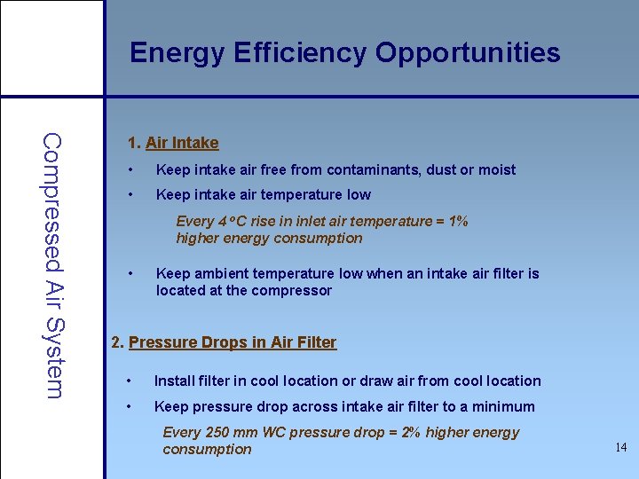
Energy Efficiency Opportunities Compressed Air System 1. Air Intake • Keep intake air free from contaminants, dust or moist • Keep intake air temperature low Every 4 o. C rise in inlet air temperature = 1% higher energy consumption • Keep ambient temperature low when an intake air filter is located at the compressor 2. Pressure Drops in Air Filter • Install filter in cool location or draw air from cool location • Keep pressure drop across intake air filter to a minimum Every 250 mm WC pressure drop = 2% higher energy consumption 14
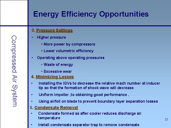
Energy Efficiency Opportunities 3. Pressure Settings Compressed Air System • Higher pressure • More power by compressors • Lower volumetric efficiency • Operating above operating pressures • Waste of energy • Excessive wear 4. Minimizing Losses • Installing the IGVs to decrease the relative mach number at inducer tip so that the formation of shock wave will decrease • Uniform impeller , to obtaining good performance. • Using airfoil on blade to prevent boundary layer separation losses 5. Condensate Removal • • Condensate formed as after-cooler reduces discharge air temperature Install condensate separator trap to remove condensate 15
The End Compressed Air System ü Losses in Single Stage Centrifugal Compressors THANK YOU FOR YOUR ATTENTION 16