Presence PLUS P 4 GEO Customer Workshop Presence


![Status Bar Value: 31 [615, 436] Cursor Position Gray Scale Value Address 1: 1](https://slidetodoc.com/presentation_image_h/f7b3b6c25fd285b7de5759bad26a91e0/image-24.jpg "Status Bar Value: 31 [615, 436] Cursor Position Gray Scale Value Address 1: 1")
 Shows Selected")

 n General Output (tie to TEST")


 – The Amount")


 X speed (in/sec)")
 X 1000 (ms/sec) Exposure Time = (ms) 640")


 n Mask any Area of the Geometric Count")


 But First. . .")


 Product Select Input (Pin 5, 6,")


 to Include More Edge")


 xxxx To Connect to the Vision Phone:")


")


![PC Programs to Display Data Telnet n Start > Run > [IP address] [port]](https://slidetodoc.com/presentation_image_h/f7b3b6c25fd285b7de5759bad26a91e0/image-129.jpg "PC Programs to Display Data Telnet n Start > Run > [IP address] [port]")


- Slides: 131
Presence. PLUS® P 4 GEO Customer Workshop
Presence. PLUS® P 4 GEO Workshop Agenda n Introduction to Machine Vision Technology n Banner Vision Mission and Offering n Setting up a P 4 GEO Inspection – Hardware – GUI Navigation – Trouble Shooting n Best Practices for Applying the Geometric Count Tool n Your Applications Q/A
Machine Vision Applications n LOT 24 Verification LOT 24 n n Presence/Absence Gauging/Measuring LOT X 24 LOT 24 n Orientation n Flaw Detection LOT 24 n Sorting LOT 25
What is Machine Vision? Computerized Light Measurement to Error Proof Production Processes
Camera CCD – Charged Coupled Device Pixel – Picture Element 128 Pixels 100 Pixels 1/3" CCD Array 12, 800 Pixels Image Sensor
The Image is Converted to Pixels 640 x 480 image
Convert Signal to Gray Scale Volts CCD Voltage = 1. 0 Brightest = 255 CCD Voltage =. 5 Mid Gray = 128 CCD Voltage = 0 Black = 0 Gray Scale
Lighting Control is Critical Backlight Low Angle Directional Dome Light Ring Light On Axis
What Are You Trying to Maximize When You Apply a Vision Sensor? CONTRAST ‘Good’ Condition ‘Bad’ Condition
Banner Vision Division Make Machine Vision Technology Affordable and Practical for Routine Factory Floor Inspections n Performance – Reliably Solve Inspections n Ease of Use n Value
Banner: More Sensors, More Solutions
Presence. PLUS® Vision Sensor Line Introduced in 2000 Presence. PLUS® Pixel Counting Sensor Presence. PLUS®Pro Full Function Vision Sensor Presence. PLUS® P 4 GEO Single Function Sensor
Presence. PLUS® P 4 GEO Setting Up an Inspection
Presence. PLUS® P 4 Hardware 12 Wire Power and I/O Cable 10/100 Ethernet NTSC Connector for Live Video PICO Connector for Banner LED Light – 24 V dc and Strobe Control
P 4 Platform Connections n 10 30 V dc n 4 Discrete I/O – User Defined (input or output) – User Programmable (PNP or NPN) n 10/100 Ethernet & Serial Interfaces – 10 Ethernet Ports – 1 RS 232 Port n Pico Connector on Sensor Provides Power for Light Source and has Connection for Strobe Control Output
Presence. PLUS® P 4 Wiring 1 2 3 4 5 6 7 8 9 10 11 12 RS 232 TX Remote Teach Product Change External Trigger I/O #1 I/O #2 I/O #3 I/O #4 RS 232 RX RS 232 Ground DC Common 10 30 V dc Output Input In/Out In/Out Output Input
Presence. PLUS® P 4 GEO Indicators n Bi Colored Status Indicators – Green = PASS Red = FAIL – Green = POWER Red = ERROR – Green = READY Yellow = TRIGGER n Lens – Standard C Mount n Housing – Black Anodized Aluminum – IP 20 Environmental Rating
Install the GUI Software on Your PC n Load the PC Software Using the Automatic Installer on the CD ROM n Presence. PLUS 2. 0. 1 Works in 9 Major Languages and on All Presence. PLUS Sensors n Free Updates Available on bannerengineering. com
Step 1 Check the Hardware Connection The Yellow LED on the Back of the Sensor Should be On If Yellow LED is off check cable connections, status of Ethernet port on the PC and power supplied to the P 4 Sensor
Step 2 Change the IP Address of the PC n Set the PC Subnet to match the factory default address of the Presence. PLUS sensor IP Address 192. 168. 0. 2 Subnet Mask 255. 0
Getting to the TCP/IP Properties Window Takes a Few Steps Setup and Configuration Notes for Changing the IP Address for Each Windows Operating System in your Workshop Binder
Presence. PLUS® Software
Presence. PLUS® GUI 7 Buttons – No Pull Down Menus to Hunt Through Configuration Window Toggle Switch Icons Results Window Image Window Status Bar
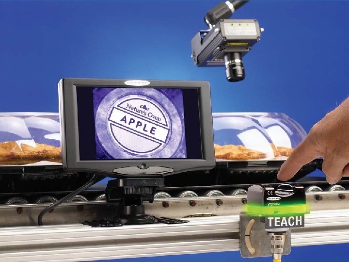
Status Bar Value: 31 [615, 436] Cursor Position Gray Scale Value Address 1: 1 Current Displayed Image Resolution (compression)
Toggle Switch Icons Zoom (left click zoom in right click zoom out) Shows Selected Tool ROI/ ”A” Shows all Tools ROIs Expand Window Delete Selected Tool and All Subsequent Tools
The System Tab
I/O Options – Function n General Input (default) n General Output (tie to TEST tool results) n Pass (latch only) n Fail (latch only) n System Error (latch only) n Ready (latch only) n Product Select (use in conjunction with the orange product change line)
Input Options Trigger, Remote Teach, Product Change and General Input n NPN (Current Sourcing, Default Setting) n PNP (Current Sinking)
General Output n 150 m. A – Use a Relay if Trying to Connect to Solenoid or other Device with a Load Above 150 m. A n Electrical: Current Sinking/NPN (default) or Current Sourcing/PNP n Normally: Open (default) or Closed n Output Delay: 0 (default) – 10, 000 ms n Output Duration: Latched (default) or Pulsed from 1 10, 000 ms
Output Options Pass, Fail, System Error, Ready n System Outputs – Will Stay the Same with Every Inspection – Only Latched and No Delay – Everything Else is Configurable – For Best Engineering Practices Monitor to the Ready (not busy) Output – If Using Pass or Fail Outputs, Monitor a Ready Output to Insure Inspections are Continuing to Operate
Latched Output Pass Output ON OFF Sensors Status Inspect Idle Pass Fail
Strobe n If Exposure Time is < 1 ms Configure Strobe Tab to “On” (Default)
Steps For Creating an Inspection – Position, Focus and Adjust Lighting to Create Reference Image SETUP Add – – To: Find the Part – Location Tool (rarely used) Analyze the Part – Geometric Count Tool Measure the Part – Measure Tool Set / Criteria Test Tool (required) TOOLS TEACH RUN Automatically Configure Values for Good Parts (optional) The Inspection
Setup Screen
Get an Image Focus Tab n Trigger Type n Focus n Image Brightness n Resolution
Get an Image – Trigger n Continuous – The Presence. PLUS Pro Software will Trigger the Camera to Snap Pictures as Fast as Possible n External – The Camera Waits for an Electrical Signal from the Trigger Input to Snap a Picture n Manual – The Camera Waits for the Manual Button on the Software to be Clicked to Snap a Picture n Off – The Camera will Not Acquire Images
Get an Image Focus n The Focus Number Represents the Image’s Contrast Level – High Contrast – Higher Focus Number – Low Contrast – Lower Focus Number n Turn the Lens Focus Adjustment Ring as the Focus Number Increases; Turn the Ring the other Direction when the Focus Number Starts to Decrease
Get an Image – Image Intensity n Exposure Time (electronic shutter) – The Amount of Time the CCD Image Chip is Exposed to Light –. 01 ms to 20. 47 ms n Gain – Electronically Boosting the Light (and the Noise) Sensed by the CMOS Imager n Use Auto Exposure; Tweak, if Necessary
Get an Image – Exposure Time n Determines the Amount of Light Needed for an Inspection n Determines How Fast a Part can Move Past the Camera While an Image is Being Captured n For Moving Targets Minimize Exposure Time by Opening the Aperture and Increasing the Gain n For Indexed Targets Leave the Gain at 20 and Adjust Exposure for the Light Needed for Adequate Contrast
Affecting Blur 10 5 ms 2 ms 1
Blur Calculation Example Pixel Blur = 640 Pixels X Exp. (ms) X speed (in/sec) FOV (in) X 1000 (ms/in) Part is 4 inches wide and is moving at 40 in/sec (200 ft/min). The exposure time is 1 ms. Pixel Blur = 640 Pixels X 1 (ms) X 40 (in/sec) 4 (in) X 1000 (ms/in) = 6. 4 Pixels At 1 ms There is a 6 Pixel Blur!
Exposure Time Calculation Maximum FOV (inches) X 1000 (ms/sec) Exposure Time = (ms) 640 Pixels X Speed (inches/sec) Part is Moving at 200 Ft/Min and is 4 Inches Wide Maximum 4 (inches) X 1000 (ms/sec) Exposure Time = (ms) 640 Pixels X 40 (inches/sec) =. 16 ms
Tools Screen Tool Overview
Location Tools n Not Required for Typical P 4 GEO Inspection – Useful for Positioning ROI When Using Remote Teach Function – Locate Combined with a Smaller Geometric Count Search Area will Speed Inspection Time n Compensates for Translational and Rotational Movement of the Inspection Target n Used to Move Regions of Interest (ROIs) that Follow the Location Tool n Two Types – Geometric Find – Locate
Vision Tool – Geometric Count n The Geometric Count Tool Searches For Matching Patterns n Workhorse of the P 4 GEO Sensor
Measure Tool n Measure Tool is Used to Measure the Distance Between the Center of Patterns, Edges Found with the Locate Tool or the Sensor’s Origin n The Absolute Distance as well as the Horizontal (x) or Vertical (y) Distance in Pixels is Found
Test Tools n Evaluates Results of Selected Vision and Analysis Tools n Activates Outputs n Determines Tolerances for when an Inspection Passes or Fails n Performs Logical Operations n At Least 1 Test Tool is Required for an Inspection
Communications n Use the Test Tool to Configure Discrete Outputs (Black, Red, White and Light Blue Wires) n Use the Communications Tool to Send any Inspection Information out the Ethernet Port and/or the RS 232 Serial Port
Geometric Count Tool
Geometric Count Tool – ROI Selection Chose a Rectangular, Elliptical or Circular ROI
Geometric Count Tool Add Masks (Optional) n Mask any Area of the Geometric Count ROI that is NOT a Critical Pattern Feature n Add up to Eight Masks
Test Tool
Test Tool Configuration n Four Inputs Configured as Either: – Geometric Count Tools – Measure Tools – External Inputs – Previous Test Tools n Logically Tie the Inputs Together n Turn on Outputs
Test Results n The Results Can be Used: – As an Input to Another Test – To Turn on an Output – To Contribute to Passing or Failing an Inspection – Or All of the Above
Quick Teach
Quick Teach n Populates Test Tool Input Tabs with Values Such that the Reference Image will Pass n In a Typical P 4 GEO Inspection, Quick Teach Fills in the Geometric Pattern Count Input of the Test Tool with a Min 1 and a Max 1
Run (Run Screen) But First. . .
Save In Between Quick Teach and Run Save the Inspection on the Controller
Run n Select the Inspection n Start/Stop the Inspection n Choose Inspection Capture Method n Set Fail Capture Time on NTSC Video Monitor n Clear Inspection Count n View Discrete I/O n View Results
Run – Results Screen n Inspection Parameters – Camera – Trigger n Run Parameters – Tool Inputs and Results – Test Tool Inputs and Results
Run – Results Screen Expand Test Tool to See More
Run – The Inspmgr n View Sensor Response Time n Includes Compete Inspection Time from Trigger Initiation to Output
Lab 1 – WORLD BEAM® Targets n Goal – Build a Basic Inspection – Quick Teach Inspection – Save Inspection – Run Inspection and View Results
Remote Teach Update P 4 GEO On the Fly
Two Flavors of Remote Teach the Pattern Remote Teach the Quantity
Remote Teach – Tools Affected RT Affects Pattern RT Affects Min/Max
Remote Teach Timing Diagram Trigger Ready Remote Teach Existing Inspection Occurs Here Remote Teach is Activated Remote Teach Occurs Here New Target Must in Place New Inspection Occurs Here
Product Change From One Inspection to Another On the Fly
Product Change Timing Product Change Input (Pin 3) Product Select Input (Pin 5, 6, 7, or 8) Start Counting Pulses on Product Select Line n Pulse this Line to Increment Inspection Address Stop Counting Pulses on Product Select Line This Pulse Would Not be Counted Example: – The Sensor will Stop Executing the Inspection it is Currently Running, – Go to Address Number 4, – Load the Inspection at Location 4, – Enter RUN Mode, – Execute the Inspection on the Next Valid Trigger n Sensor Should be in Ready Mode and not Running an Inspection When Making a Product Change Request
Geometric Count Tool n How it Works n Best Practices for Configuring
Tools Menu
P 4 Tool Screen Shot n Geometric Count Tool – Intelligent Edge Extraction
360 o Rotation = OK
Occluded Object = OK
Overlapping Objects = OK
Multiple Targets = OK
ROIs Outside of FOV = OK
Changing Light Levels …
Pattern ROI Search ROI
n Input Tab – Establish Geometric Count Tool
n Advanced Tab – Increase or Decrease Pattern Rotation – Change to More Exact Pattern Match
Geometric Count Defaults = Forgiving Application May Require a More Discerning Search; Use Extra Edges and Missing Edges Filter n Example: – Look at Date/Lot Code on Container to Determine: n Presence/Absence vs. n Date/Lot Code Being Correct
Geometric Count Default Settings Good Product Passes
Geometric Count Default Settings Different Product Passes
Geometric Count Default Settings Different Product Passes
What If Customer Wants to Make the Inspect for an Exact Pattern Match? n Previous Application did Determine Presence/ Absence Correctly n Minimum Acceptance Level Adjustment will Not Fail Bad Products n Must Go into Advanced Tab
Lot Date Code Application n Turn on Extra Edges n Turn on Missing Edges
Geometric Count Configured To Check for Extra and Missing Edges Good Product Passes
Geometric Count Configured To Check for Extra and Missing Edges Different Product Fails Missing Edges
Geometric Count Configured To Check for Extra and Missing Edges Different Product Fails Extra Edges
Methods to Speed Inspection n Increase ROI Size (red box) to Include More Edge Content n Reduce Edge Content outside the Pattern Area of the FOV (Field of View) n Reduce Rotation Range n Reduce Search Area ROI (yellow box)
Lab 2 – Date Code Targets n Learn How Remote Teach Works n Learn How to use Extra and Missing Edges for a More Exacting Inspection n Learn How ROI Content, Rotation Range, and Search Area Size Affect Inspection Speed
Inspection Logging Using the Log Tab to Trouble Shoot
Log Options n Default None, Image Enable Unchecked n Chose Pass, Fail, Any n Or to Troubleshoot Remote Teach Choose RT or RT Fail n Select Strategy – 1 st 10 Inspections – Last 10 Inspections – First 5 and Last 5
Obtain Images and View Results n Shows Image and Inspection Results for All Logged Inspections n Can Save to PC or Load Saved Inspections From the PC
Teach How Teach Works
Teach n Trigger Good Products n Test Tool Parameter Windows will Expand so that all Taught Products will Pass n Teach Never Narrows Test Tool Parameter Windows n Teach Overwrites Any Values (including manually entered values) n Best Practices – Use Teach Than in Run Verify Best Bad Products Fail n If Required, Tweak Test Tools Manually
Locate Tools
Most P 4 GEO Applications Require No Locate Tool Two Instances to Use a Locate Tool: n Increase Speed – Decrease Geometric Count Search ROI – Place Search Window in Accordance with a Located Edge Feature n Place Geometric Count ROI During Remote Teach – Locate Tool Executes Prior to Remote Teaching of Geometric Count Tool – Geometric Count ROI Placed in Reference to Target Feature For Consistency
Locate Tool: Part Moves but is Still Good Part Finds the Edge and Adjusts Subsequent Vision Tool ROIs
Locate – Configuration n Threshold Type n Threshold Level n Polarity n ROI Width n Smooth Filter n Minimum Width n Sample Rate
Locate – Configuration Threshold Types n Absolute Threshold n Relative Threshold n Edge Strength
Locate – Configuration Relative Threshold n n An Edge is Found When the ROI Detects Pixels That Pass a Gray Scale Percent Locate Only Uses the First Edge Threshold Edges = ROI Profile
Locate – Configuration Relative Threshold n Advantages – Tolerant to Light Fluctuations Between Inspection n Disadvantage – Can Find False Edges
False Edge Example
Locate – Configuration Threshold Level n This Option Moves the Threshold Level (the green line on the graph)
Locate – Configuration Polarity Options Bright to Dark to Bright ALL
Locate – Configuration Enable Rotation n Activates the Edge Angle Calculation n The Position of the ROIs That Follow will Adjust for Both Translation and Rotation n Enable Rotation Requires an ROI Width of 13 A Width of 21 or Greater is Recommended
Locate Results n Results Used by Test Tool – None n Results Used by the Measure Tool – First Edge Found – Must be Used in Conjunction with Another Vision Tool
Presence. PLUS® Communications
Networking Basics n What is a Network? – An Interconnected or Interrelated Chain, Group, or System n Two Common Networks Are: – World Wide Web – Telephone System
Networking Basics Components of a Network – Telephone Application Voice Converter Voice/Electric Signal Voice Converter Physical Medium
Networking Basics Components of a Network – Ethernet Cat 5 e Cable Ethernet Port B A PC PC Software Ethernet Card Data Collection C P+Pro Software
Networking Basics n How Does the PC Find the Pro? – Through the TCP/IP Address n What is TCP/IP? – Transmission Control Protocol/Internet Protocol – A Set of Software Standards to Establish Communications Between Two Computers
The Telephone Address System Phone Numbers (xxx) xxxx To Connect to the Vision Phone: Call 001. 763. 544. 3164 ext. 3067 Country Code Area Code Banner Vision Extension 001 763 544. 3164 3067
The Network Address System IP Address xxx To Email to the Vision Computer: 192. 168. 104 Port 110 Vision Network Vision Computer POP 3 Mail 192. 168. 0. 104 110
Networking Basics n When We Set up the TCP/ IP Setting on a Computer, We Need to Know Two Things: – IP Address – Subnet Mask n Subnet Mask is Used to Separate the Two Parts of the IP Address, the Extended Network Prefix and the Host Address
Subnet Mask Most Common Subnet Values n 255, Used to Indicate the Static Network Numbers n 0, Used to Indicate the Variable Host (PC) Numbers
Subnet Mask The Subnet Mask Determines the Maximum Number of Devices per Network Size 255 Nodes 65000 Nodes Subnet 255. 0 255. 0. 0 Computer A 192. 168. 0. 11 192. 168. 1. 11 Computer B 192. 168. 0. 121 192. 168. 23. 11 Computer C 192. 168. 0. 5 192. 168. 0. 35 Computer D 192. 168. 0. 240 192. 168. 23. 2
Pro Communications Ports A PC 192. 168. 0. 104 Data Collection 192. 168. 0. 2 Port 23 B P+Pro 192. 168. 0. 1 C GUI Port 20000 Comm Port
Ethernet TCP/IP and Serial Communication Port(s)
Communication Tool Steps n Create an Inspection n Add a Communication Tool – Choose the Vision Tool With the Data – Choose the Specific Data to Send – Choose Which Port to Send it Through – Choose How to Format the Message
Choose the Vision Tool
Select the Data Order of the Data – Left to Right, Top to Bottom
Choose the Port
Format the String n Delimiters – , : ; space <cr> <lf> <cr lf> <lf cr> n Start String, End String n Enable Labels
PC Programs to Display Data Telnet n Start > Run > [IP address] [port] – [192. 168. 0. 1] [20000]
PC Programs to Display Data Hyper. Terminal n Start New Session n Choose – Icon – Winsock (TCP/IP) – Host Address 192. 168. 0. 1 – Port 20000
Presence. PLUS® P 4 GEO Customer Workshop