
Preprocessing Realigning and Unwarping Methods for Dummies 201516

- Slides: 31
Preprocessing: Realigning and Unwarping Methods for Dummies, 2015/16 Sujatha Krishnan-Barman Filip Gesiarz
What this talk covers • Preprocessing in f. MRI : Why is it needed? • Motion in f. MRI • Realignment • Unwarping • How this all works in SPM Suze Filip
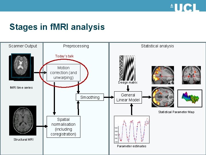
Stages in f. MRI analysis Scanner Output Preprocessing Statistical analysis Today’s talk Motion correction (and unwarping) Design matrix f. MRI time series Smoothing General Linear Model Statistical Parameter Map Spatial normalisation (including coregistration) Structural MRI Parameter estimates
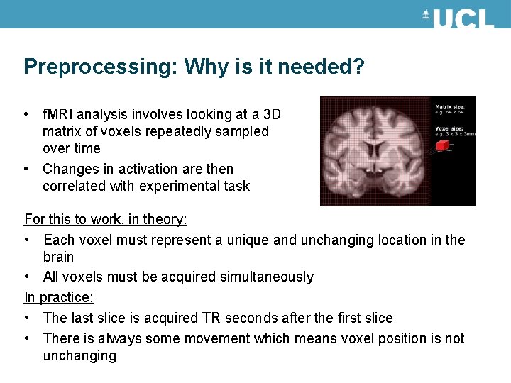
Preprocessing: Why is it needed? • f. MRI analysis involves looking at a 3 D matrix of voxels repeatedly sampled over time • Changes in activation are then correlated with experimental task For this to work, in theory: • Each voxel must represent a unique and unchanging location in the brain • All voxels must be acquired simultaneously In practice: • The last slice is acquired TR seconds after the first slice • There is always some movement which means voxel position is not unchanging
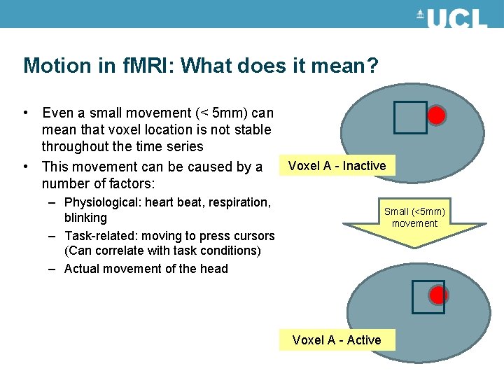
Motion in f. MRI: What does it mean? • Even a small movement (< 5 mm) can mean that voxel location is not stable throughout the time series • This movement can be caused by a Voxel A - Inactive number of factors: – Physiological: heart beat, respiration, blinking – Task-related: moving to press cursors (Can correlate with task conditions) – Actual movement of the head Small (<5 mm) movement Voxel A - Active
Motion in f. MRI: Why is it bad? • Movement of voxel position through the task can lead to false activations • These movement-induced variances can often be much larger than experiment-induced variance • The movement induced by the task (pressing a cursor, moving joystick) can often correlate with conditions These movements increase noise, lowering signal-to-noise ratio Our objective in motion-reduction and motion-correction is to remove the uninteresting variability and improve the SNR
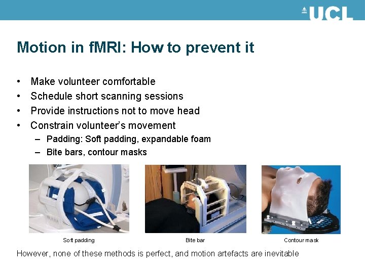
Motion in f. MRI: How to prevent it • • Make volunteer comfortable Schedule short scanning sessions Provide instructions not to move head Constrain volunteer’s movement – Padding: Soft padding, expandable foam – Bite bars, contour masks Soft padding Bite bar Contour mask However, none of these methods is perfect, and motion artefacts are inevitable
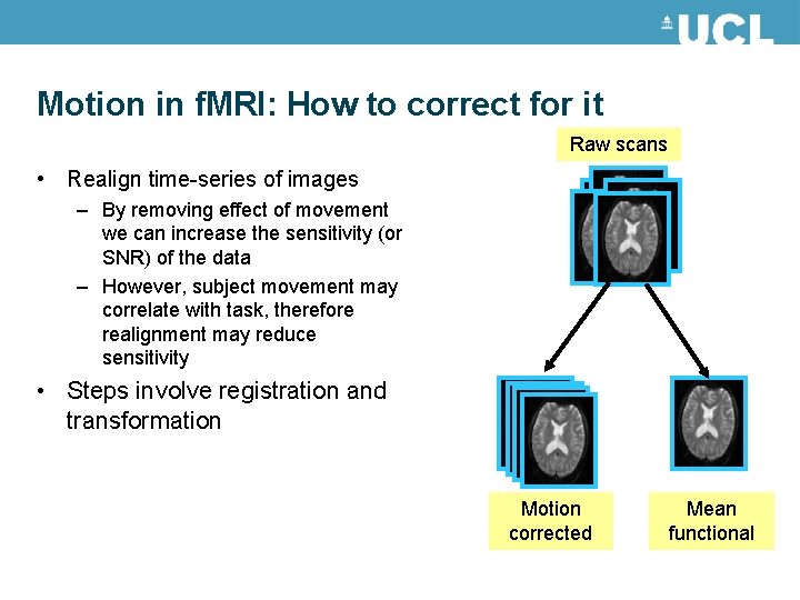
Motion in f. MRI: How to correct for it Raw scans • Realign time-series of images – By removing effect of movement we can increase the sensitivity (or SNR) of the data – However, subject movement may correlate with task, therefore realignment may reduce sensitivity • Steps involve registration and transformation Motion corrected Mean functional
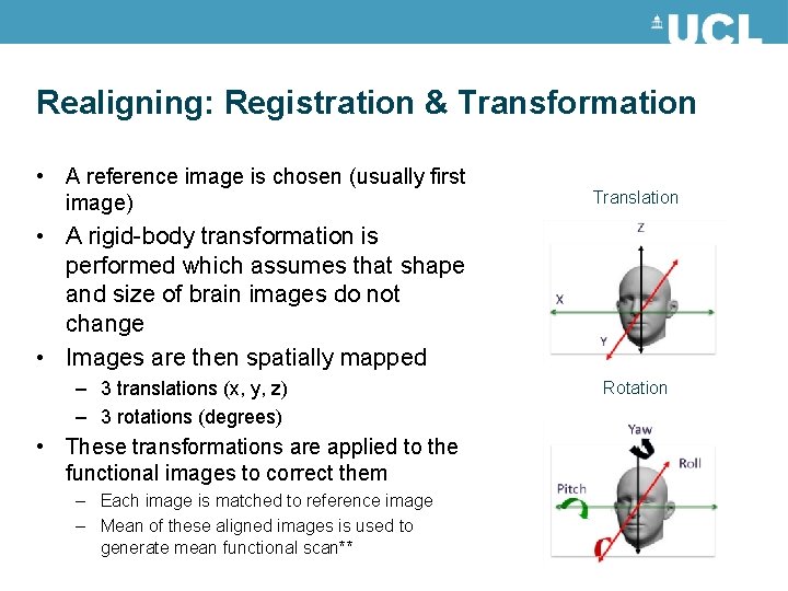
Realigning: Registration & Transformation • A reference image is chosen (usually first image) Translation • A rigid-body transformation is performed which assumes that shape and size of brain images do not change • Images are then spatially mapped – 3 translations (x, y, z) – 3 rotations (degrees) • These transformations are applied to the functional images to correct them – Each image is matched to reference image – Mean of these aligned images is used to generate mean functional scan** Rotation
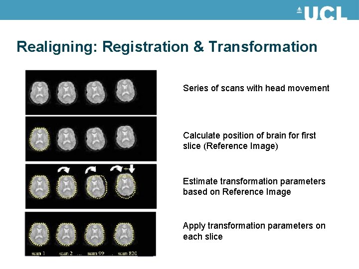
Realigning: Registration & Transformation Series of scans with head movement Calculate position of brain for first slice (Reference Image) Estimate transformation parameters based on Reference Image Apply transformation parameters on each slice
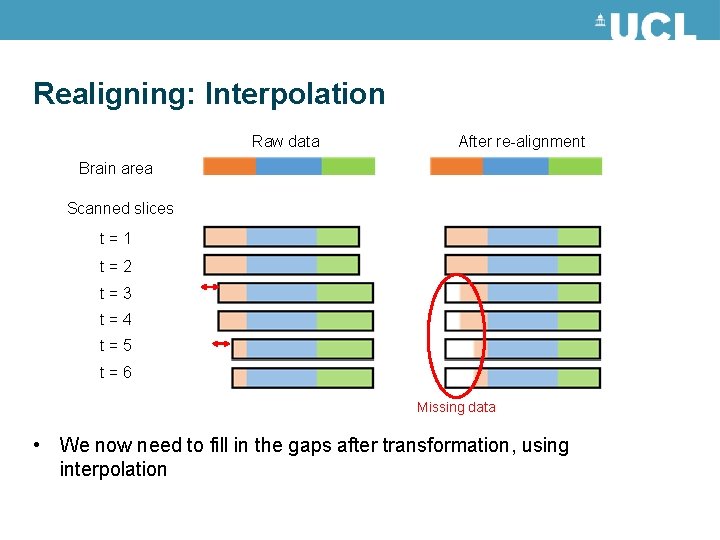
Realigning: Interpolation Raw data After re-alignment Brain area Scanned slices t = 1 t = 2 t = 3 t = 4 t = 5 t = 6 Missing data • We now need to fill in the gaps after transformation, using interpolation
Realigning: Interpolation • • Interpolation involves constructing new data points based on known data Simple interpolation: – Nearest neighbour: Take value of closest voxel – Tri-linear: Take weighted average of neighbouring voxels • B-Spline interpolation – Improves accuracy – SPM uses this as standard • There may still be residual errors…
References and further reading • Slides from previous years of the Mf. D course (http: //www. fil. ion. ucl. ac. uk/mfd/) • MRC CBU Cambridge, Imaging Wiki (http: //imaging. mrc-cbu. cam. ac. uk/imaging) • Nipype Beginner’s guide to neuroimaging (http: //miykael. github. io/nipype-beginner-s-guide/neuroimaging. html) • Andy’s Brain blog (http: //andysbrainblogspot. co. uk/2012/10/fmri-motion-correction-afnis -3 dvolreg. html) Also has cool video showing the 3 translations and 3 rotations. • Huettel, S. A. , Song, A. W. , & Mc. Carthy, G. (2004). Functional magnetic resonance imaging. Sunderland: Sinauer Associates.
After realignment Even after realignment there is considerable residual variance in f. MRI time series that covary with, and is most probably caused by, subject movements. Result: - Loss of sensitivity (false negatives) - Mistaking movement induced variance for true activations (false positives)
Known issues • Spin-history effects: In a typical FMRI design, the TR is not much larger than the T 1, and so the spins will not relax back completely by the time the next acquisition arrives. If there is a sudden motion in the subject half way through a scan, a particular slice may correspond to a different part of brain than it did last time. It will be in a different degree of excitation, and the signal intensity will be different. • Slice-to-vol effects: The rigid-body model that is used by most motion-correction (e. g. SPM) methods assume that the subject remains perfectly still for the duration of one scan (a few seconds) and that any movement will occurr in the few μs/ms while the scanner is preparing for next volume.
Known issues • Susceptibility-distortion-by-movement interaction: susceptibility induced field inhomogenity will cause distortions of the image • Susceptibility-dropout-by-movement interaction: The susceptibility induced field inhomogenity will cause signal loss due to through -plane dephasing
Inhomogenity of magnetic field Magnetic susceptibility (χ) - degree of magnetization of a material in response to an applied magnetic field. If χ is positive, a material can be paramagnetic - the magnetic field in the material is strengthened by the induced magnetization. If χ is negative, the material is diamagnetic - the magnetic field in the material is weakened by the induced magnetization.
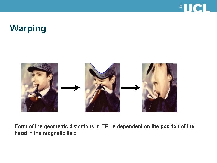
Warping Form of the geometric distortions in EPI is dependent on the position of the head in the magnetic field
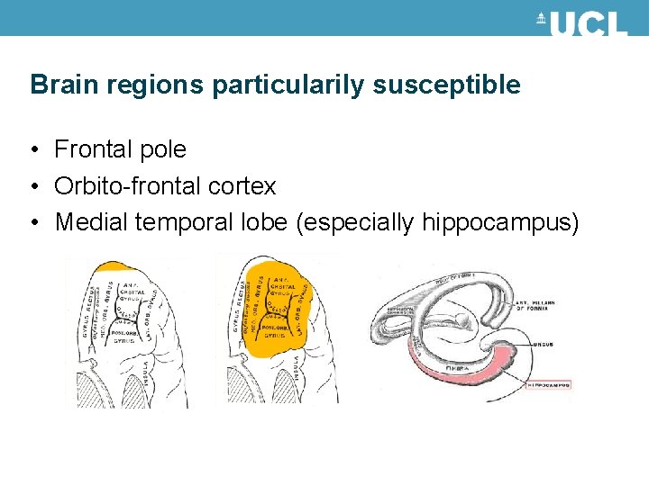
Brain regions particularily susceptible • Frontal pole • Orbito-frontal cortex • Medial temporal lobe (especially hippocampus)
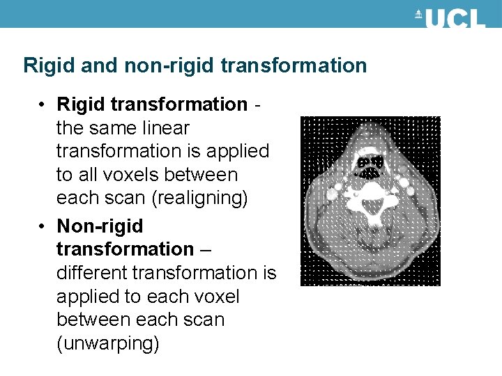
Rigid and non-rigid transformation • Rigid transformation - the same linear transformation is applied to all voxels between each scan (realigning) • Non-rigid transformation – different transformation is applied to each voxel between each scan (unwarping)
Unwarping • For given time series and subject’s changes position we observe variance in signal (after realignment) • Given observed variance and subjects changes in position, what is the change in deformation?
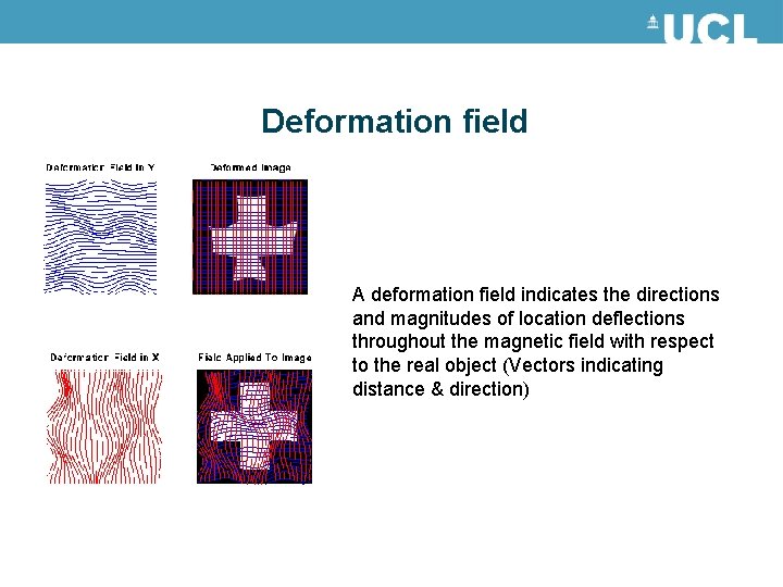
Deformation field A deformation field indicates the directions and magnitudes of location deflections throughout the magnetic field with respect to the real object (Vectors indicating distance & direction)
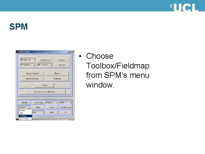
SPM • Choose Toolbox/Fieldmap from SPM’s menu window.
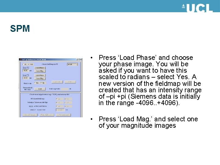
SPM • Press ‘Load Phase’ and choose your phase image. You will be asked if you want to have this scaled to radians – select Yes. A new version of the fieldmap will be created that has an intensity range of –pi +pi (Siemens data is initially in the range -4096. . +4096). • Press ‘Load Mag. ’ and select one of your magnitude images
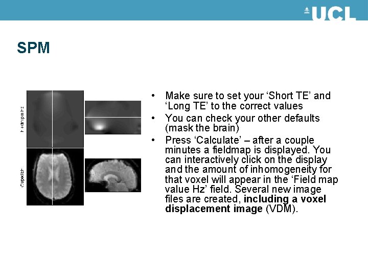
SPM • Make sure to set your ‘Short TE’ and ‘Long TE’ to the correct values • You can check your other defaults (mask the brain) • Press ‘Calculate’ – after a couple minutes a fieldmap is displayed. You can interactively click on the display and the amount of inhomogeneity for that voxel will appear in the ‘Field map value Hz’ field. Several new image files are created, including a voxel displacement image (VDM).
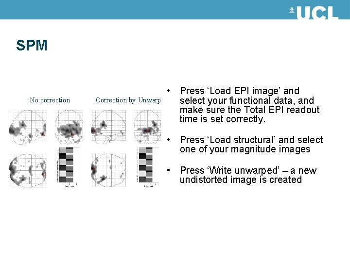
SPM No correction Correction by Unwarp • Press ‘Load EPI image’ and select your functional data, and make sure the Total EPI readout time is set correctly. • Press ‘Load structural’ and select one of your magnitude images • Press ‘Write unwarped’ – a new undistorted image is created
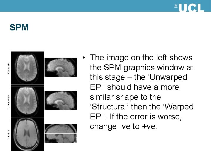
SPM • The image on the left shows the SPM graphics window at this stage – the ‘Unwarped EPI’ should have a more similar shape to the ‘Structural’ then the ‘Warped EPI’. If the error is worse, change -ve to +ve.
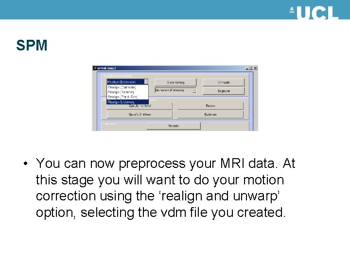
SPM • You can now preprocess your MRI data. At this stage you will want to do your motion correction using the ‘realign and unwarp’ option, selecting the vdm file you created.
Advantages and disadvantages • For ‘problematic’ brain regions the reduction of unwanted variance can be quite dramatic (>90%). • If movements are task related unwarping will remove unwanted variance without removing all your "true" activations. • Can be computationally intensive… so take a long time • Only deals with susceptibility-distortion-bymovement interaction problem
When should you do it? • If there is little movement in your data to begin with this method will do you no good. • If on the other hand there is appreciable movement in your data (>1 mm or >1 deg) it will remove some of that unwanted variance. • When you are focusing on problem areas (Frontal pole, orbito-frontal cortex, medial temporal lobe)
References and further reading Jezzard, P. and Clare, S. 1999. Sources of distortion in functional MRI data. Human Brain Mapping, 8: 80 -85 Andersson JLR, Hutton C, Ashburner J, Turner R, Friston K (2001) Modelling geometric deformations in EPI time series. Neuroimage 13: 903 -919 Previous years Mf. D slides. SPM website/ SPM manual