
Preparing Calibration Service Procedures and Validation Methods in
Preparing Calibration Service Procedures and Validation Methods in Support of CMCs Marina Gertsvolf Jan 28, 2014 2015 SIM TFWG Workshop
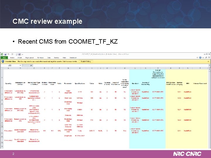
CMC review example • Recent CMS from COOMET_TF_KZ 2
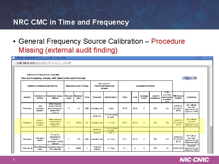
NRC CMC in Time and Frequency • General Frequency Source Calibration – Procedure Missing (external audit finding) 3
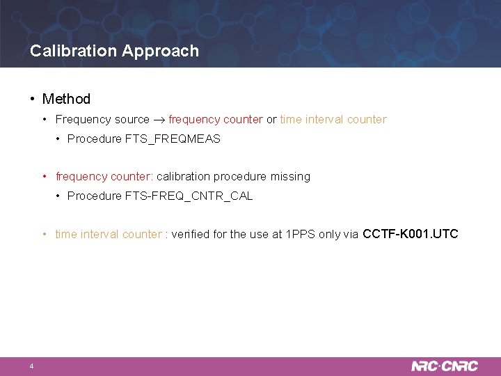
Calibration Approach • Method • Frequency source frequency counter or time interval counter • Procedure FTS_FREQMEAS • frequency counter: calibration procedure missing • Procedure FTS-FREQ_CNTR_CAL • time interval counter : verified for the use at 1 PPS only via CCTF-K 001. UTC 4
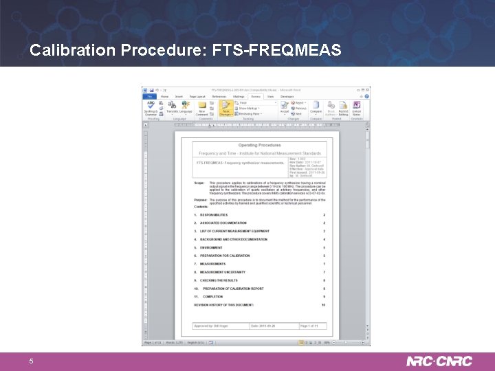
Calibration Procedure: FTS-FREQMEAS 5
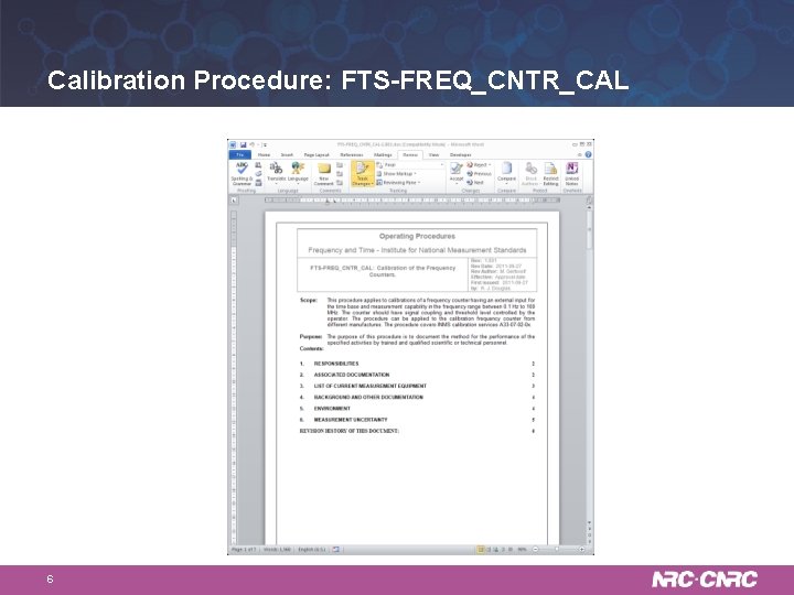
Calibration Procedure: FTS-FREQ_CNTR_CAL 6
Calibration Validation • Procedure: • Frequency source frequency counter or time interval counter • Validation: • Known frequency source Calibrated frequency counter or time interval counter • Over all frequency ranges and with the worst case slope • 100 ns rise time • 1 Vpp • 0. 1 Hz • 1 hr averaging 7
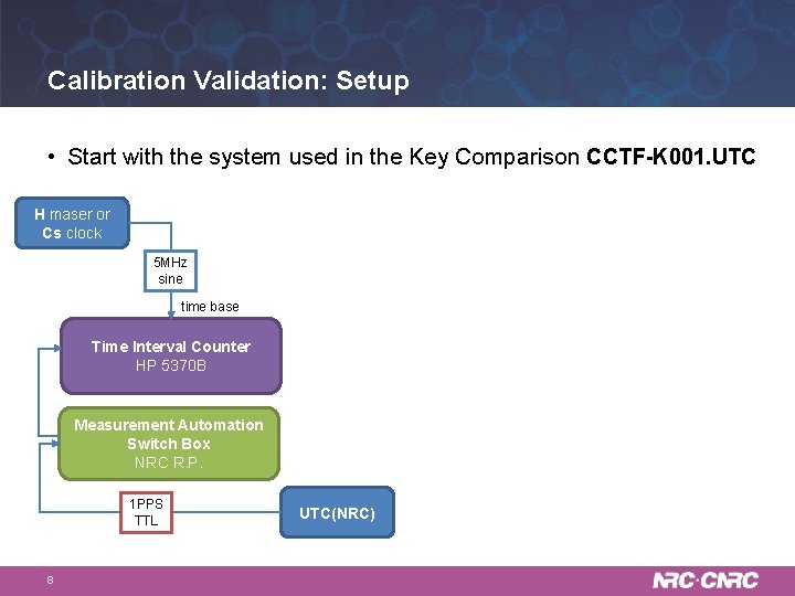
Calibration Validation: Setup • Start with the system used in the Key Comparison CCTF-K 001. UTC H maser or Cs clock 5 MHz sine time base Time Interval Counter HP 5370 B Measurement Automation Switch Box NRC R. P. 1 PPS TTL 8 UTC(NRC)
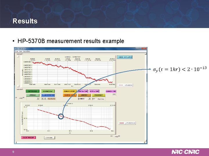
Results • HP-5370 B measurement results example 9
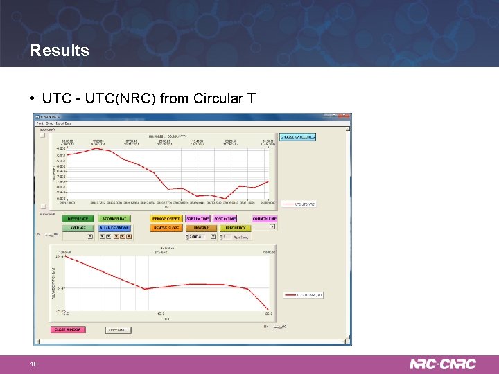
Results • UTC - UTC(NRC) from Circular T 10
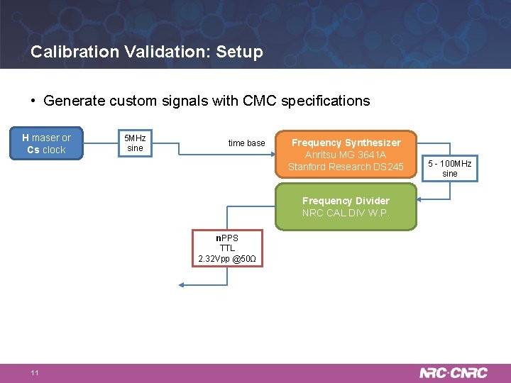
Calibration Validation: Setup • Generate custom signals with CMC specifications H maser or Cs clock 5 MHz sine time base Frequency Synthesizer Anritsu MG 3641 A Stanford Research DS 245 Frequency Divider NRC CAL DIV W. P. n. PPS TTL 2. 32 Vpp @50Ω 11 5 - 100 MHz sine
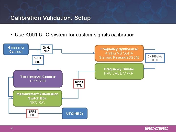
Calibration Validation: Setup • Use K 001. UTC system for custom signals calibration H maser or Cs clock 5 MHz sine Frequency Synthesizer Anritsu MG 3641 A Stanford Research DS 245 5 MHz sine Time Interval Counter HP 5370 B Frequency Divider NRC CAL DIV W. P. n. PPS TTL Measurement Automation Switch Box NRC R. P. 1 PPS TTL 12 UTC(NRC) 5 - 100 MHz sine
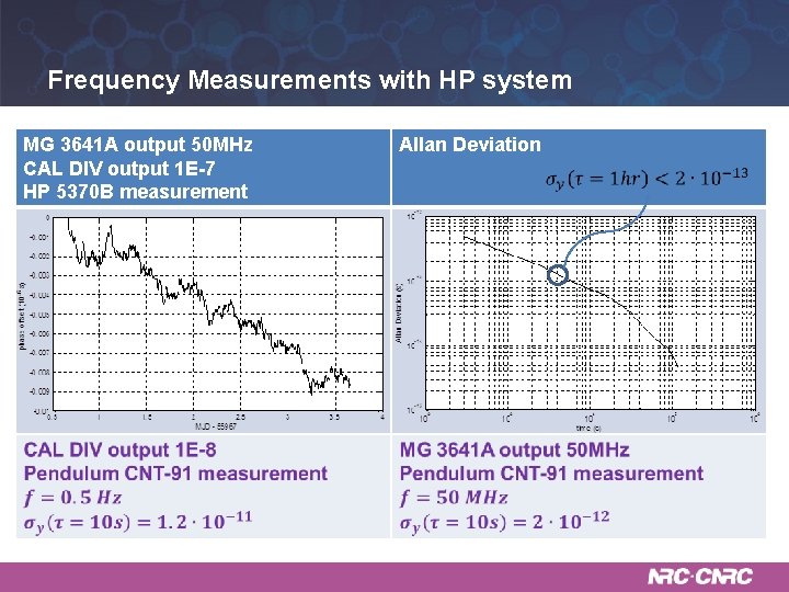
Frequency Measurements with HP system MG 3641 A output 50 MHz CAL DIV output 1 E-7 HP 5370 B measurement 13 Allan Deviation
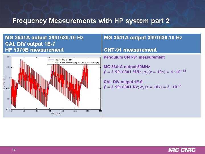
Frequency Measurements with HP system part 2 MG 3641 A output 3991680. 10 Hz CAL DIV output 1 E-7 HP 5370 B measurement 14 MG 3641 A output 3991680. 10 Hz CNT-91 measurement
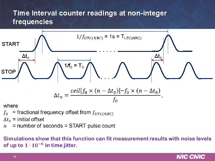
Time Interval counter readings at non-integer frequencies START Δtn STOP 15 Δt 0 1/f 0 = T 0
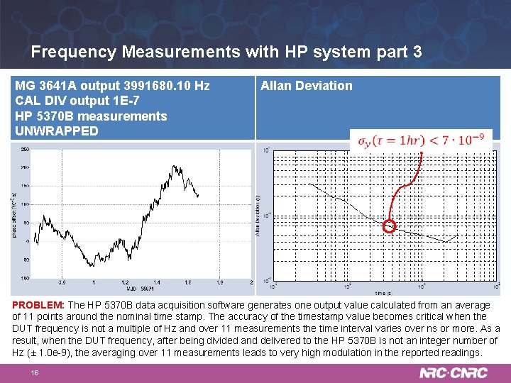
Frequency Measurements with HP system part 3 MG 3641 A output 3991680. 10 Hz CAL DIV output 1 E-7 HP 5370 B measurements UNWRAPPED Allan Deviation PROBLEM: The HP 5370 B data acquisition software generates one output value calculated from an average of 11 points around the nominal time stamp. The accuracy of the timestamp value becomes critical when the DUT frequency is not a multiple of Hz and over 11 measurements the time interval varies over ns or more. As a result, when the DUT frequency, after being divided and delivered to the HP 5370 B is not an integer number of Hz (± 1. 0 e-9), the averaging over 11 measurements leads to very high modulation in the reported readings. 16
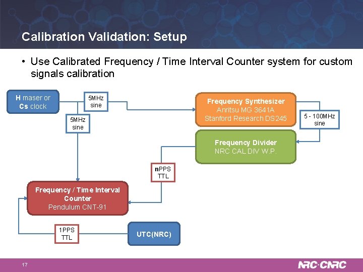
Calibration Validation: Setup • Use Calibrated Frequency / Time Interval Counter system for custom signals calibration H maser or Cs clock 5 MHz sine Frequency Synthesizer Anritsu MG 3641 A Stanford Research DS 245 5 MHz sine Frequency Divider NRC CAL DIV W. P. n. PPS TTL Frequency / Time Interval Counter Pendulum CNT-91 1 PPS TTL 17 UTC(NRC) 5 - 100 MHz sine
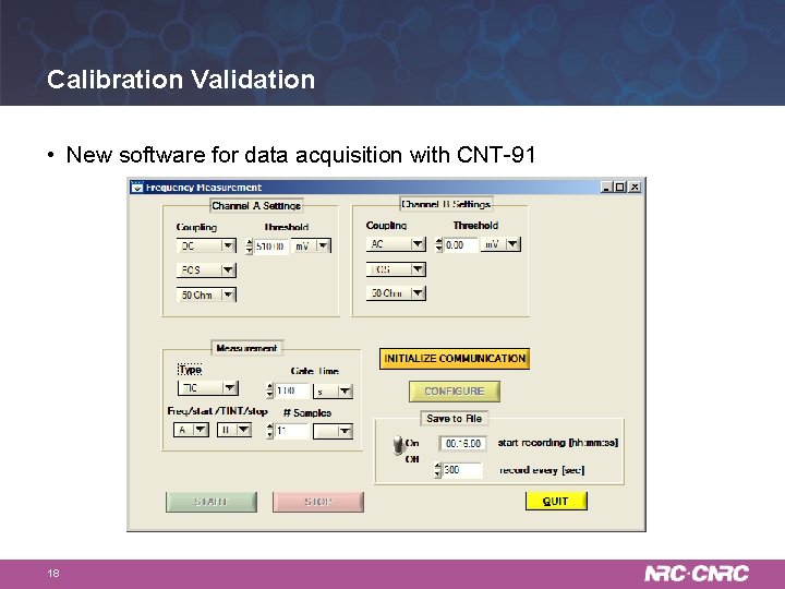
Calibration Validation • New software for data acquisition with CNT-91 18
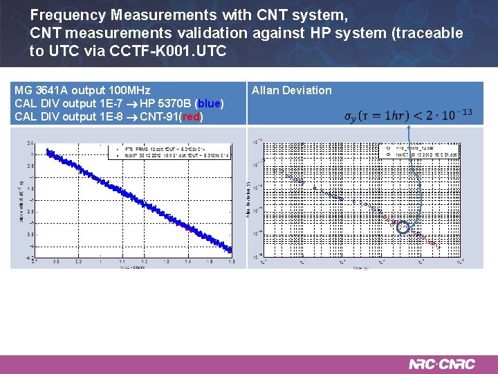
Frequency Measurements with CNT system, CNT measurements validation against HP system (traceable to UTC via CCTF-K 001. UTC MG 3641 A output 100 MHz CAL DIV output 1 E-7 HP 5370 B (blue) CAL DIV output 1 E-8 CNT-91(red) 19 Allan Deviation
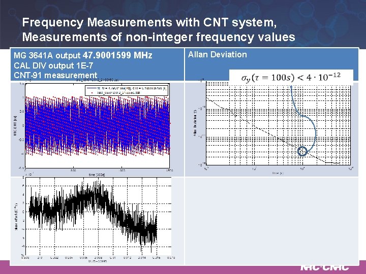
Frequency Measurements with CNT system, Measurements of non-integer frequency values MG 3641 A output 47. 9001599 MHz CAL DIV output 1 E-7 CNT-91 measurement 20 Allan Deviation
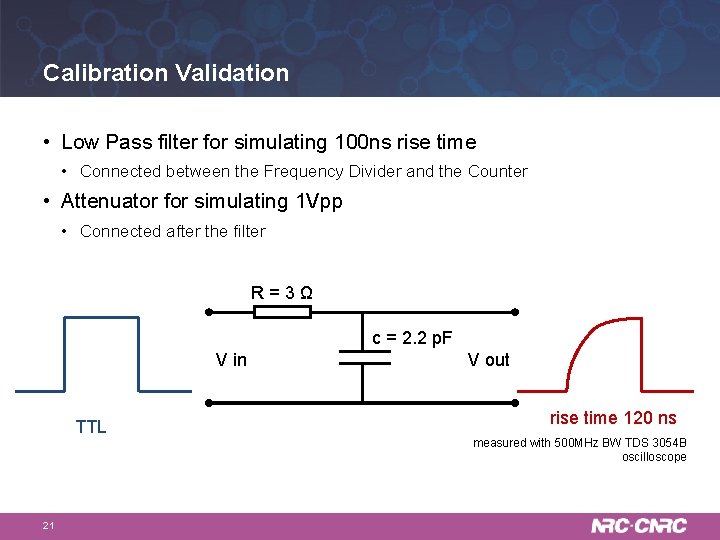
Calibration Validation • Low Pass filter for simulating 100 ns rise time • Connected between the Frequency Divider and the Counter • Attenuator for simulating 1 Vpp • Connected after the filter R = 3 Ω c = 2. 2 p. F V in TTL 21 V out rise time 120 ns measured with 500 MHz BW TDS 3054 B oscilloscope
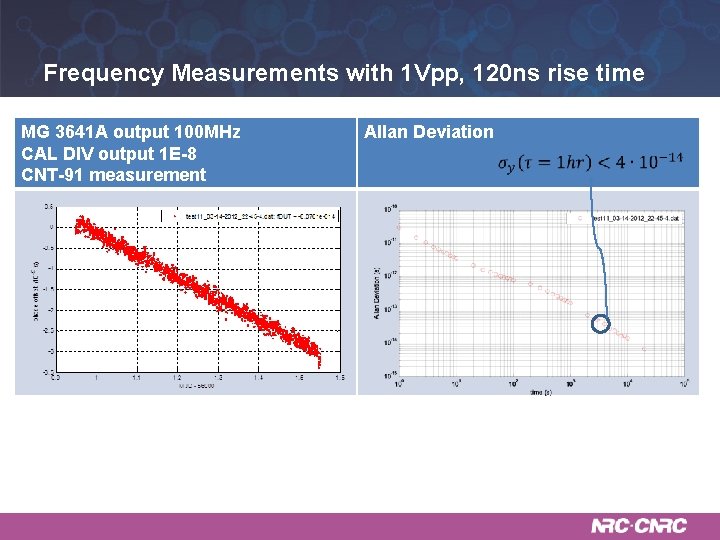
Frequency Measurements with 1 Vpp, 120 ns rise time MG 3641 A output 100 MHz CAL DIV output 1 E-8 CNT-91 measurement 22 Allan Deviation
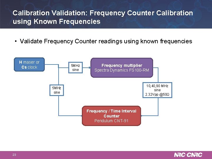
Calibration Validation: Frequency Counter Calibration using Known Frequencies • Validate Frequency Counter readings using known frequencies H maser or Cs clock 5 MHz sine Frequency multiplier Spectra Dynamics FS 100 -RM 10, 40, 90 MHz sine 2. 32 Vpp @50Ω 5 MHz sine Frequency / Time Interval Counter Pendulum CNT-91 23
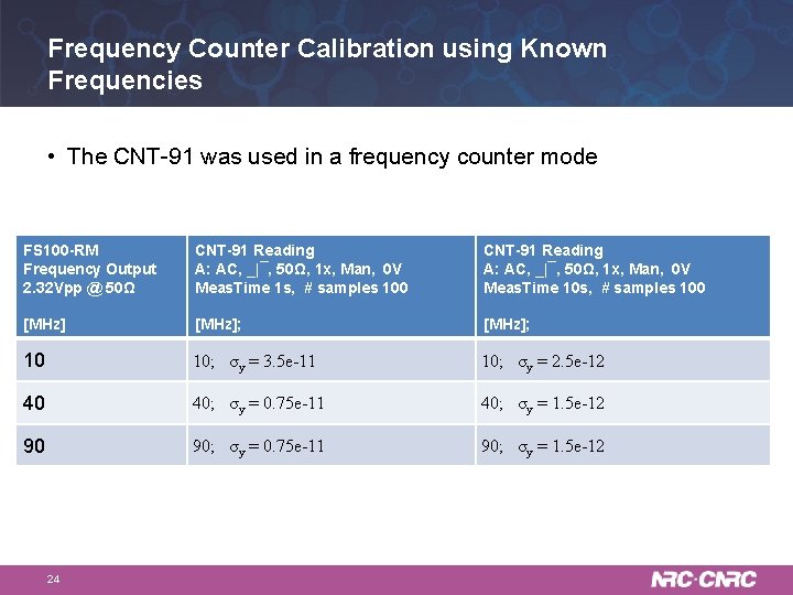
Frequency Counter Calibration using Known Frequencies • The CNT-91 was used in a frequency counter mode FS 100 -RM Frequency Output 2. 32 Vpp @ 50Ω CNT-91 Reading A: AC, _|¯, 50Ω, 1 x, Man, 0 V Meas. Time 1 s, # samples 100 CNT-91 Reading A: AC, _|¯, 50Ω, 1 x, Man, 0 V Meas. Time 10 s, # samples 100 [MHz]; 10 10; σy = 3. 5 e-11 10; σy = 2. 5 e-12 40 40; σy = 0. 75 e-11 40; σy = 1. 5 e-12 90 90; σy = 0. 75 e-11 90; σy = 1. 5 e-12 24
Summary • The validation had verified the measurement capability and the traceability to the levels exceeding CMC specifications • The frequency counter calibration procedure was developed and the counter was calibrated 25

Thank you Dr. Marina Gertsvolf Tel: 613 -998 -1311 marina. gertsvolf@nrc-cnrc. gc. ca www. nrc-cnrc. gc. ca 26
- Slides: 26