Prepared by Marimuthu Gurusamy Combined vibration analysis velocity
 for Prediction of")
Prepared by: Marimuthu Gurusamy Combined vibration analysis (velocity and acceleration envelope) for Prediction of rotating equipment (with rolling element bearings) and its component’s deterioration to determine the duration for maintenance

Velocity vibration analysis • How do we make decision whether we stop the machine or continue to run to meet the production requirement? • ISO 10816

Stop the machine based on Velocity readings Is it Correct? If not, Why?

Vibration Basic Back to vibration school

Vibration Basics Vibration Parameters Displacement Velocity Acceleration Vibration Amplitude Peak a Peak-Peak 2 a RMS 0. 707 a pk-pk peak/RMS peak microns/mils mm/sec or inch/sec m/sec 2 or g RMS a 2 a
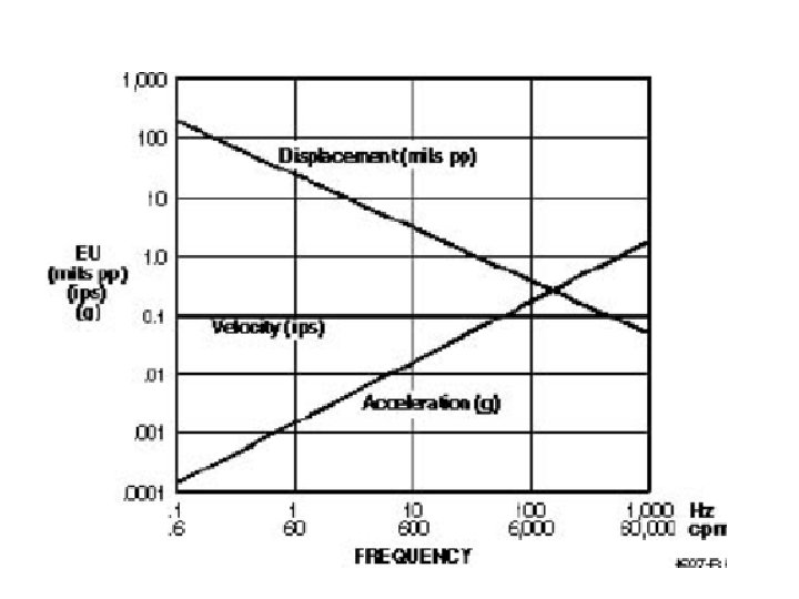

Amplitude Displacement frequency 1 khz 5 khz 10 khz 15 khz 20 khz Amplitude Velocity frequency Amplitude Acceleration frequency 1 khz 5 10 15 20

Rolling Element Bearing Structure Element Contact Angle, a a Outer Race Inner Race Pitch Diameter, D Axial Load Radial Load Rolling Element Bearing Under Simultaneous Radial and Axial Loading Elements Cage

Spectral Enveloping Process 6. Enveloping Step Amplitude 5. Signal Rectification Amplitude 4. Low Frequency Filtering 3. High Frequency Filtering Amplitude 2. Unfiltered Vibration Signal Amplitude 1. Periodic impact events • With each impact, the machine structure “rings” at its natural resonance frequency. • These impact events are embedded in a complex vibration signal, and are typically not detectable until they are extracted by the enveloping process.
 Level 1 : Define Severity (as")
Traditional Vibration Analysis Overall Vibration (Amplitude in peak/RMS/pk-pk) Level 1 : Define Severity (as per ISO 2372, 7910 & 10816) Frequency Level 2: (Hz, CPM & Orders) Define Source of Problem Phase (Degree) Level 3: Confirm Problem Can – Unbalance, Misalignment & Looseness Can not – Bearing, Gear, Impeller damage Envelope Level 2&3 Useful to analyse Problems in Rolling Element bearings.

Decisions making based on Velocity readings Is it Correct? If not, Why?

Case studies Challenges in monitoring velocity reading alone and how to interpretive combine analysis of Velocity and envelope spectrum.

Case-1 Low velocity high envelope-Level 1

Case-1 Low velocity high envelope-Level 1 velocity Envelope Bearing replaced

• Case 2 - Low velocity high envelope readings-Level 2

Case 2 - Low velocity high envelope readings-Level 2 Velocity Within acceptable limit Envelope in danger limit

Case Study 2 - Spectrum before bearing replacement Velocity Spectrum Envelope Spectrum

Case Study 2 - Spectrum - After bearing replacement Velocity Spectrum Envelope Spectrum

Case-3 - high velocity Low envelope Casing distortion-Level 2

velocity Envelope Case-3 - high velocity Low envelope Casing distortion-Level 2

Case-4 - Envelope relationship with unbalance-Level 2

Case-4 - Envelope relationship with unbalance. Level 2 Velocity Bearing replaced Fan cleaned Envelope

Conclusion • We seen 4 scenarios – Case 1 - Low velocity and high envelope reading Level 1 analysis – Case 2 - Low velocity and high envelope reading Level 2 analysis. – Case 3 – High velocity and Low envelope reading Level-2 analysis. – Case 4 - Envelope relationship with unbalance.

Key guide line in Envelope reading Analysis • Understand the envelope processing technically. Must use acceleration sensor for envelope readings. • Collect horizontal reading for envelope acceleration for radial bearing and axial direction for thrust bearings. Do not use top-vertical direction. • Always follow combine analysis with velocity spectrum and overall readings. • Use appropriate filters on collection of acceleration envelope readings. Use frequency filtering range as follows – 1. 1500 / 3000 rpm 500 Hz- 5 to 10 Khz – 2. General • 1. High Pass – 10 x rpm / HFFx 3 • 2. Low Pass – 5 to 10 KHz (depending on sensor mounting type)

Key guidelines in Envelope Spectrum Analysis • Do not correlate between normal spectrum analysis technique to envelope spectrum. Example like – 1 x amplitude is unbalance – 2 x amplitude as misalignment – Harmonics as looseness • Domination of 1 x amplitude alone as like unbalance symptom in normal spectrum, indicates severe bearing damage in one of the location in the raceways. • Domination of Bearing forcing frequencies like BPFI, BPFO, BSF and FTF will indicates directly related to the problem. • Harmonics of 1 x indicates that the high envelope readings are due to impact of mechanical problem like unbalance and misalignment. • Use waveform data analysis before make conclusion on super critical machines. • Use waveform interaction analysis where the gear problems are involved in the machine.

Key points to be considered in Envelope analysis • Always correlate envelope readings with velocity readings. • Increasing of envelope readings to 5 g considered for important attention on lubrication. If no reduction in envelope reading after lubrication, plan the spare , increase the monitoring frequency and watch till it reaches 10 g. • If no spare arrives and no plan for maintenance after reaching 10 g. Expedite the spare procurement process. • Do not allow the machine to run >25 g at any cost. From 10 g to 25 g is the duration for replacement of bearings, if velocity readings are normal. When velocity also abnormal plan the bearing replacement at 10 g itself.

Measuring Techniques used by different Manufacturers for Rolling Element Bearings 1. SPM - Shock Pulse Method (32 Khz) & Envelope 2. IRD - Spike Energy (30 Khz) & Envelope 3. SKF - SEE & Envelope 4. Csi - Peak View & Envelope 5. DLi - Cepstrum & Envelop 6. Bently- REBAM & Envelope 7. Others - (Commtest, Pruftechnik, ACOEM etc) Note: All above manufacturer instrument and software capable of data collection and analysis of envelope reading analysis for bearing failures.

Thanks you
- Slides: 28