PREPARED BY Darshan K Bhatt Asst Professor Mechanical

PREPARED BY, Darshan. K. Bhatt Asst. Professor Mechanical Engineering Department IITE, Ahmadabad

� INTRODUCTION � PATTERNS � MOULDING � CORE � METAL CASTING � METAL FURNACES � METALLURGICAL CONSIDERATION IN CASTING � CASTING DEFECTS

Manufacturing ? ? Raw material Manufacturing process Final product q Manufacturing processes coverts the raw material into finished products to be used for some purposes q A detail understanding of various Manufacturing Processes is essential for every engineer. q This helps in designing the proper product required for an Engineer.

Manufacturing Processes Metal Removal Metal Joining & Fabrication Metal Forming - Turning - Welding - Drawing - Milling - Brazing - Extrusion - Drilling - Soldering - Bending - Shaping - Adhesive Bonding - Rolling - Boring etc - Riveting -Fastening etc Metal Casting Metal Surface - Investment Treatments Casting - Centrifugal Casting etc Heat Treatments

Casting Forming Sheet metal processing Powder- and Ceramics Processing Plastics processing Cutting Joining Surface treatment

Raw material Manufacturing process Final product CASTING ? ? Casting q Conversion of a Liquid Material into a Solid of Some Useful Shape Through the Interaction with a Mold. q Introduction of molten metal into a mold cavity; upon solidification, metal conforms to the shape of the cavity. q The term casting is used to denote both the product and the process.

� Most suited for intricate shapes and for parts with internal cavities, such as engine blocks, cylinder heads, pump housing, crankshaft, machine tool beds and frames, etc. � Particularly suitable for small runs. � Cost of equipment and facilities low. � Some metals can be shaped by casting only because of the metallurgical and mechanical properties.
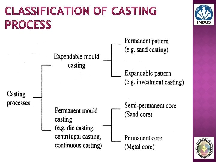

1. Expendable mold processes - mold is sacrificed to remove part. After use mould is destroyed. � Advantage: More complex shapes possible. � Disadvantage: Production rates often limited by time to make mold rather than casting itself. 2. Permanent mold processes - mold is made of metal and can be used to make many castings. � Advantage: Higher production rates. � Disadvantage: Geometries limited by need to open mold.
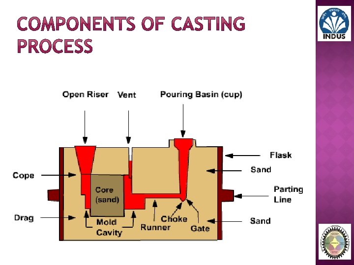
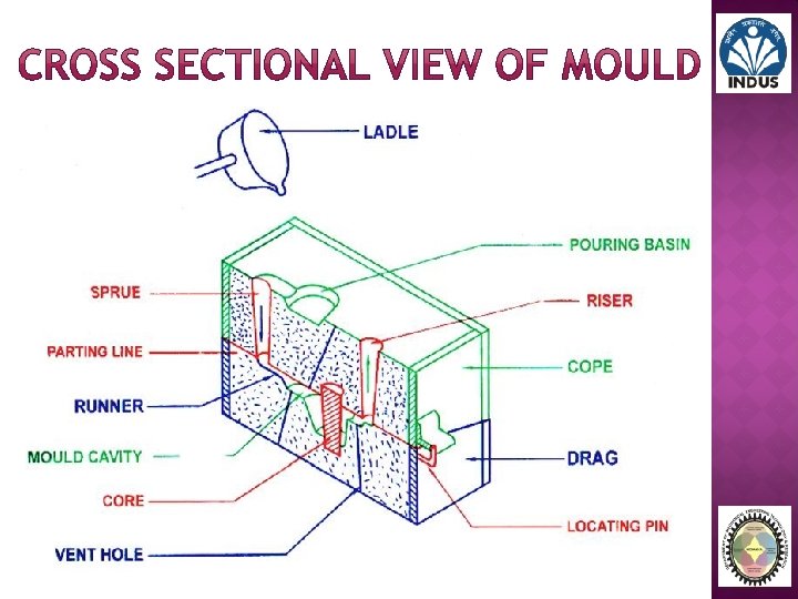

� Flask: A metal or wood frame, with out fixed top or bottom, in which mould is formed. Depending upon the position of flask in the molding structure, it is referred to by various names such as cope, drag and cheek. � Drag: Drag is the lower Molding Box. � Cope: Cope is the Upper Molding Box. � Check: Check is the intermediate Molding Box. � Pattern: Pattern is a replica of the desired final product with some modifications. The mould cavity is made with the help of the pattern. � Parting Line: Parting line is the dividing line between two or more molding boxes. In split pattern it also the dividing line between the two halves of the pattern.

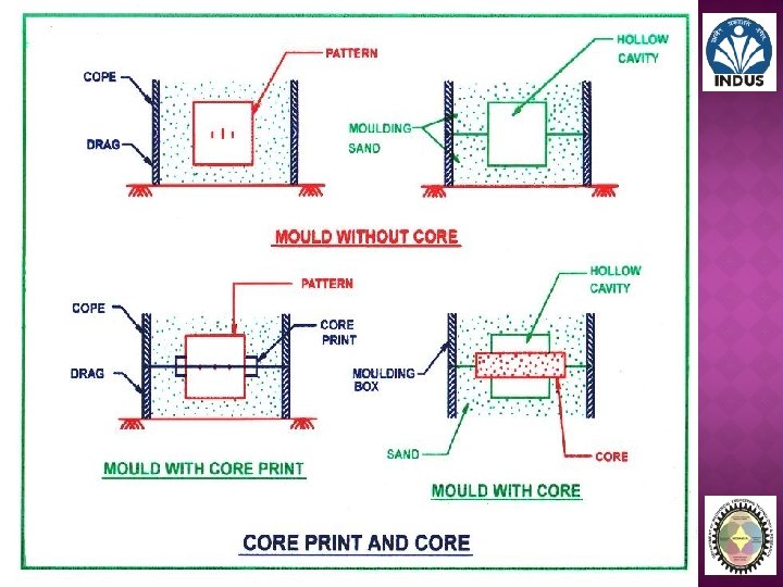
� Core: A separate part of the mould, made of sand generally baked, which is use to create opening and various shaped in the casting. � Core Print: Core print is provided in the pattern, core and mould to locate and support the core within the mould. � Pouring basin: A small funnel shaped cavity at the top of the mould into which the molten metal is poured. � Sprue: The passage through which the molten metal, from the pouring basin, reaches the mould cavity. In many cases it control the flow of metal into the mould. � Runner: The channel through which the molten metal is carried from the Sprue to the gate. � Riser: A column of molten metal is placed in the mould to feed the castings as it shrinks and solidified. Also known as feed head.

� Gate: A channel through which molten metal enters the mould cavity. � Chaplets: Chaplets are used to support the cores inside the mould cavity to take care of its own weight and overcomes the metallostastic force. � Vent: Small opening in the mould to facilitate escape of air and gases.

patterns

� Pattern is a replica of the desired final product with some modifications. � The mould cavity is made with the help of the patterns. � Patterns are slightly enlarged to account for shrinkage and machining allowances in the casting. � Patterns may be in two or three pieces, where castings are in single piece. � The quality of casting and a final product will be affected to a great extent by the planning of patterns.

� A patterns prepares a mould cavity for the purpose of making castings. � A pattern may contain projections known as core print if the casting requires a core and need to be made hollow. � Risers, runners and gates may form a part of the patterns. � Properly made patterns having finished and smooth surface to reduce casting defects. � Properly constructed patterns minimize overall cost of the castings.

The following factors assist in selecting proper pattern materials: � No of castings to be produces, � Metal to be cast, � Dimensional accuracy and surface finish, � Shape complexity and size of castings, � Casting design parameters, � Type of molding material, � Position of core print, � Nature of molding process.

The pattern material should be: � Easily worked, shaped and joint. � Light in weight � Strong, hard and durable. � Resistant to wear, abrasion, corrosion and chemical reaction. � Dimensionally stable and unaffected by variation in temperature and humidity. � Available at low cot.

� Wood � Metal � Plastic � Plaster � Wax

These are used where no. of castings to be produced is small and casting size is large. Advantage: � Inexpensive � Easily available in large quantity � Easy to fabricate � Light in weight � They can be repaired easily � Easy to obtain good surface finish.

Limitations: � Effected by shrinkage and swelling � Poor wear resistance � Absorb moisture and consequently get wrapped � Cannot withstand rough handling � Life is very short Commonly used woods for making pattern: � Pine � Teak � Mahogany � deodar

These are employed where large no. of castings have to be produced from the same pattern. Advantage: � Do not absorb moisture � More stronger � Posses much longer life � Do not wrap, retain their shape � Greater resistant to absorption � Accurate and smooth surface finish � Good machinability

Limitations: � Expensive � Require lots of machining for accuracy � Not easily repaired � Ferrous metal get rusted, and affected by corrosion � Heavy weight, thus difficult to handle Commonly used metals for making patterns: � Cast iron � Aluminum and its alloy � Steel � White metal � brass

Advantage: � Durable � Provide a smooth surface � Moisture resistant � Does not involve any change in size and shape � Light weight � Good strength � Wear and corrosion resistant � Easy to make � Abrasion resistant � Good resistant to chemical attack Limitations: � Plastic patterns are fragile. � These are may not worked well when subjected to conditions of severe shock as in machine molding (jointing).

Advantage: � Intricate shapes can be worked out easily. � It can be easily worked by using wood working tools. � It has high compressive strength. Plaster pattern may be made out by plaster of Paris or gypsum cement.

Wax pattern find applications in investment casting process. Advantage: � Provide good surface finish. � Impart high accuracy to casting. � After being molded, wax pattern is not taking out of the mould like other pattern. � Rather the mould is inverted and heated, the molten metal comes out and/or evaporated. � Thus there is no chances of mould cavity getting damaged.

TYPES OF PATTERNS

Types of patterns depends upon following factors: � The shape and size of casting. � No. of castings required. � Methods of molding employed. � Anticipated operations. difficulty of molding

1. Single piece pattern 2. Split piece pattern 3. Loose piece pattern 4. Match plate pattern 5. Sweep pattern 6. Gated pattern 7. Skeleton pattern 8. Cope and drag pattern

� Made from one piece and does not contain joints. � Inexpensive � Used for large size simple casting � Pattern is accommodated in either cope or drag. Examples: 1. Stuffing box of steam engine 2. Bodies of regular shapes

Fig: single piece pattern

� Patterns of intricate shaped casting cannot be made one piece because of the inherent difficulties associated with the molding operations. (e. g. withdrawing pattern from the mould). � The upper and lower part of the split piece pattern are accommodated in the cope and drag portion of the mould respectively. � Parting line of the pattern forms a parting line of the mould. � Dowel pins are used for keeping alignment between the two part of the pattern. Examples: 1. Hallow cylinder 2. Tapes and water stop cocks etc.

Fig: Split piece pattern

� Certain patterns cannot be withdrawn once they are embedded in the molding sand. Such patterns are usually made with one or more loose pieces for facilitating from the mould box and are known as loose piece pattern. � Loose parts and piece remain attached with the main body of the pattern, with the help of the dowel pins. � The main body of the pattern is drawn first from the molding box and thereafter as soon as the loose parts are removed, the results is the mould cavity.

Fig: Loose piece pattern

� It consist of a match plate, on the either side of which each half of split pattern is fastened. � A no. of different sized and shaped patterns may be mounted on the match plate. � The match plate with the help of locator holes can be clamped with the drag. � After the cope and drag have been rammed with the moulding sand, the match plate pattern is removed from in between the cope and drag. � Match plate pattern is normally used in machine moulding. � By using this we can eliminate mismatch of the cope and the drag cavities.

Fig: Match plate pattern

� A sweep pattern is just a form made on a wooden board which sweep the shape of casting into the sand all around the circumference. The sweep pattern rotates about the post. � Once the mould is ready, sweep pattern and the post is removed. � Sweep pattern avoid the necessity of making of full, large circular and costly three dimensional pattern. � Making a sweep pattern save a lot of time and labor as compare to making a full pattern. � Sweep patterns are preferred for producing a large casting of circular section and symmetrical shapes.

Fig: Sweep pattern

� The sections connecting different patterns serve as runner and gates. � This facilitates filling of the moulds with molten metal in a better manner and at the same time eliminates the time and labor otherwise consumed in cutting runner and gates. � A gated pattern can manufacture many castings at one time and thus it is used in mass production system. � Gated patterns are employed for producing small castings.

Fig: Gated pattern

Fig: Gated pattern

� A skeleton pattern is the skeleton of the desired shape which may be S-band pipe or some thing else. � The skeleton frame is mounted on a metal base. � The skeleton is generally made up of wooden strips. � The skeleton pattern is filed with the sand is rammed. � Skeleton pattern is employed for producing a large castings. � Skeleton pattern is economical, because it involves less material costs.

Fig: Skeleton pattern

� A cope and drag is another form of split pattern. � Each half of the pattern is fixed to a separate metal/wood plate. � Each half of the pattern (along the plate) is moulded separately in a separate moulding box by an independent molder. � The two moulds of the each half of the pattern are finally assembled and the mould is ready for pouring. � Cope and drag patterns are used for producing big castings which as a whole cannot be conventionally handled by one molder alone.

Fig: Cope and drag pattern

Pattern allowances

A pattern is larger in size as compared to the final castings, because it carries certain allowances due to metallurgical and mechanical reasons for example, shrinkage allowances is result of metallurgical phenomenon where as machining, draft, distortion, shake and other allowances are provided on pattern because of mechanical reasons.

1. Shrinkage or contraction allowances 2. Machining or finish allowances 3. Draft or taper allowances 4. Distortion or chamber allowances 5. Shake or rapping allowances

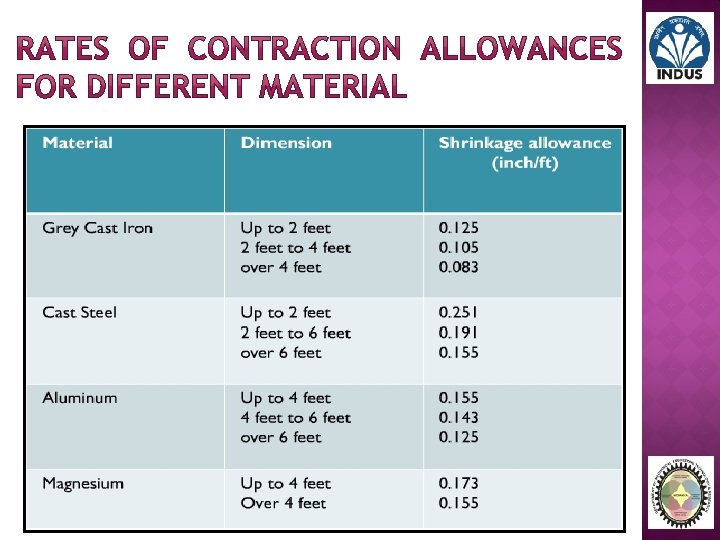
All most all cast metals shrink or contract volumetrically on cooling. The metal shrinkage are of two types: 1. Liquid shrinkage: It refers to the reduction in volume when metal changes from liquid state to solid state at solidus temperature. To account for this shrinkage; riser which feed the liquid metal to the casting are provided in the mould. 2. Solid shrinkage: It refers to the reduction in volume cause metal loses temperature in solid state.

� Almost all cast metal shrink or contract volumetrically after solidification and therefore a pattern to obtain a particular sized casting is made oversize by an amount equal to that of shrinkage or contraction. � Different metal shrink at different rates because shrinkage is a property of cast metal/alloy. � The metal shrinkage depends upon: I. The cast metal/alloy. II. Pouring temperature of the metal/alloy. III. Casted dimensions(size). IV. Casting design aspects. V. Moulding conditions (i. e. moulding methods employed). materials and

� The metals/alloys is always volumetric, but the contraction allowance are always expressed in linear measure.

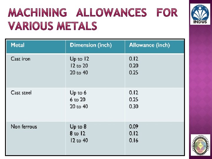
A casting is given an allowance for machining because: � Castings get oxidized in the mould during heat treatment, scales; etc. thus formed need to be removed. � It is intended to remove surface roughness and other imperfections from the casting. � It is required to achieve exact casting dimensions. � Surface finish is required on the casting.

How much extra metal or how much machining allowances should be provided, depends on the factors listed below; i. Nature of metal ii. Size and shape of casting. iii. The type of machining operations to be employed for the cleaning of casting.

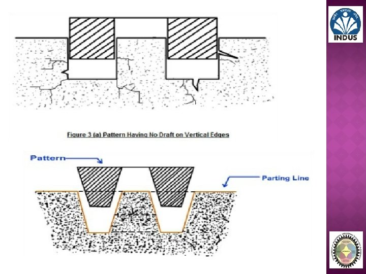
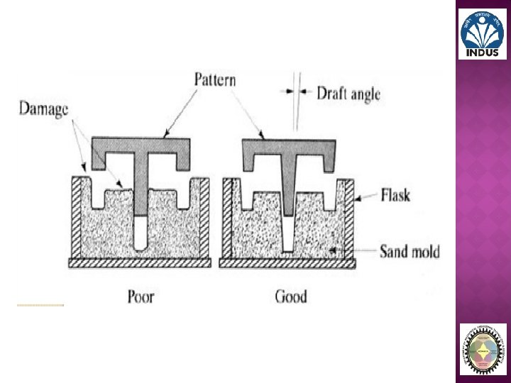
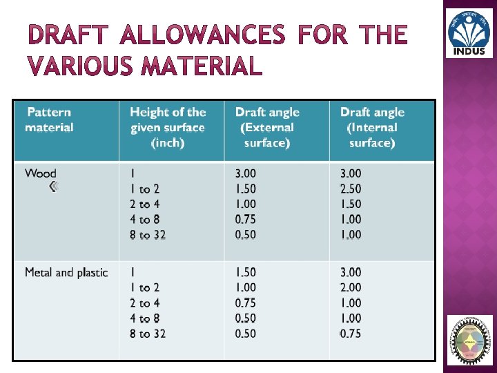
� It is given to all surfaces perpendicular to parting line. � Draft allowance is given so that the pattern can be easily removed from the moulding material tightly packed around it without damaging the mould cavity. The amount of tapper depends upon: i. Shape and size of the pattern in the depth direction in the contact with the mould cavity. ii. Moulding methods iii. Mould materials iv. Draft allowances is imparted on the internal as well as external surface; of course it is more on internal surface.

A casting will distort if; � It is of irregular shape. � All it part do not shrink uniformly i. e. some parts shrinks while others are restricted from during so. � It is U and V shape. � It is a long flat casting.
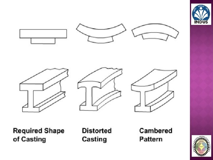
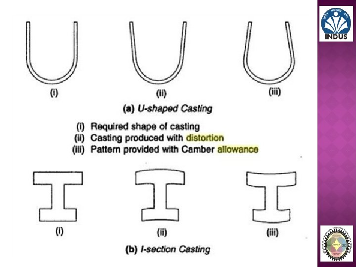

� A pattern is shaken and rapped by striking same with a wooden piece from side to side. This is done so that the pattern a little is loosened in the mould cavity and can be easily removed. � Therefore shaking or rapping enlarge the mould cavity which result in a bigger size casting. � Hence, a -ve allowance is given to the pattern i. e. , pattern dimensions are kept smaller In order to compensate the enlargement of mould cavity due to rapping. � The magnitude of shake allowance can be reduced by increasing the tapper.

Pattern layout And Pattern construction

Steps involved: � Get the working drawing of the part for which pattern is to be made. � Make two view of the part drawing on a sheet, using shrink rule. A shrink rule is a modified form of an ordinary scale which has already taken care of shrinkage allowance for the particular metal to be cast. � Add machining allowances as per requirement. � Depending upon the method of the moulding, provide the draft allowances.

� � Study the pattern layout carefully and established; a. Location of parting surface b. No. of parts in which the pattern will be made. Using the various hand tools and pattern making machines fabricate the different parts of the pattern. � Inspect the pattern as regards the alignment of different portion of the pattern and its dimensional accuracy. � fill wax in all the fillets to remove sharp corners. � Give shellac coating to all the patterns. � Impart suitable colors to the pattern for identification purpose and for other information.

Patterns are imparted certain colors and shades in order to: � Identify quickly pattern and main body of the different parts of the pattern. � Indicate the type of metal to be cast. � Identify core print, loose piece easily. � Visualize surfaces to be machined, etc.

The pattern are normally painted with color so the mould maker would be able to understand the functions clearly. � Red or Orange on surfaces not to be finished and left as cast. � Yellow on surfaces to be Machined. � Black on core prints for un-machined operation. � Green on seats of and for loose pieces and loose core prints. � Diagonal Black strips with clear varnish on stop-offs to strengthen the weak patterns or to shorten a casting.

MOULD PREPARATION
 � Properties of")
Mould preparation is depends upon; � Types of molding material (sand) � Properties of molding material � Composition of Molding material � Mould box considerations � Molding methods � Casting material � Types of patterns

Major part of molding material in sand casting are � 70 -85% silica sand (Sio 2) � 10 -12% bonding material. E. g. , clay, cereal etc. � 3 -6% water Requirement of molding sand are, § Refractoriness § Cohesiveness § Permeability § Collapsibility § Green strength § Dry strength § Hot strength § Flowability § Adhesiveness § Fineness

�A large variety of molding material is used in foundries for manufacturing moulds and cores. They include molding sand, and baking sand, facing sand, parting sand core sand. The choice of molding material is based on their processing properties. The properties that are generally required in molding material are;

� It is the ability of the moulding material to withstand high temperature (experience during pouring) without § Fusion § Cracking § Experiences any major physical change § Silica sand has high refractoriness

� Why required good permeability in molding material � Because to remove vapor which is generated when moisture from molding sand is vaporized when it comes in a contact with molten metal (high temperature). � During pouring and subsequent solidification of a casting, a large amount of gases and steam is generated. � If these gases are not allowed to escape from the mould, they would be entrapped in the casting and cause casting defects. � To overcome this problem the molding material must be porous.

� The molding sand that contains moisture is termed as green strength. � The green sand particle must have the ability to cling to each other to impart sufficient strength to mould. � The green sand must have enough strength so that constructed mould retain their shape. � Green strength helps handling of the mould. in making and

� A mould may either intentionally be dried, or green sand may loose its moisture and it get dried while waiting for getting poured or when it comes in a contact with molten metal being poured. � The sand thus dried must have dry strength to, § Withstand erosive force due to molten metal. § Withstand pressure of molten metal. § Retain its exact shape. § Withstand metallostastic pressure of molten metal.

� As soon as the moisture is eliminated, the sand would reach at high temperature when the metal in the mould is still in liquid state. � The strength of the sand that is required to hold the shape of the cavity is called hot strength. � In the absence of adequate hot strength, the mould may, § Enlarge § Break, erode or § Get cracked

� Collapsibility determines the readiness with which molding sand, � Automatically gets collapsed after the casting solidifies. � Break down in knock out and cleaning operations. � If the mould and cores does not collapsed, it may restrict free contraction or solidifying metal and cause the same to tear and crack.

� It is the ability of the molding sand to get compacted to a uniform density. � Flowability assist molding sand to flow and pack all around pattern and take up the required shape. � Flowability increase as the clay and water content increase.

� It is the property of the molding sand owning to which it, § Sticks with the walls of the molding box. § Sticks with the successive grains of the molding sand § Thus it possible to mold cope and drag.

� Finer sand mold resist metal penetration and produce smooth casting surface. � Fineness and permeability are in conflict with each other and hence they must be balanced for optimum value.

The main ingredient of any molding sans are; � Base sand � Binder � moisture

Molding sand can be of two types; � Natural sand: A sand which is available with certain amount of clay and water. � Synthetic sand: A sand which is prepared from base sand essentially free from clay.

� This sand contain base sand which can be lake or river sand with very low clay content or specially washed silica sand. � Silica sand is most commonly used base sand. � Other base sand that are also used for making mold are Zircon sand, Chromite sand Olivine sand. � Silica sand is cheapest among all types of base sand it is easily available. � But due to impurities present in them, are generally less refractory then synthetic sand. � They are suitable for making moulds for non-ferrous and gray cast iron castings.

� For molding in steel foundries, a highly refractory sand is required due to higher pouring temperature of steel (1600 - 1700ºC). � Synthetic sands are therefore invariably used in steel foundries. � It is easier to control the properties of synthetic sand then those of natural sand.

In different sands, these sand particles may differ in the following way; � Average grain size � Grain size distribution � Grain shape � Chemical composition � Refractoriness and thermal stability
, 99. 8% is considered the most")
� Generally the purest silica sand (Si 02), 99. 8% is considered the most refractory and thermally stable. Reference: New Jersey Silica Sand Co.

� The presence of accretive amount of iron oxide, alkali oxide and lime can cause objectionable lowering of fusion point in sand. � Average fineness of the sand grains established the fineness of molding sand as a whole. � Grain size distribution affects many of the sand properties. � The shape of sand grain may be rounded, angular or sub angular depending on their geological history.

Rounded Angular Compoun d Sub angular

Binders are of many types such as, � � � Clay Binders 1. Bentonites (Montmorillonites) 2. Fire clay (Kaolinites) 3. Special clay (Halloysite, Illite and Attuapulgite) Organic Binders 1. Cereals 2. Resin and Gums 3. Proteins 4. Pitch 5. Drying oil Inorganic Binders 1. Portland cement (Ordinary construction cement) 2. Sodium silicate 3. Water glass

� Clay binders are most commonly used binding agents mixed with the molding sands to provide the strength. � Clay also provide plasticity to the molding sand. � In clay compound some minerals are deposits and then it is mixed with the sand in proper proportions. � This sand mixture can be directly used for molding. Some of the clay are; � Western and Southern bentonites (Montmorillonites) (Al 203 4 Si 02 n. H 20) � Fire clay (Kaolinites) (Al 203 2 Si 02 2 H 20) � Special clay (Halloysite, Illite and Attuapulgite) � The first two types are the most commonly used.

� � Cereal: § These binders are, grains of wheat, corn and molasses fluids. § They impart good flowability and collapsibility for core sand. § Sands with these binders are baked at 190ºC to develop strength. § They cannot be stored for a long time. Resins and Gums: § Resins are mostly synthetic while gums are tree or petroleum products. § They develop high strength. § They are quite expensive.

� � Protein binders: § These are essentially made of milk protein. § They impart good surface finish. Pitch: § Pitch is a coal-tar residues. § It is, water resistance, strong and hard. § This evolves large amount of gasses when metal is poured into the mould. � Drying oil: § These are linseed oil, soybean oil and fish oil. § These are used specially for core sand.

� Water, present in amount of about 1. 5 to 8 percent. � Water in the molding sand is often referred to as ‘Tempering water’. � when water is added to clay, it penetrate in the mixture and form a microfilm, which coats the surface of each flake of the clay. � That water rigidly held (absorbed) by the clay appears to be effective in developing strength. � Additional water, however can act as a lubricant, and makes the mould more plastic and moldable. Which may be reduce the strength. � Thus control of water percentage in the aggregate is very important.

� Besides the three basic ingredients, other material may be present in the molding sands. � They are often referred to as additives and are use to develop some specific property. § Cereals § Ground pitch § Asphalt § Sea coal § Graphite § Gilsonite § Fuel oil § Wood flour § Silica flour § Iron oxide § Partite

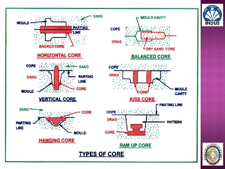
TYPES OF CORE AND CORE PRINT

� For metal castings with internal geometry cores are used. � A core is a replica, of the internal features of the part to be cast. � Like a pattern the size of the core is designed to accommodate for shrinkage during the metal casting operation, and machine allowance. � Core is usually made of a similar material as the mold. � Once the metal casting has hardened the core is broken up and removed much like the mold. � Structural supports that hold the core in place are called chaplets. � The chaplets are made of a material with a higher melting temperature than the casting's material

� The core is placed in the metal casting after the removal of the pattern.
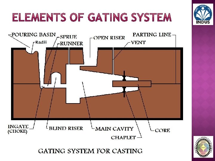

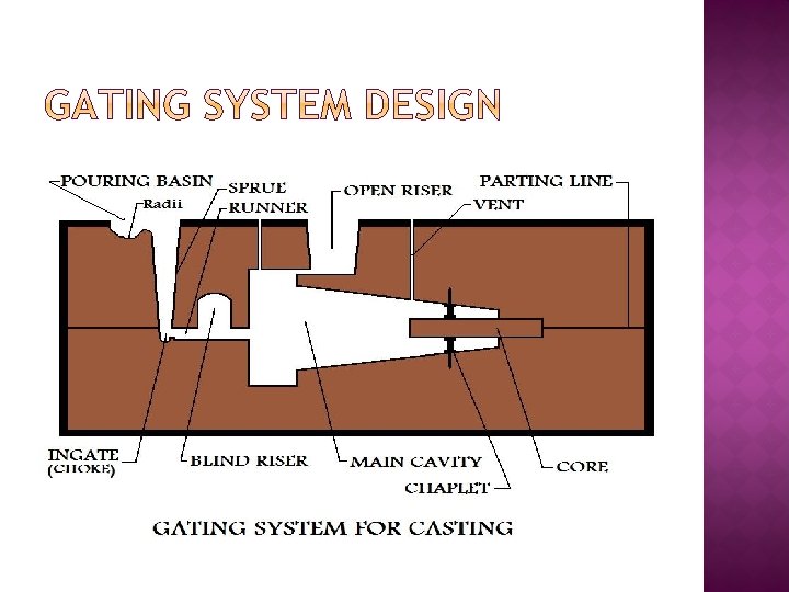
� Pouring Basin: This is where the molten metal employed to manufacture the part enters the mold. The pouring basin should have a projection with a radius around it to reduce turbulence. � Down Sprue: From the pouring basin the molten metal for the casting travels through the down Sprue. This should be tapered so its cross-section is reduced as it goes downward. � Sprue Base: The down Sprue ends at the Sprue base. It is here that the casting's inner cavity begins. � Ingate/Choke Area: Once at the Sprue base the molten material must pass through the ingate in order to enter the inner area of the mold. The ingate is very important in flow regulation during the metal casting operation.

� Runners: Runners are passages that distribute the liquid metal to the different areas inside the mold. � Main Cavity: The impression of the actual part to be cast is often referred to as the main cavity. � Vents: Vents help to assist in the escape of gases that are expelled from the molten metal during the solidification phase of the metal casting process. � Risers: Risers are reservoirs of molten material. They feed this material to sections of the mold to compensate for shrinkage as the casting solidifies. There are different classifications for risers. Top Risers: Risers that feed the metal casting from the top. Side Risers: Risers that feed the metal casting from the side. Blind Risers: Risers that are completely contained within the mold. Open Risers: Risers that are open at the top to the outside environment.

Bellow Rammer Lifter

Slick Mold box Shovel

Ladle Crucible Riddle

TYPES OF MOLDING PROCESS

Green-Sand Molds: � A green sand mold is very typical in casting manufacture, it is simple and easy to make, a mixture of sand, clay and water. The term green refers to the fact that the mold will contain moisture during the pouring of the casting. Manufacturing Considerations and Properties of Green-Sand Molds: � Possess sufficient strength for most casting applications � Good collapsibility � Good permeability � Good reusability � Least expensive of the molds used in sand casting manufacturing processes � Moisture in sand can cause defects in some castings, -dependent upon the type of metal used in the sand casting and the geometry of the part to be cast.

Dry-Sand Molds: � Dry-Sand molds are baked in an oven, (at 300 F - 650 F for 8 -48 hours), prior to the casting operation, in order to dry the mold. This drying strengthens the mold, and hardens its internal surfaces. Dry-Sand molds are manufactured using organic binders rather than clay. Manufacturing Considerations and Properties of Dry-Sand Molds: � Better dimensional accuracy of cast part than green-sand molds � Better surface finish of cast part than green-sand molds � More expensive manufacturing process than green-sand production � Manufacturing production rate of castings are reduced due to drying time � Distortion of the mold is greater � The metal casting is more susceptible to hot tearing because of the lower collapsibility of the mold � Dry-Sand casting is generally limited to the manufacture of medium and large castings.

Skin-Dried Molds: � When sand casting a part by the skin-dried mold process a green-sand mold is employed, and its mold cavity surface is dried to a depth of. 5 1 inch. Drying is a part of the manufacturing process and is accomplished by use of torches, heating lamps or some other means, such as drying it in air. Manufacturing Considerations and Properties of Skin-Dried Molds: � The cast part dimensional and surface finish advantages of dry-sand molds are partially achieved � No large oven is needed � Special bonding materials must be added to the sand mixture to strengthen the mold cavity surface

� Shell mold casting is a semi precise method for producing small casting respectively in large numbers. � Casting process in which the mold is a thin shell of sand held together by thermosetting resin binder. � The mould material contains Phenolic resin mixed with fine dry silica. � These are mixed either dry or in the presence of alcohol; no water is used. � Normally, a machined pattern of gray cast iron, aluminums or brass is used in this process.
 A match plate or cope and drag metal pattern is heated to 230")
(1) A match plate or cope and drag metal pattern is heated to 230 -260º C and placed over a box containing sand mixed with thermosetting resin.
 box is inverted so that sand resin fall onto the hot pattern, causing")
(2) box is inverted so that sand resin fall onto the hot pattern, causing a layer of the mixture to partially cure on the surface to form a hard shell up to 23 -30 sec. (3) box is repositioned so that loose uncured particles drop away and a layer of sand adheres to pattern in form of shell of about 6 mm thickness. q The thickness can be controlled by dwell time.
 sand shell is heated in oven (at 300ºC) for several minutes to complete")
(4) sand shell is heated in oven (at 300ºC) for several minutes to complete curing (5) shell mold is stripped from the pattern by ejector pin.
 two halves of the shell mold are assembled, supported by sand or metal")
(6) two halves of the shell mold are assembled, supported by sand or metal shot in a box, and pouring is accomplished (7) the finished casting with Sprue removed.

Advantages of shell molding: q Smoother cavity surface permits easier flow of molten metal and better surface finish q Good dimensional accuracy - machining often not required q Less cracks in casting Disadvantages: q Takes more time q Because of resin, more expensive q Shell not reusable

Uses a mold of sand packed around a polystyrene foam pattern which vaporizes when molten metal is poured into mold � Other names: lost foam process, lost pattern process, evaporative foam process, and full mold process � Polystyrene foam pattern includes Sprue, risers, gating system, and internal cores (if needed) Mold does not have to be opened into cope and drag sections
 pattern of polystyrene is coated with refractory compound")
Expanded polystyrene casting process: (1) pattern of polystyrene is coated with refractory compound
 foam pattern is placed in mold box, and sand is compacted around the")
(2) foam pattern is placed in mold box, and sand is compacted around the pattern
 molten metal is poured into the portion of the pattern that forms the")
(3) molten metal is poured into the portion of the pattern that forms the pouring cup and Sprue. As the metal enters the mold, the polystyrene foam is vaporized ahead of the advancing liquid, thus the resulting mold cavity is filled.

� � Advantages of expanded polystyrene process: q Pattern need not be removed from the mold q Faster: two mold halves are not required Disadvantages: q. A new pattern is needed for every casting q Cost is highly dependent on cost of producing patterns

A pattern made of wax is coated with a refractory material to make mold, after which wax is melted away prior to pouring molten metal � "Investment" comes from a less familiar definition of "invest" - "to cover completely, " which refers to coating of refractory material around wax pattern � It is a precision casting process - capable of producing castings of high accuracy and intricate detail
 wax patterns are produced, (2) several patterns are attached")
Steps in investment casting: (1) wax patterns are produced, (2) several patterns are attached to a sprue to form a pattern tree
 the pattern tree is coated with a thin layer of refractory material, (4)")
(3) the pattern tree is coated with a thin layer of refractory material, (4) the full mold is formed by covering the coated tree with sufficient refractory material to make it rigid
 the mold is held in an inverted position and heated to melt the")
(5) the mold is held in an inverted position and heated to melt the wax and permit it to drip out of the cavity, (6) the mold is preheated to a high temperature, the molten metal is poured, and it solidifies
 the mold is broken away from the finished casting and the parts are")
(7) the mold is broken away from the finished casting and the parts are separated from the Sprue

� Advantages of investment casting: q Parts of great complexity and intricacy can be cast q Close dimensional control and good surface finish q Wax can usually be recovered for reuse q Additional machining is not normally required ‑ this is a net shape process � Disadvantages q Many processing steps are required q Relatively expensive process

� Economic disadvantage of expendable mold casting: a new mold is required for every casting � In permanent mold casting, the mold is reused many times The processes include: � Basic permanent mold casting � Die casting � Centrifugal casting

� Uses a metal mold constructed of two sections designed for easy, precise opening and closing � Molds used for casting are commonly made of steel or cast iron � Molds used for casting steel must be made of refractory material, due to the very high pouring temperatures Mold metal must have higher melt temperature than casting metal
 mold is preheated and coated")
Steps in permanent mold casting: (1) mold is preheated and coated
 cores (if used) are inserted and mold is closed (3) molten metal is")
(2) cores (if used) are inserted and mold is closed (3) molten metal is poured into the mold, where it solidifies.

� Advantages of permanent mold casting: � Good dimensional control and surface finish � More rapid solidification caused by the cold metal mold results in a finer grain structure, so castings are stronger � Limitations: � Generally limited to metals of lower melting point � Simpler part geometries compared to sand casting because of need to open the mold � High cost of mold

� A permanent mold casting process in which molten metal is injected into mold cavity under high pressure � Pressure is maintained during solidification, then mold is opened and part is removed � Molds in this casting operation are called dies; � Use of high pressure to force metal into die cavity is what distinguishes this from other permanent mold processes � Tungsten and molybdenum dies used to die cast steel and cast iron

� The dies are usually made in to two parts which must be locked before molten metal is forced into them under high pressure of 7 to 700 MPa. The pressure may be obtained by the application of compressed air or by hydraulically operated piston. � The ferrous metals are not die-casted because temperature. Two types of die casting machines used for die casting. � 1. Hot chamber die casting Machine. � 2. Cold Chamber die casting Machine. of high pouring

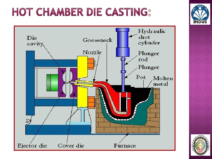
� The hot chamber die casting machine of the submerged type. The molten metal is forced in to the die cavity at pressure from 7 to 14 MPa � The pressure may be obtained by compressed air or by hydraulically operated plunger. � In first method the goose neck is lowered into the molten metal for filling it. It is then raised and connected to the die neck. The compressed air at a pressure of about 2. 5 to 5 MPa is now injected into goose neck to force the molten metal into the die. � In the second method the plunger acts inside cylinder formed at the end of the goose neck which is immersed in a pot of molten metal. A port is provided near the top of the cylinder to allow the entry of the molten metal. The downward stroke of the plunger pushes the molten metal through the goose neck into the die. � The hot chamber die casting machine is used for casting zinc, tin lead and other low melting alloys.

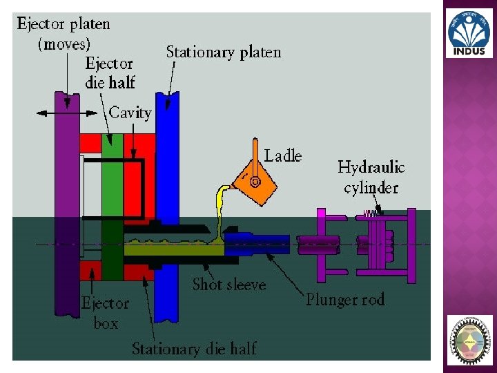
� In cold chamber die casting machine the melting unit is separate and molten metal is transferred to injection mechanism by ladle. The pressure is vary from 21 to 210 MPa and in some cases may reach to 700 MPa. � More pressure is required for semi-molten alloys to compensate for reduced fluidity resulting from low temperature. � This process is used for casting Aluminum, magnesium, copper base alloys. � The machine consists of a pressure chamber of cylindrical shape fitted with piston or ram that is operated by hydraulic pressure. A measured quantity of molten metal is brought in to a ladle and forced in to the closed die sections by applying hydraulic pressure on piston.

� The metal is loaded in the chamber. � The plunger forces the metal into the die cavity. � After the metal solidifies the die is opened. � The casting, together with slag of the excess � Metal, is ejected from the die.

� The rapid and economical production of large quantities of identical parts can be achieved. � Smooth surfaces and close dimensional tolerances may be produced. � Thin and complex shape can be casted accurately and easily. � Less floor area is required then other casting processes. � The products are less defective. � The rapid cooling rate produces high strength and quality in many alloys. � The die retains its life for longer period.

� The cost of equipments and die is high. � Limited range of non-ferrous alloys used for die casting. � The die casting are limited to size. � It requires special skill in maintenance.

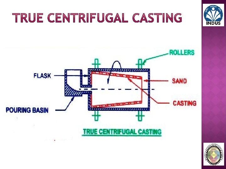
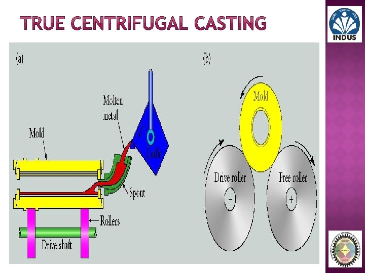
� A casting processes in which molten metal is poured and allowed to solidify while mould revolving. � The centrifugal casting are classified as 1. True centrifugal casting 2. Semi- centrifugal casting 3. Centrifuging

� It is used for casting of symmetrical shape. Cast iron pipe, sleeves, steel gun barrels and other casting of cylindrical form. � In this process the mould is made of metal and lined with refractory material or sand. � The molten metal is poured by ladle into the cavity of rapidly rotating mould. � The centrifugal force directs the fluid metal to the inner surface of the mould with considerable pressure where solidification occurs forming hollow castings. � The out side of the mould is covered by water bath for quick cooling of metal.

� � � It is a quick and economical than other method. It eliminates the use of risers, feed heads, cores. The ferrous and non-ferrous metals can be casted by this process. � The castings produced by this process have dense and fined grained structure with all impurities forced back to the centre where they can be frequently machined out.

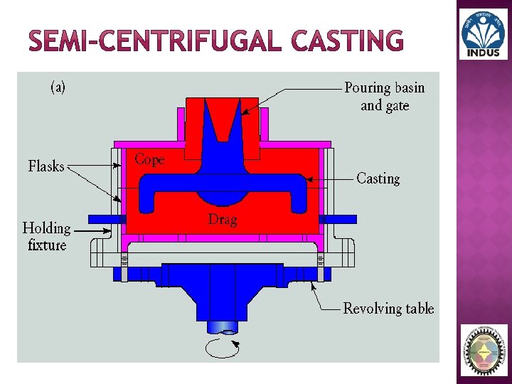
� This process is used for making large size castings which are symmetrical about their own axis such as pulleys. � In this process the mould is rotated about its vertical axis, and the molten metal is poured into a central Sprue from where it enters the hub. From the hub it is forced outward to the rim by centrifugal force. � If a central hole is required in the casting, a dry sand central core may be used in center. � The speed of rotation is less than that of true centrifugal casting. This is due to the large size casting and there is a tendency of the molten metal to flow out of the mould joint. � Due to the lower speed the pouring pressure produced is low and thus the impurities are not effectively separated from the metal.

� The casting of irregular shape can produced and the large number of small size castings can be produced at one time. � In this process a number of small cavities are made symmetrically around a common central Sprue and the metal is fed to them by radial gates. The mould cavities are not rotated about their own axis but they are rotated about the central Sprue which acts as the axis of rotation.

� The rapid and economical production of large quantities of identical parts can be achieved. � Smooth surfaces and close dimensional tolerances may be produced. � Thin and complex shape can be casted accurately and easily. � Less floor area is required then other casting processes. � The products are less defective. � The rapid cooling rate produces high strength and quality in many alloys. � The die retains its life for longer period.

� The cost of equipments and die is high. � Limited range of non-ferrous alloys used for die casting. � The die casting are limited to size. � It requires special skill in maintenance.

� Pouring refers to the process by which the molten metal is delivered into the mold. It involves it's flow through the gating system and into the main cavity. � Factors of Pouring: § Pouring Temperature § Pouring Rate § Turbulence

� Pouring temperature refers to the initial temperature of the molten metal used for the casting as it is poured into the mold. � This temperature will obviously be higher than the solidification temperature of the metal. � The difference between the solidification temperature and the pouring temperature of the metal is called the superheat.

� Volumetric rate in which the liquid metal is introduced into the mold. � Pouring rate needs to be carefully controlled during the metal casting operation, since it has certain effects on the manufacture of the part. � If the pouring rate it too fast then turbulence can result. If it is too slow the metal may begin to solidify before filling the mold.

MELTING FURNACES § Rotary § Pit § Electric § Tilting and § Cupola

� A rotary furnace consists of a refractory lined rotating shell, which is rotated at very low rpm. � The rotary furnace consists of a cylindrical body with two conical ends. � An electric motor drives two of the support rollers which rotate the drum. Hydraulic cylinders enable the furnace to he tilted forward or backward along its longitudinal axis. � Support rollers prevent the furnace from slipping in the longitudinal direction charging is done through the waste gas aperture, after the furnace has been tilted forwards by 30°.
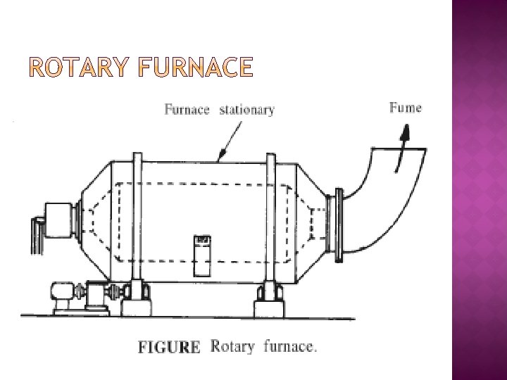

The melting capacity and energy consumption of a rotary furnace are influenced by the following parameters: � Tapping temperature � Temperature of refractory lining � Scrap lumpiness and specific surface � Percentage of steel scrap � Furnace geometry � Degree of filling � Flame temperature � Furnace rpm � Flame shape and length � Fuel � Carburization time.


- Slides: 171