Preliminary Afterlaunch GOCI Characterization Interslot radiance discrepancy issue


 • Slot #2 -7 border")
 • Slot #3 -6 border")


 GOCI 20110412 -07 h, South Japan")
 GOCI 20110412 -07 h, South Japan")


- Slides: 44
Preliminary After-launch GOCI Characterization: Inter-slot radiance discrepancy issue Young-Je Park*, Hee-Jeong Han, Seongick Cho, Joo-Hyung Ryu, Jae-Hyun Ahn and Yu-Whan Ahn Korea Ocean Satellite Center, Korea Ocean Research and Development Institute Presented at IGARSS 2011, Vancouver, Canada
Objectives • To understand the inter-slot radiance discrepancy issue • To seek ideas/suggestions on how to approach this GOCI specific issue
Sensors have specific issues • MODIS stripe noise – detector calibration – difference in mirror side characteristics – Sensitivity to polarization state • MERIS – SMILE effects: wavelength variation – Discontinuity at some camera interface
Outline • Overview of the GOCI optical system and image acquisition sequence • Inter-slot discrepancy: – variability within a slot – variability across different slot boundaries – variability with observation hours (0, 3, 7 hours) – How RT simulations show • Image smoothing technique • Future directions
GOCI sensor
GOCI optical layout Three Mirror Anastigmatic Telescope
GOCI slots imaging sequence 1 2 8 3 4 7 6 5 9 10 11 12 16 15 14 13
Imaging procedure for a GOCI slot
Nominal time intervals for GOCI operation • Interval between bands = ~ 8 seconds • Interval between consecutive L 1 a slots = ~ 103 seconds • Duration for acquiring one GOCI image = ~ 103*16 seconds = 27 minutes • Interval between consecutive GOCI images = one hour • Interval between the adjacent slots in L 1 B scene = up to ~103*7 seconds or 12 minutes => sun angle difference? ?
Requirements for comparing radiances from two slots • Accurate geometric registration • Spatially homogenous conditions for the atmosphere and water are preferred, which is to avoid seeing different air/water mass from two different slots
Inter-slot discrepancy
Variability within a slot • 20110330_0 h image: slot 3 -6 border
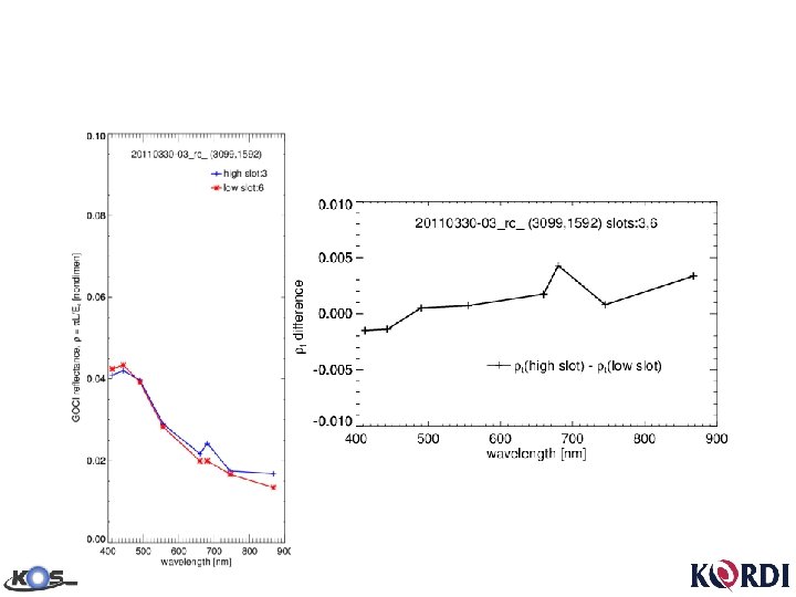
Variability across different slot boundaries • 20110330 -3 h
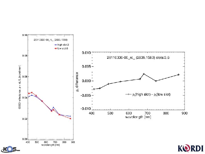
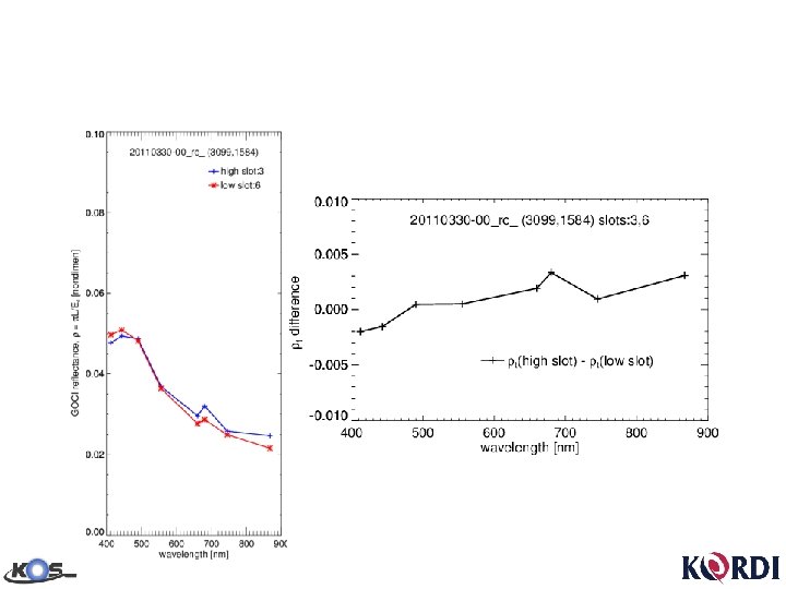
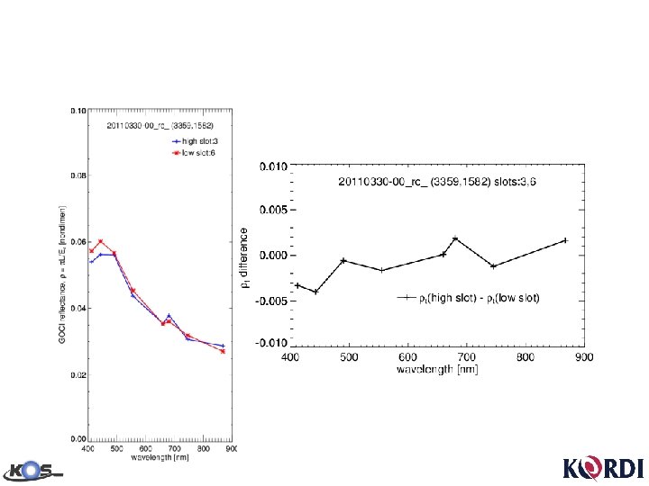
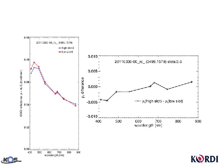
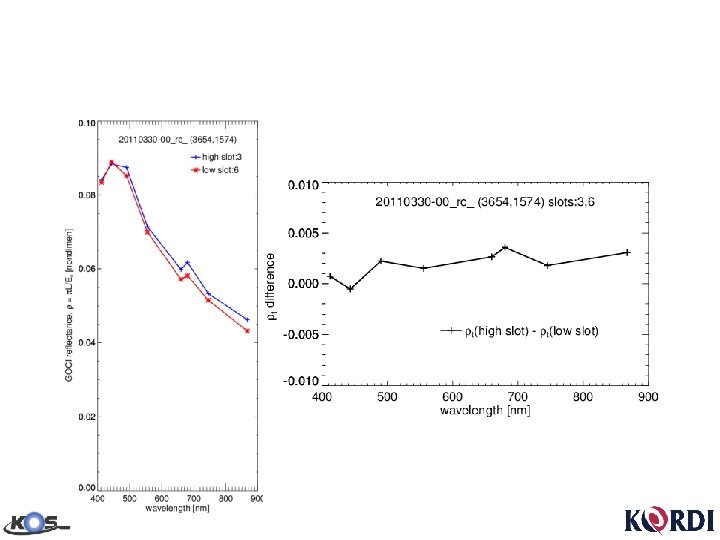
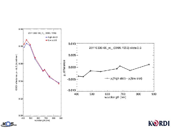
Inter-slot discrepancy: spectral aspect (033003) • Slot #2 -7 border
Inter-slot discrepancy: spectral aspect (033003) • Slot #3 -6 border
• Slot #4 -5 border
• Slot #5 -12 border
• Slot #6 -11 border
• Slot #7 -10 border
• Slot #8 -9 border
• Slot #9 -16 border
• Slot #10 -15 border
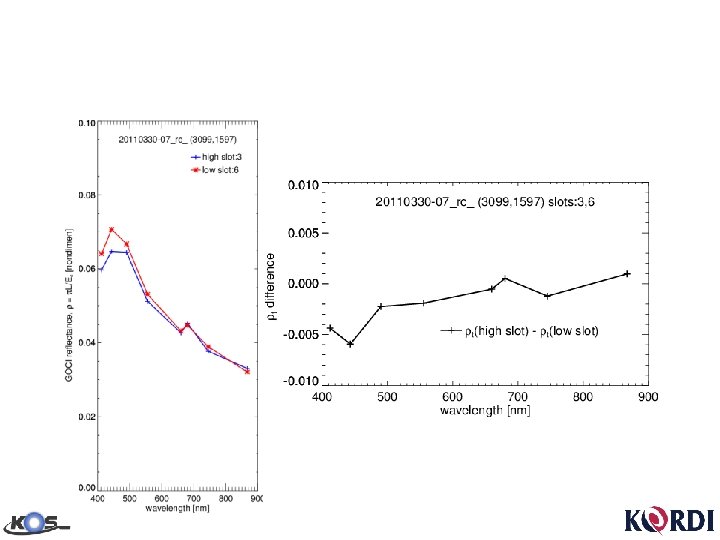
Variability with observation hour
Slot border reflectance change • Within a slot border: moderately variable with consistent difference spectra • For different slot borders: variable magnitude, moderately variable spectra • For different observation hours: larger difference (lower reflectance for the upper slot) in the 7 h image • Bands 7 & 8 reflectance ratio changes significantly, which has a serious effect on atmospheric correction that uses those bands.
How does RT code simulate the discrepancies? 0 h: 9 hr local time • • • 3 h: 12 hr local time 7 h: 17 hr local time uslot=3, lslot=6: 3099, 1584 lat, lon= 41. 0020866 sunz= 54. 8425102 suna= 121. 0095673 senz= 47. 5428658 sena= 185. 6037445 3099, 1585 131. 8832245 54. 0042229 122. 2263718 47. 5378571 185. 6040649 uslot=3, lslot=6: 3099, 1592 lat, lon= 40. 9659882 sunz= 37. 4894829 suna= 180. 6660614 senz= 47. 5027428 sena= 185. 6062317 3099, 1593 131. 8822021 37. 5132179 182. 7969666 47. 4977188 185. 6065369 uslot=3, lslot=6: 3099, 1597 lat, lon= 40. 9434242 sunz= 65. 5979691 suna= 252. 3380127 senz= 47. 4776611 sena= 185. 6077881 3099, 1598 131. 8815613 66. 5323486 253. 3214874 47. 4726372 185. 6080933
Simulation with AOT 550=0. 1 TOA reflectance diference 0. 002 0. 001 0 0 h -0. 001 3 h -0. 002 7 h -0. 003 -0. 004 400 500 600 700 wavelength (nm) 800 900
Simulation with AOT 550=0. 5 TOA reflectance diference 0. 002 0. 001 0 0 h -0. 001 3 h -0. 002 7 h -0. 003 -0. 004 400 500 600 700 wavelength (nm) 800 900
GOCI data TOA reflectance diference 0. 006 0. 004 0. 002 0 0 h -0. 002 3 h -0. 004 7 h -0. 006 -0. 008 400 500 600 700 wavelength (nm) 800 900
An image smoothing technique • Distance-to-border weighted average – Applied to overlapped area – Simple and good for image generation – Smoothing the TOA reflectance data will not be good for downstream data processing including the atmospheric correction. – Smoothing the geophysical parameters would make sense.
Distance-to-border weighted average Slot i d 1 d 4 d 2 wi wj d 3 wi = min(d 1, d 2, d 3, d 4) where is number of pixels to the k-th border Slot j N’=∑(wiⅹNi)/∑wi N’: weighted average Ni: reading from the ith slot
Example 1 (original) GOCI 20110412 -07 h, South Japan
Example 1 (weighted average) GOCI 20110412 -07 h, South Japan
Future work • Clarify questions of – Is it an issue of the GOCI radiometric calibration? – Is it an issue of the band filter properties? – Is it an issue of the ghost image? • Develop a scientifically based model to correct the inter-slot discrepancy. Bands 6, 7, 8 are critical for atmospheric correction.
Thank you! Please contact us if you have any idea on this issue. youngjepark@kordi. re. kr