PREFABRICATED STRUCTURES UNIT III DESIGN PRINCIPLES DISUNITING OF

PREFABRICATED STRUCTURES UNIT III DESIGN PRINCIPLES

DISUNITING OF STRUCTURES • In prefabrication, many elements are prefabricated or assembled or united or joined to form a single structure. • The problem in pre-fabrication is the transportation. • To avoid problem in transportation , the structure is disunited or separated in to smaller member or elements so that the transportation becomes very easy and then they are unite or assembled at site. • The method of separating in to smaller elements is called disuniting of structures in prefabrication.

• Instead of using a larger member as a beam or girder, two or three smaller sections may be used and united together as a single member. • But the load carrying capacity of single member should be equal to the sum of load carrying capacity of 2 (or) 3 smaller members. • There are four methods of disuniting structures.
Systems Consisting of Linear Members disunite at joints: • Disuniting at joints give linear")
a)Systems Consisting of Linear Members disunite at joints: • Disuniting at joints give linear members. • This means a great advantage and facility from the view point of both manufacture and assembly. • Auxiliary scaffoldings are not necessary and the hoisting process is very simple. • The disadvantage of this system is that the joints are at the corners i. e. , at places where moments usually reach their maximum values, so the forming of joints is difficult.

• So the joints must be over dimensioned. • This necessitates additional materials for the precast members too. • The other new trend of replacing moment resistant joints by hinge like ones can also be used.
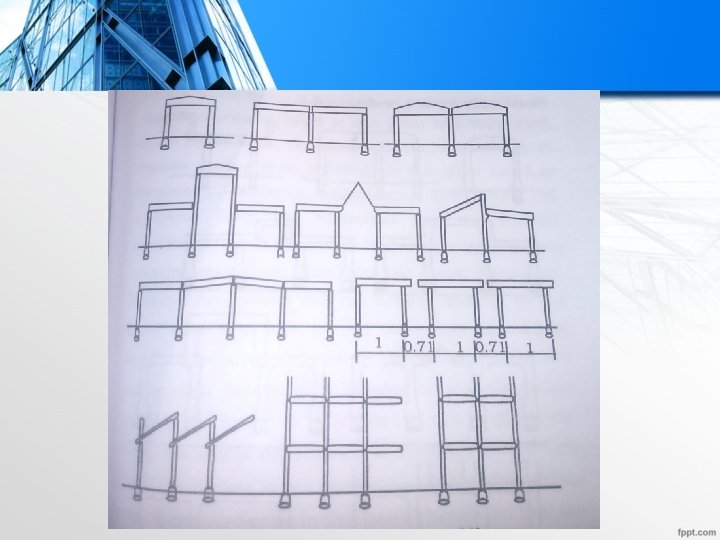
System for the prefabrication of disuniting in to entire rigid frames: • To lessen")
b)System for the prefabrication of disuniting in to entire rigid frames: • To lessen the number of joints and to prefabricate large members in to one leads to the prefabrication of entire frames. • But these kind of prefabricates are only appropriate for site prefabrication. • The drawback of this system is hoisting will be more difficult and requires careful preparation. • The stress distribution of straight members during their hoisting is statically determined.

• The stress distribution arising in frames during their hoisting on the other hand is frequently statically redundant. • It may happen due to tilting of a frame from the horizontal into vertical position when lifted at two points by two separately acting hoisting machines. • If these two points are not hoisted exactly at the same time and with perfect uniformity, the frame itself will be affected by torsions. • Connecting two suspension points by balance or a cable rocker enables the frame to be hoisted at one single point.

• The stress distribution is statically determined. • If the rocker is not suspended at the exact same point torsion can also arise in this case. • Hoisting of asymmetric frames are more difficult. • This shows that hoisting of a frame is far more complicated than hoisting a straight member. • Entire frames are prefabricated on the ground close to their final location. • They can also be produced in a vertical position side by side.

• The advantages of prefabricating entire frames are small number of joints are only needed and the possibility of rapid hoisting work. • This method can be very much handy in construction of large walls consisting of great number of uniform frames.
System consisting of L, T and U shaped or straight members disunited at points")
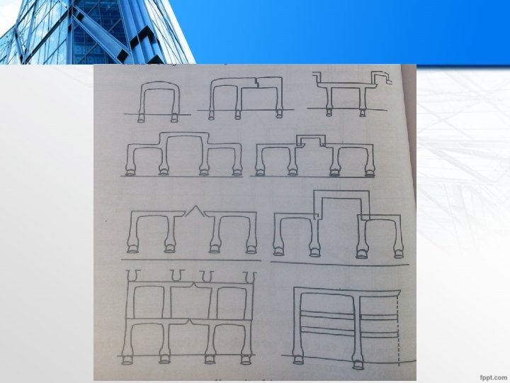
c)System consisting of L, T and U shaped or straight members disunited at points of minimum moments: • Another method for the disuniting of structures is their division into members at points where the moments are smallest. • This method is called “Lambda method” in some countries. • Difficulties met with carrying out a moment-bearing junction at a place where the moment is greater led to this method. • Therefore, the junctions must be re-sited in places the moments are smallest.

• Hinge-like joints can also be formed while joining. • The drawback of this method is hoisting. • The hoisting and temporary bracing of L-shaped asymmetric frame member is particularly complicated. • The joining of members are also not less complicated. • The joints are dimensioned for the bearing of other adjoining member is necessitated.

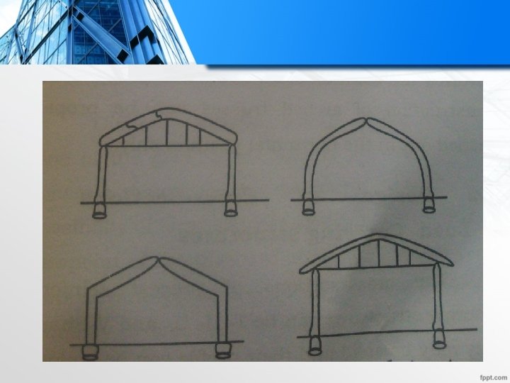
Two-Hinged and Three-hinged Arches: • Arched structures are normally used for bridging spans of")
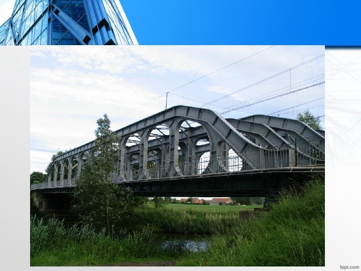
d)Two-Hinged and Three-hinged Arches: • Arched structures are normally used for bridging spans of more than 20 -25 m. • Production and placing is more difficult than that of straight members but as they demand little material, their use for long span structures is economical. • Arches can be two and three hinged, but they can also be fixed at footings. • Arched structures are usually prefabricated and assembled in statically determined three hinged variant.

• The middle hinge is eliminated after placing is finished. • The reinforcing bars protruding from both members are welded together and the joint between the member is filled with in site concrete. • Thus the structure is transformed in to hinged arch, increasing thereby its rigidity as well reducing its motion under wind load.

DESIGN OF CROSS-SECTION BASED ON EFFICIENCY OF MATERIAL: • Prefabricates can be classified as homogeneous and composite materials based on number of materials used in the fabrication. i)Homogenous Prefabricates • Only one material is used for fabrication. • They may classified as -Solid -Hollow -Ribbed
Composite Material • A prefabricate with more than one material is called as composite")
ii)Composite Material • A prefabricate with more than one material is called as composite prefabricate. • Here many materials in different layers unite together to form a single pre-fabricate or a sandwich Cored unit. • Each & every individual layer of these prefabricates may take various forms of construction. • These are classified as a)Solid b) Cored section c)Ribbed section
Solid Cross section: • Solid c/s have more than one material with two layers.")
a)Solid Cross section: • Solid c/s have more than one material with two layers. -Structural layer -Non-structural layer. • Structural layer takes the load on the structure and safely resist the load. • Non-structural layer are protective layers and it does not take any load. • Non-structural layers are insulation or finishing layer which protect the structure from thermal radiation or heat.
Cored Sections: • These are sections which have different layer or cores and made")
b)Cored Sections: • These are sections which have different layer or cores and made up of more than material.
Ribbed Section: • They are prefabricated with ribs in it. • These ribs are")
c)Ribbed Section: • They are prefabricated with ribs in it. • These ribs are structural layer and withstand the load. • Here also the non-structural layer or the outer finishing layer is used to protect the structure from heat effect and do not carry any load.

• Another type of composite prefabricate is skeletal prefabricate. • One material forms a frame work and filled with another material which is lighter.

• The cross section of precast reinforced concrete structure can be T, I, U and V-Shaped. • They may be solid and their profile can be hollow or divided (fretted, latticed) and virendeel columns. a)Beams of Rectangular T, I, U, V shaped and hollow cross sections: • Rectangular section is the most simple c/s of pre-cast structures. • These sections are used for lighter members or sections to be produced in small number. • The advantage is simple prefabrication.

• The disadvantage is rectangular sections are not economical. • Hence the sections such as I, Tee, U and V shaped frequently used in prefabrication. • The advantage of these sections are i)30 -50% savings in concrete ii)5 -10% savings in steel iii)Saving cost in hoisting (lifting) work. iv)Less concrete makes a proportionate savings in weight. v)These c/s have internal space effect than the rectangular section.

• The most important advantage of precast concrete structures over monolithic or cast in situ structures is the method and possibility of forming various cross sections as per requirement. • From theory of strength of materials, the sections I, T, U , V and hollow cross sections have more advantage than the rectangular section. • The economy of c/s these sections are very high than the rectangular section. • The economy of c/s is measured by a factor called form factor and it is denoted by ‘ψ’.

• The value of ‘ψ’is ψ = F/F’ Where F = Area of the investigated cross section F’ = Area of a rectangular c/s with the depth ‘h’, width ‘b’ and modulus of resistance ‘k’. For rectangular c/s F’ =bh ……. . . (1) k’ = bh 2/6 = k. . . (2) h = (6 k/b)1/2. . . (3)
1/2 F’ = (6 kb)1/2 ψ = F/F’=F/((6 kb)1/2 ) For")
F’ = b(6 k/b)1/2 F’ = (6 kb)1/2 ψ = F/F’=F/((6 kb)1/2 ) For rectangular cross section, ψ = 1 For other section I, U, T, V shape etc For these c/s, ψ<1 If the value of ψ is smaller, the c/s is more economical. Consider two precast reinforced concrete beams of ‘I’ section and rectangular section of equal load carrying capacity. Consider the values, F=2260 cm 2 , b=48 cm, k=48500 cm 3.

• The depth of equivalent rectangular c/s is h=77 cm. • The form factor of ‘I’ section is ψ = F/F’ =F/((6 kb)1/2 ) = 2260/(6*48500*48)1/2 = 0. 605 • The value of ‘ψ = 0. 605’ means that in case of beams made up of timber, steel or another homogeneous material having same tensile & compressive strength, the application of ‘I’ section instead of rectangular section will save in material of 39. 5%.

• This concept is called as the design of a cross section based on the efficiency of material used in prefabrication. b)Fretted, Latticed and Vierendeel structures • Generally, there is no difference in construction between a solid beam and a fretted section. • The different openings are provided in the fretted beam only to obtain savings in material and to reduce the dead load. • This girder or beam has openings to reduce the dead load and savings in material cost.

• The fretted sections, latticed trusses and vierendeel structures are mainly used in prefabrication because the dead load is very much reduced and a very high material savings is achieved. • These are the design of different c/s based on the efficiency of materials used in prefabricated structures.

JOINT FLEXIBILITY: A joint that holds two parts together so that one can swing relative to other is called joint flexibility. PROBLEMS INVOLVED IN DESIGN DUE TO JOINT FLEXIBILITY: • There are difficulties and problems if the joints of various elements are not proper. • If the joints are not strong then the failure will occur in the structure. • So it is important to solve the problems in design and construction of structures by assembling many precast member.
Any joint should be easy b)Smaller")
• The following points should be considered a)Any joint should be easy b)Smaller inaccuracies will not influence any problem c)Deviations in joint is also leading to problem in design d)Dimensional tolerances (allowances) should not cause many changes in the stresses designed and stressdistribution in the structure.

Important Requirements of a Joint: • Construction of joint should be easy. • Joint should require only little material. • Joint should not consume more labour. • Cost should be minimum. • Greater control in forming and construction of joint is necessary. • Inspection of joints is always important. • Design & construction of joint should match or harmonize with the materials to be used.

• Properties of steel and timber are different from concrete and reinforced concrete. So, the joints similar to those used in timber and steel construction are generally not suitable.
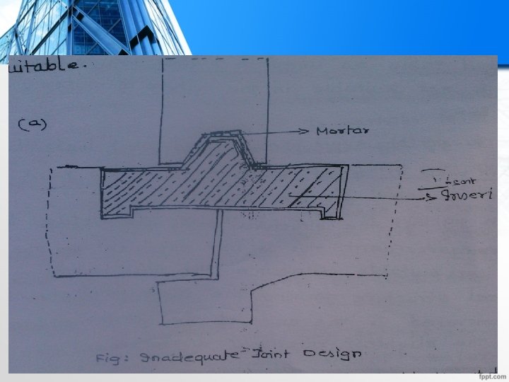

• A butt joint was made with splayed table as used in timber construction. • This kind of joint is not suitable for nature of material like R. C. C

• A pin joint is used which looks like a joint used in steel construction. • So this joint is not suitable for the design.


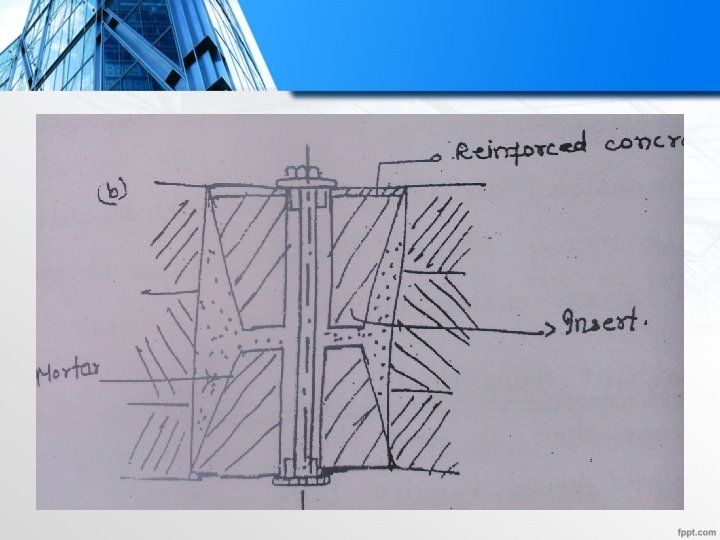
• The structural parts are welded to the reinforcement. • This is not sufficient for the joint. • The two halves of a steel structure forming the main joint should be concreted to the ends of the joint member.

• The threaded sleave coupling of steel bar is also a problem in design of joints. • An important advantage of steel is that its tensile and compressive shear strength differ only to a small extent. • So the joints are relatively simple and easy in steel construction. • Shrinkage during drying and creep in timber is of high degree and affects the method of joints. • Concrete is also subjected to shrinkage but the reinforcement reduces it to certain level.
Plastic concrete used")
• Two important points to be considered in design are a)Plastic concrete used for further concreting of joints and the fluid cement mortar casting are pressed in to the loose gaps. b)After setting, the shrinkage of in-situ concrete and mortar continues with respect to two phases of shrinkage, the codes on RCC permit only reduced stresses for a subsequent in-situ concrete. These are determined as a function of width of the joint or gap to be concreted.

• The joint should be designed and executed by allowing proper dimensional tolerances. • Due to unfavourable force effect or due to a blow, the relative displacement of the joint members should be impossible if the dimensional tolerances are ensured. • The length of the section determined for the transmission of forces should be as short as possible and exclude any excess permissible stress.

• The joints may be - rigid - hinge - shod • Rigid joints are adequate in bearing of tensile, compressive & shear forces and for resisting bending moments. • These joints make relative displacement and relative rotation impossible. • Rigid joints are generally used for junction of column to footings and for joining individual members.

• But rigid joints require considerable man power. • Hinged joints are those which can transmit forces passing through the hinge itself and allow a certain motion & rotation. • Hinged joints are executed simply and requires less time than the rigid joints. • Shod joints are rarely used. • They are used in Industrial construction. • The shod joints are used for long span only.

• Depending on the in-situ concrete, there are two types of joints - Dry joint - Wet joint.

ALLOWANCE FOR JOINT DEFORMATION

- Slides: 53