
Precast Concrete Pipe Design Portland OR Josh Beakley

Precast Concrete Pipe Design Portland, OR Josh Beakley Director of Technical Services www. concrete-pipe. org
2 Outline • Soil-Structure Interaction • Standard Concrete Pipe Design • Special Design of RCP www. concrete-pipe. org
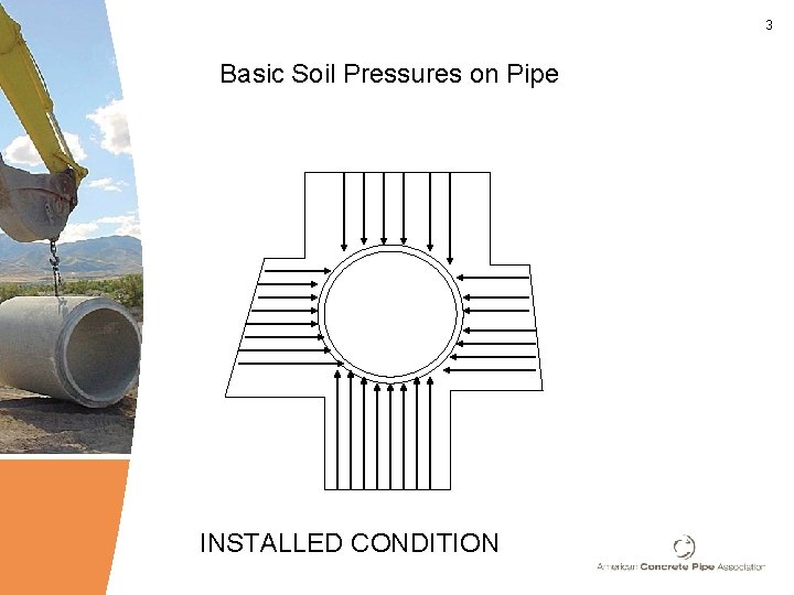
3 Basic Soil Pressures on Pipe INSTALLED CONDITION
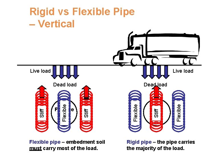
Rigid vs Flexible Pipe – Vertical Live load Flexible pipe – embedment soil must carry most of the load. Flexible Rigid Pipe Stiff Flexible Pipe Dead load Stiff Flexible Stiff Dead load Rigid pipe – the pipe carries the majority of the load.
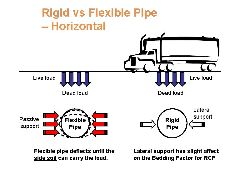
Rigid vs Flexible Pipe – Horizontal Live load Dead load Passive support Flexible Pipe Flexible pipe deflects until the side soil can carry the load. Dead load Rigid Pipe Lateral support has slight affect on the Bedding Factor for RCP

6 Flexible Pipe • Flexible pipe - Can deflect 2% or more without structural damage (cracking).
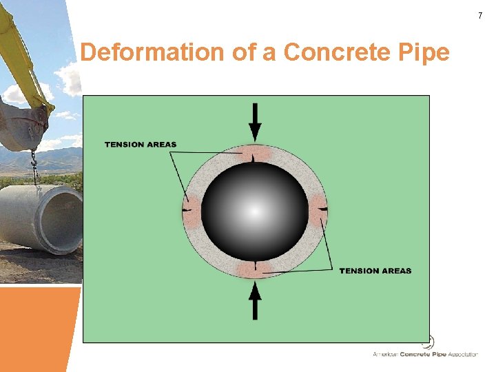
7 Deformation of a Concrete Pipe
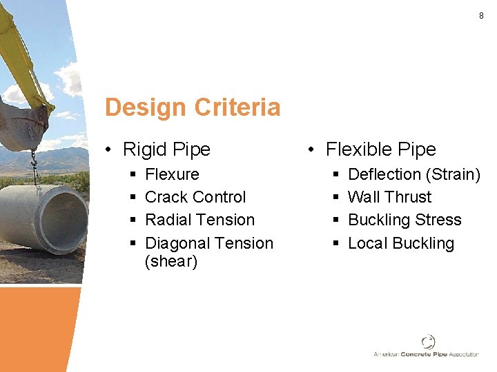
8 Design Criteria • Rigid Pipe § § Flexure Crack Control Radial Tension Diagonal Tension (shear) • Flexible Pipe § § Deflection (Strain) Wall Thrust Buckling Stress Local Buckling
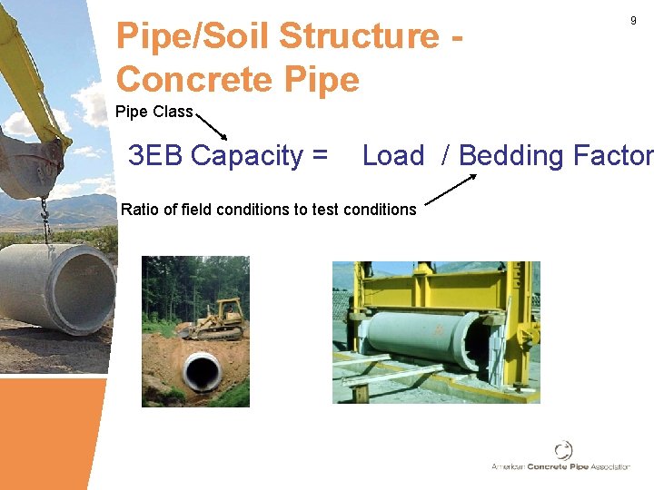
Pipe/Soil Structure Concrete Pipe 9 Pipe Class 3 EB Capacity = Load / Bedding Factor Ratio of field conditions to test conditions

10
11
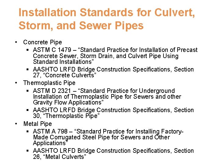
Installation Standards for Culvert, Storm, and Sewer Pipes • Concrete Pipe § ASTM C 1479 – “Standard Practice for Installation of Precast Concrete Sewer, Storm Drain, and Culvert Pipe Using Standard Installations” § AASHTO LRFD Bridge Construction Specifications, Section 27, “Concrete Culverts” • Thermoplastic Pipe § ASTM D 2321 – “Standard Practice for Underground Installation of Thermoplastic Pipe for Sewers and other Gravity Flow Applications” § AASHTO LRFD Bridge Construction Specifications, Section 30, “Thermoplastic Pipe” • Metal Pipe § ASTM A 798 – “Standard Practice for Installing Factory. Made Corrugated Steel Pipe for Sewers and Other Applications” § AASHTO LRFD Bridge Construction Specifications, Section 26, “Metal Culverts”
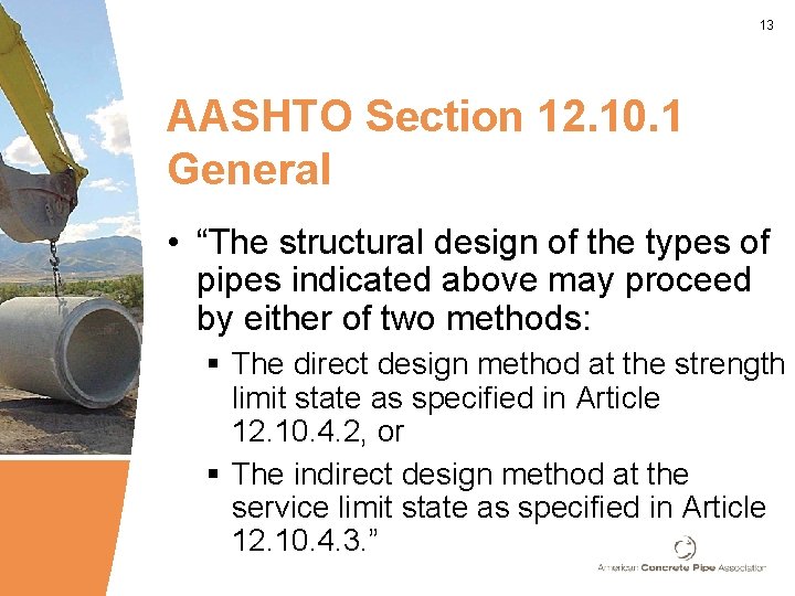
13 AASHTO Section 12. 10. 1 General • “The structural design of the types of pipes indicated above may proceed by either of two methods: § The direct design method at the strength limit state as specified in Article 12. 10. 4. 2, or § The indirect design method at the service limit state as specified in Article 12. 10. 4. 3. ”
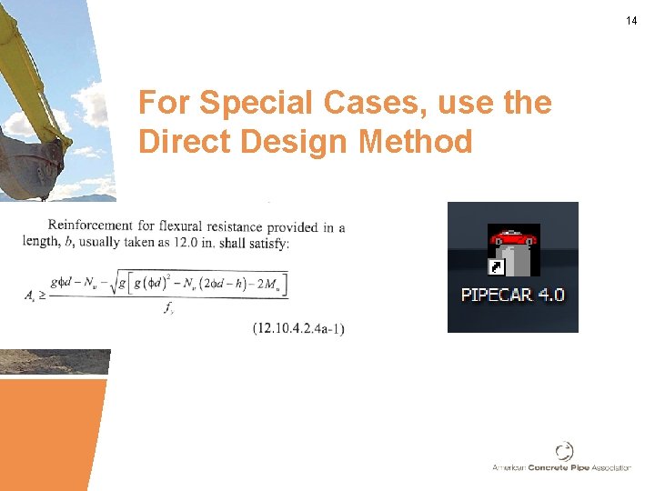
14 For Special Cases, use the Direct Design Method
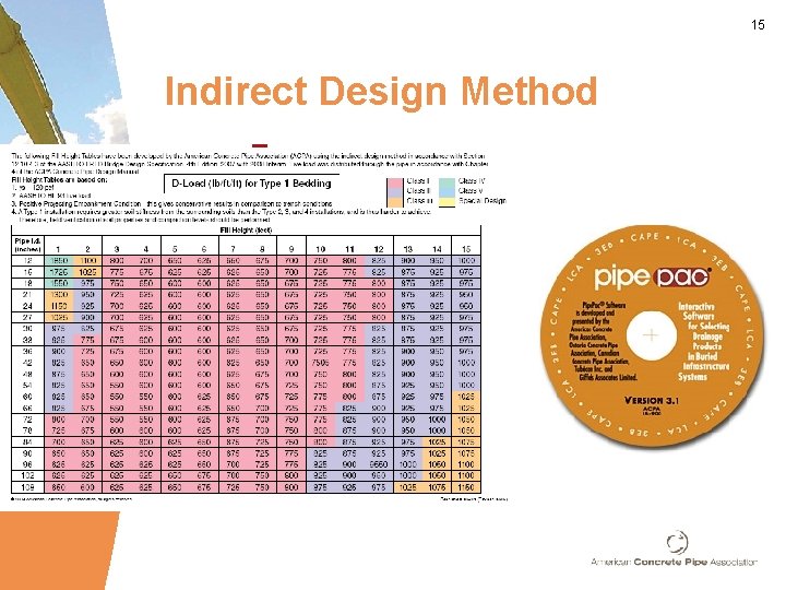
15 Indirect Design Method
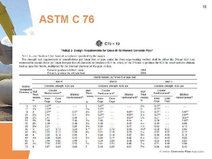
16 ASTM C 76

17 ASCE Standard 15 -93 American Society of Civil Engineers Standard Practice for Direct Design of Buried Precast Concrete Pipe Using Standard Installations (SIDD)
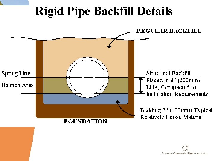
18 Design and Installation • Standard Installations § Developed by ASCE (15 -93) § Adopted by AASHTO (Sections 17 & 27) § LRFD Section 12 and Section 27 of Construction Standard
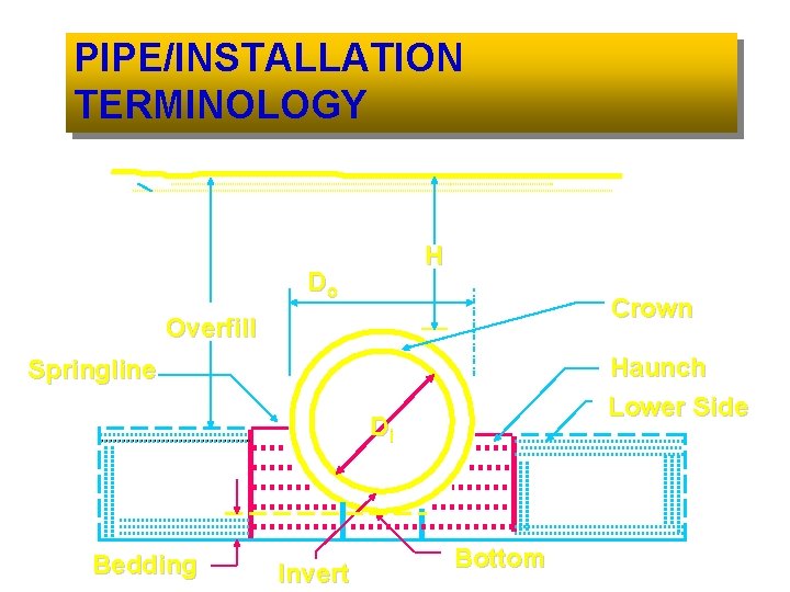
PIPE/INSTALLATION TERMINOLOGY H Do Crown Overfill Haunch Lower Side Springline Di Bedding Invert Bottom
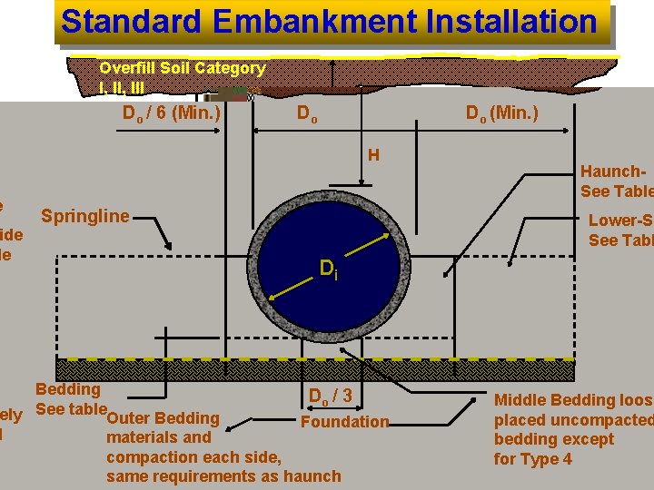
Standard Embankment Installation Overfill Soil Category I, III Do / 6 (Min. ) Do Do (Min. ) H Springline Haunch. See Table Lower-Side See Table Di Bedding Do / 3 See table Outer Bedding Foundation materials and compaction each side, same requirements as haunch Middle Bedding loosely placed uncompacted bedding except for Type 4
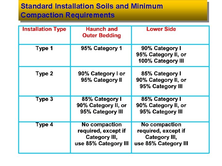
Standard Installation Soils and Minimum Compaction Requirements
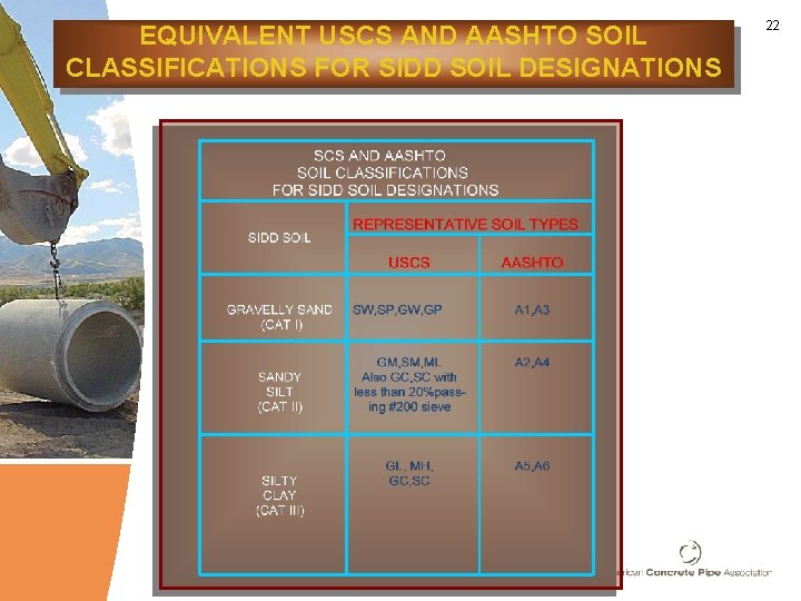
EQUIVALENT USCS AND AASHTO SOIL CLASSIFICATIONS FOR SIDD SOIL DESIGNATIONS 22
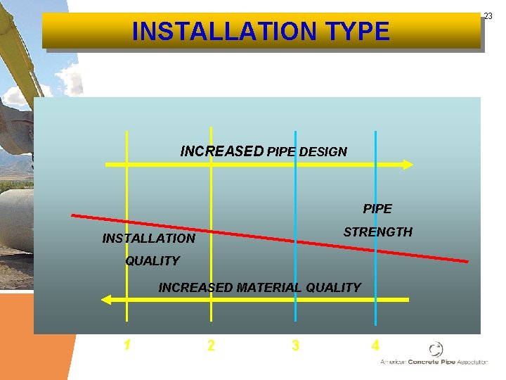
INSTALLATION TYPE INCREASED PIPE DESIGN PIPE STRENGTH INSTALLATION QUALITY INCREASED MATERIAL QUALITY 1 2 3 4 23
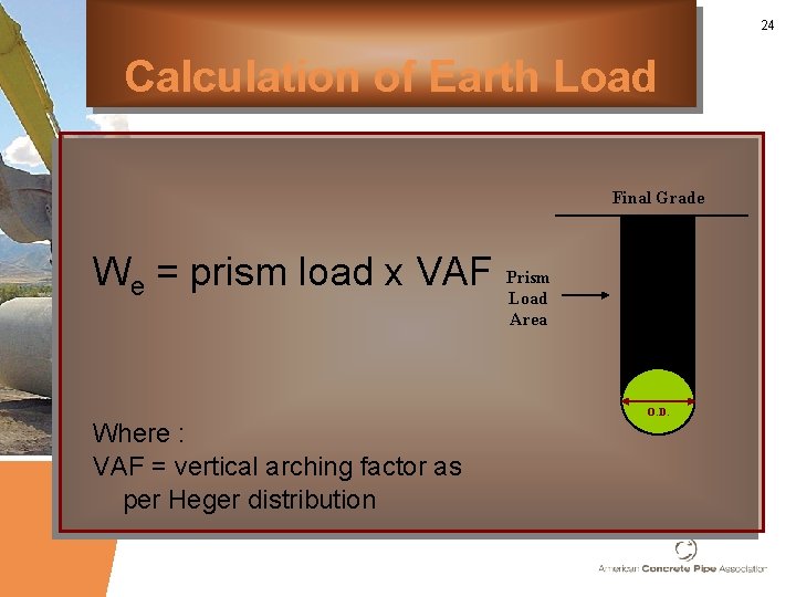
24 Calculation of Earth Load Final Grade We = prism load x VAF Where : VAF = vertical arching factor as per Heger distribution Prism Load Area O. D.
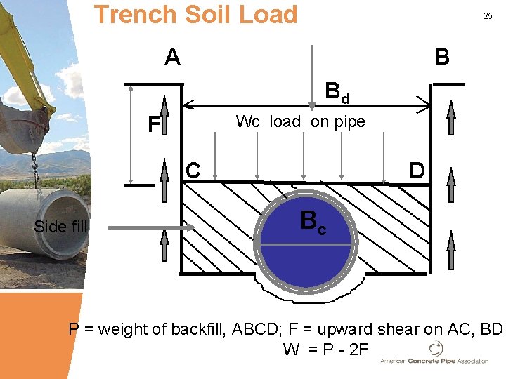
Trench Soil Load 25 A B Bd F Wc load on pipe C Side fill D Bc P = weight of backfill, ABCD; F = upward shear on AC, BD W = P - 2 F
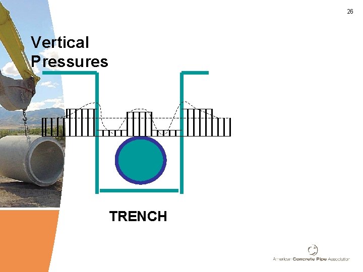
26 Vertical Pressures TRENCH
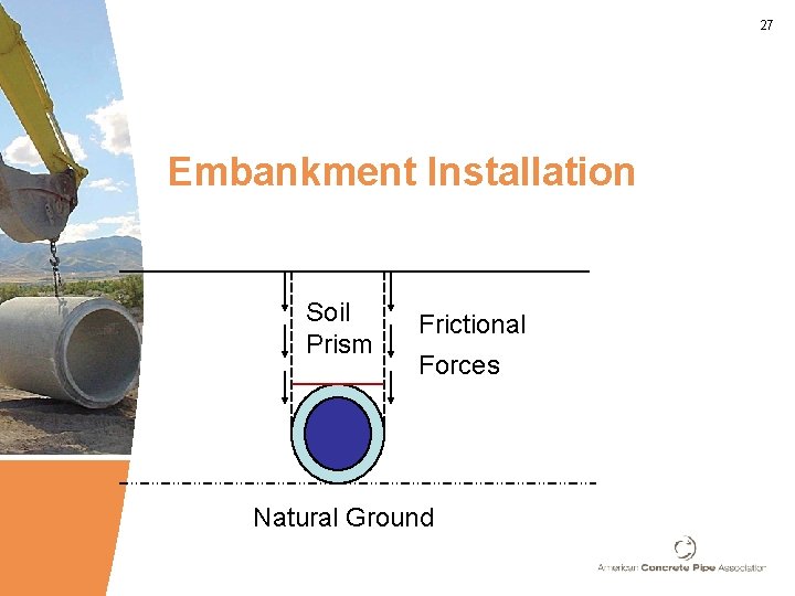
27 Embankment Installation Soil Prism Frictional Forces Natural Ground

28 Vertical Pressure s

29 www. concrete-pipe. org
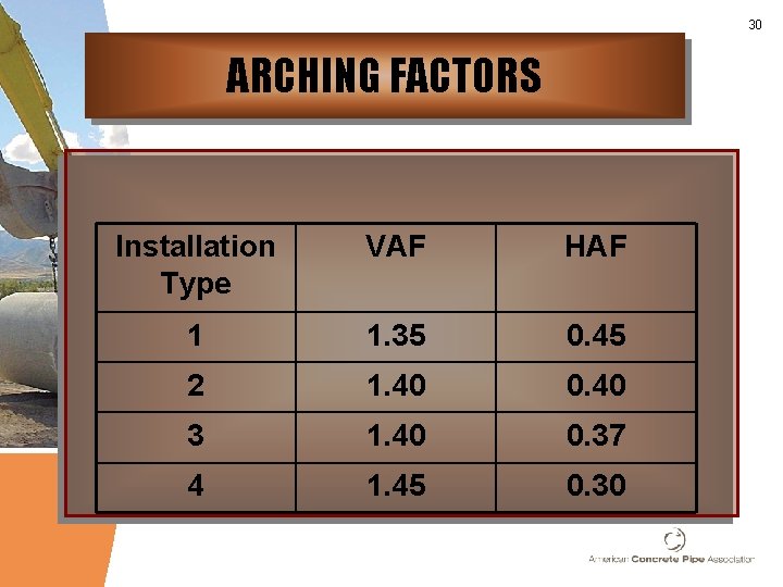
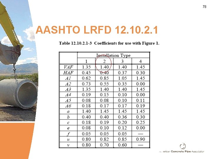
30 ARCHING FACTORS Installation Type VAF HAF 1 1. 35 0. 45 2 1. 40 0. 40 3 1. 40 0. 37 4 1. 45 0. 30
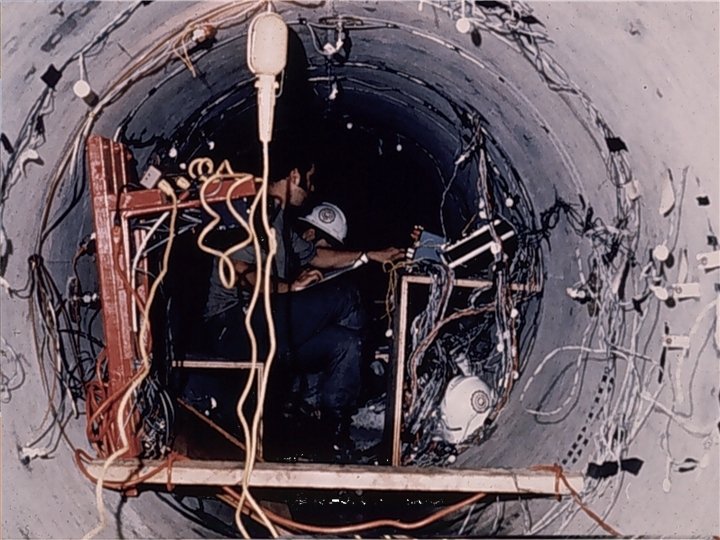
31 Embankment Installation Soil Prism Frictional Forces Natural Ground
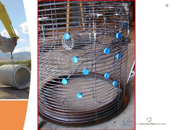
32
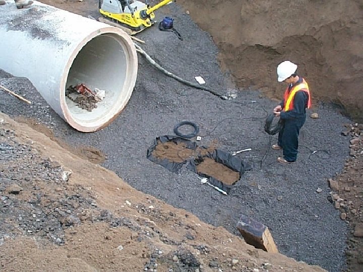
33
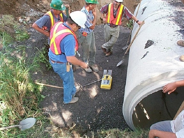
34

35 DC Power Supply Data Acquisition Sys
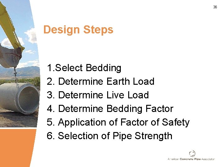
36 Design Steps 1. Select Bedding 2. Determine Earth Load 3. Determine Live Load 4. Determine Bedding Factor 5. Application of Factor of Safety 6. Selection of Pipe Strength
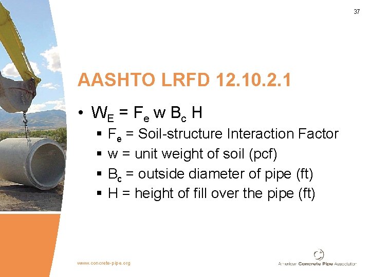
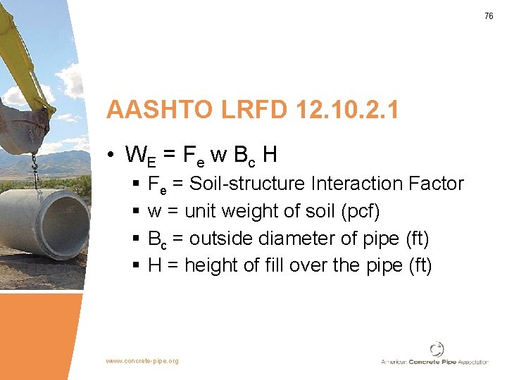
37 AASHTO LRFD 12. 10. 2. 1 • WE = F e w B c H § § Fe = Soil-structure Interaction Factor w = unit weight of soil (pcf) Bc = outside diameter of pipe (ft) H = height of fill over the pipe (ft) www. concrete-pipe. org
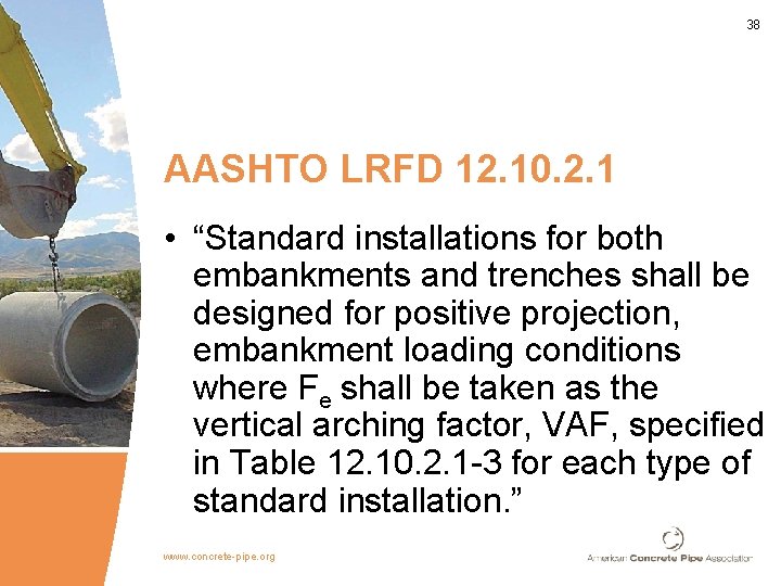
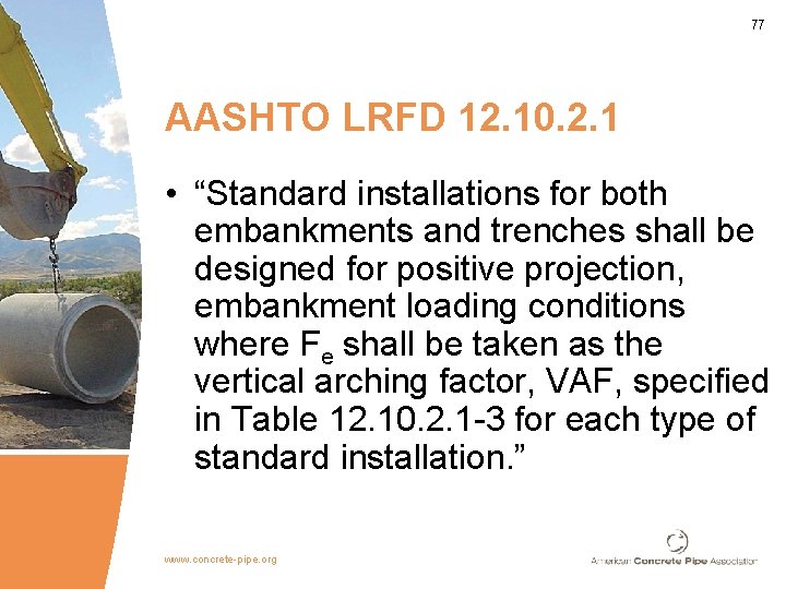
38 AASHTO LRFD 12. 10. 2. 1 • “Standard installations for both embankments and trenches shall be designed for positive projection, embankment loading conditions where Fe shall be taken as the vertical arching factor, VAF, specified in Table 12. 10. 2. 1 -3 for each type of standard installation. ” www. concrete-pipe. org
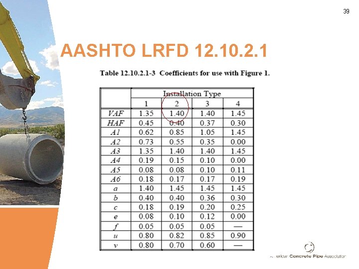
39 AASHTO LRFD 12. 10. 2. 1
40 AASHTO LRFD 12. 10. 2. 2 – Pipe Fluid Weight • “The unfactored weight of fluid, WF, in the pipe shall be considered in design based on a fluid weight of 62. 4 lb. /ft 3, unless otherwise specified. ” www. concrete-pipe. org
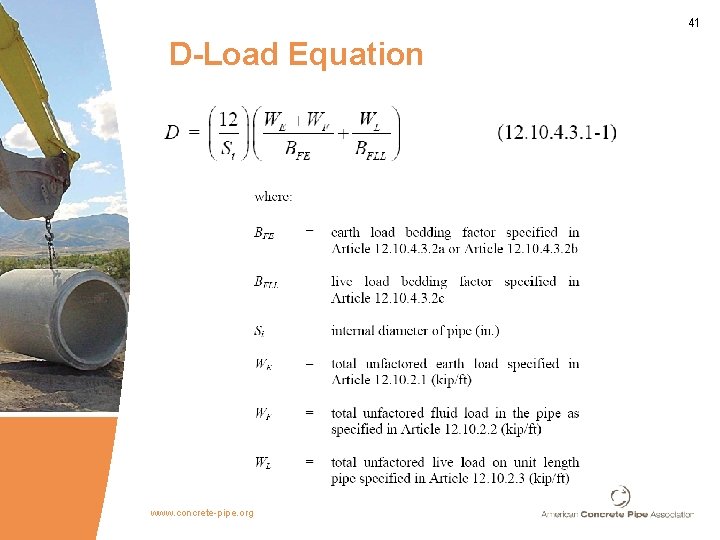
41 D-Load Equation www. concrete-pipe. org
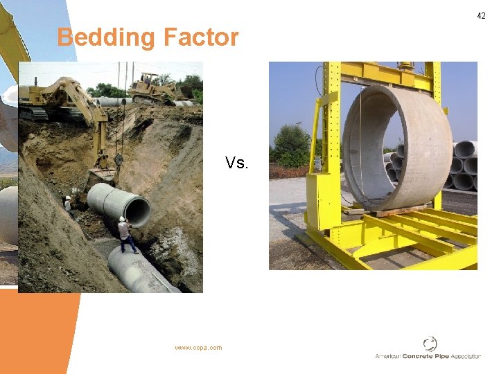
42 Bedding Factor Vs. www. ccpa. com
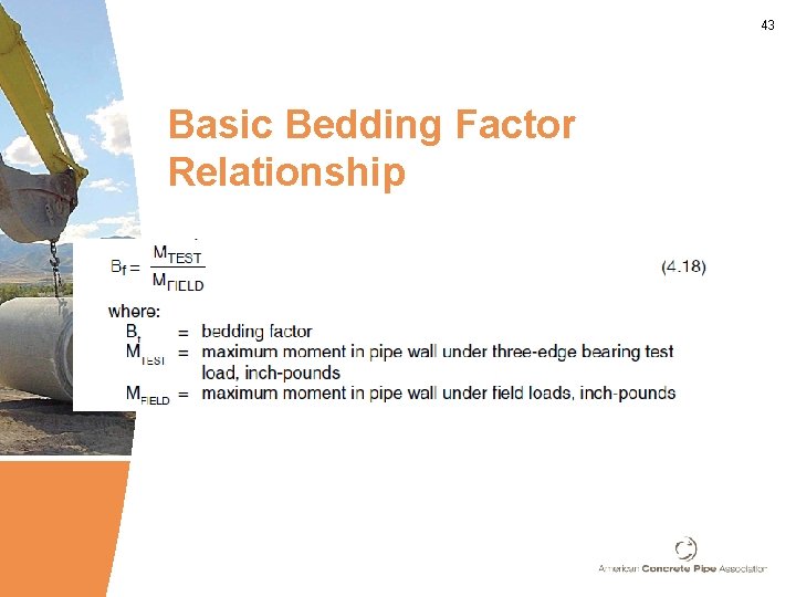
43 Basic Bedding Factor Relationship
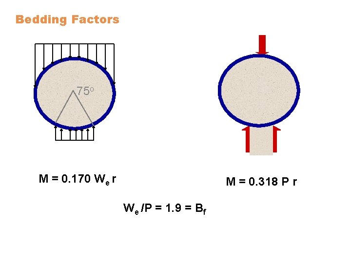
Bedding Factors 75 o M = 0. 170 We r M = 0. 318 P r We /P = 1. 9 = Bf
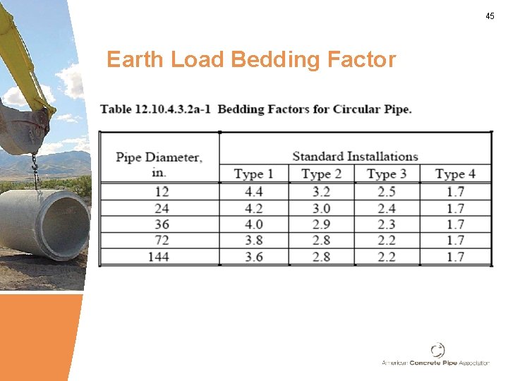
45 Earth Load Bedding Factor
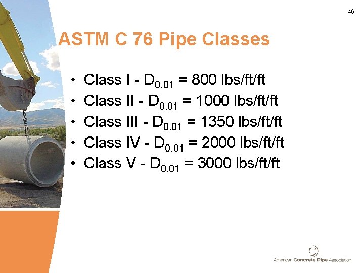
46 ASTM C 76 Pipe Classes • • • Class I - D 0. 01 = 800 lbs/ft/ft Class II - D 0. 01 = 1000 lbs/ft/ft Class III - D 0. 01 = 1350 lbs/ft/ft Class IV - D 0. 01 = 2000 lbs/ft/ft Class V - D 0. 01 = 3000 lbs/ft/ft

AASHTO LIVE LOAD DESIGN
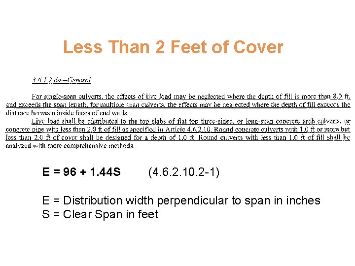
Less Than 2 Feet of Cover E = 96 + 1. 44 S (4. 6. 2. 10. 2 -1) E = Distribution width perpendicular to span in inches S = Clear Span in feet
49 Less Than 2 Feet of Cover Espan = Distribution width parallel to span in inches Espan = LT + LLDF(H) LT = length of contact area parallel to span (in) LLDF = live load distribution factor H = depth of fill
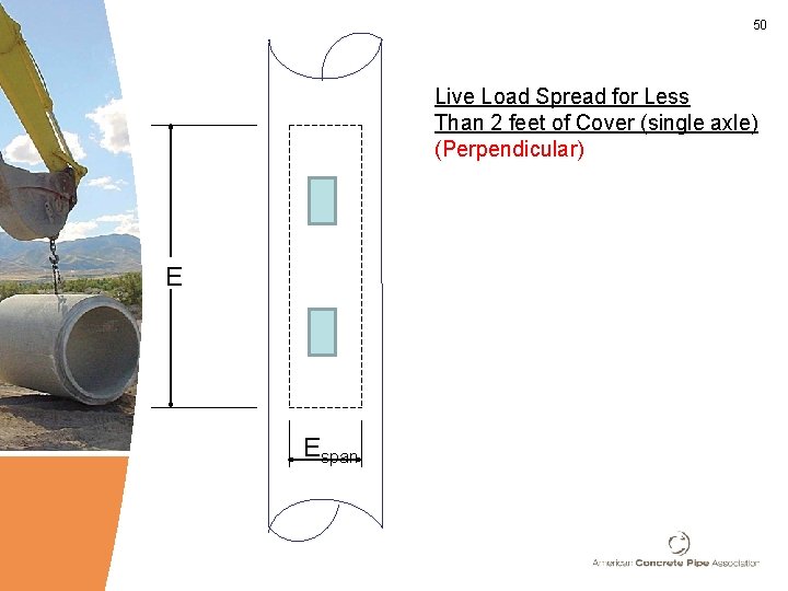
50 Live Load Spread for Less Than 2 feet of Cover (single axle) (Perpendicular) E Espan
51 For Trucks Traveling Parallel to the Axis of the Pipe E = 96 + 1. 44 S (4. 6. 2. 10. 2 -1) E = Distribution width perpendicular to span in inches S = Clear Span in feet Note: Equation 4. 6. 2. 10. 2 -1 is for an axle load. with pipe, having much smaller spans than boxes a distribution for wheel loads is more appropriate. Ewheel = 48 + 0. 72 S
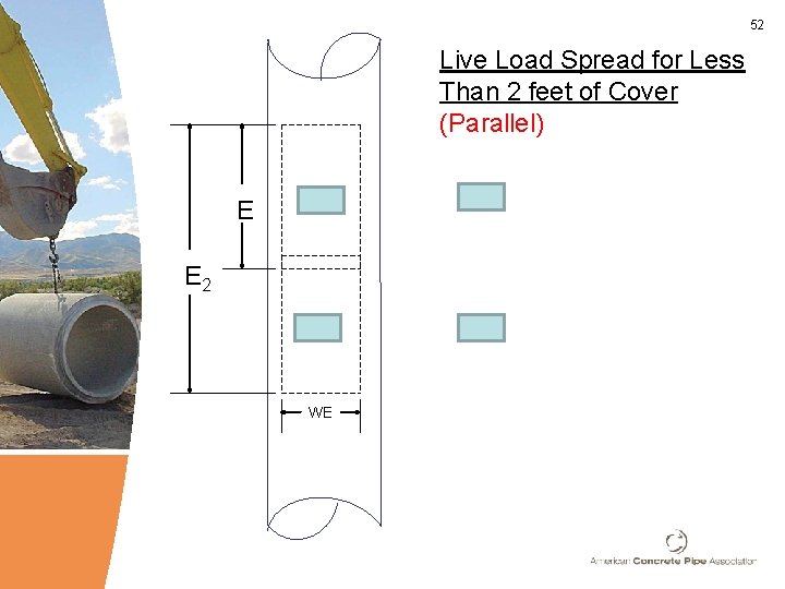
52 Live Load Spread for Less Than 2 feet of Cover (Parallel) E E 2 WE
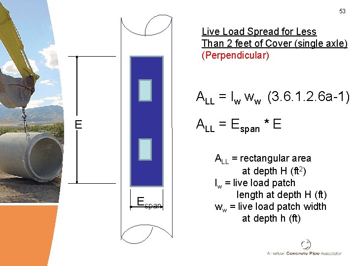
53 Live Load Spread for Less Than 2 feet of Cover (single axle) (Perpendicular) ALL = lw ww (3. 6. 1. 2. 6 a-1) ALL = Espan * E E Espan ALL = rectangular area at depth H (ft 2) lw = live load patch length at depth H (ft) ww = live load patch width at depth h (ft)
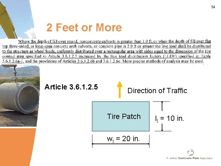
54 2 Feet or More Article 3. 6. 1. 2. 5 Direction of Traffic Tire Patch wt = 20 in. lt = 10 in.
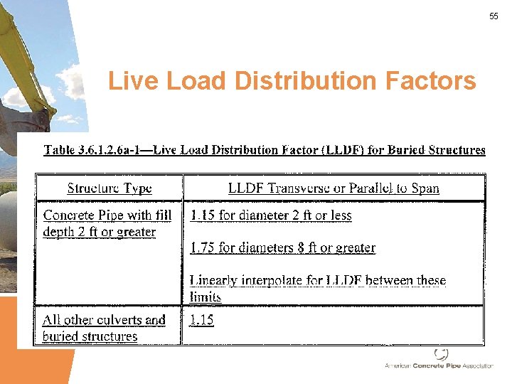
55 Live Load Distribution Factors
56
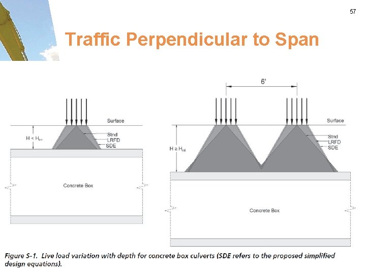
57 Traffic Perpendicular to Span
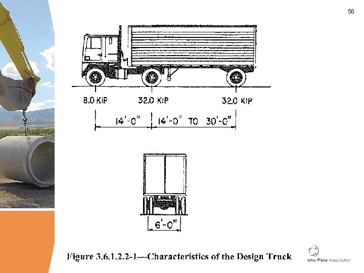
58 Wheel and Axle Spacing • sw = wheel spacing, 6. 0 ft. • sa = axle spacing (ft)
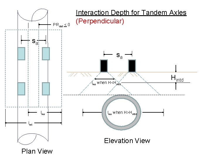
PRdist < 0 Interaction Depth for Tandem Axles (Perpendicular) sa sa lws when H<Hintd lws lwtwhen. H>Hintd lwt Elevation View Plan View Hintd

Interaction Depth for Wheels (Perpendicular) Wws for a single wheel sw Wws for two wheels Plan View sw Hintw Wws if H< Hintw Wws if H> Hintw Elevation View
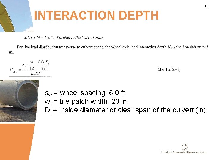
61 INTERACTION DEPTH sw = wheel spacing, 6. 0 ft wt = tire patch width, 20 in. Di = inside diameter or clear span of the culvert (in)
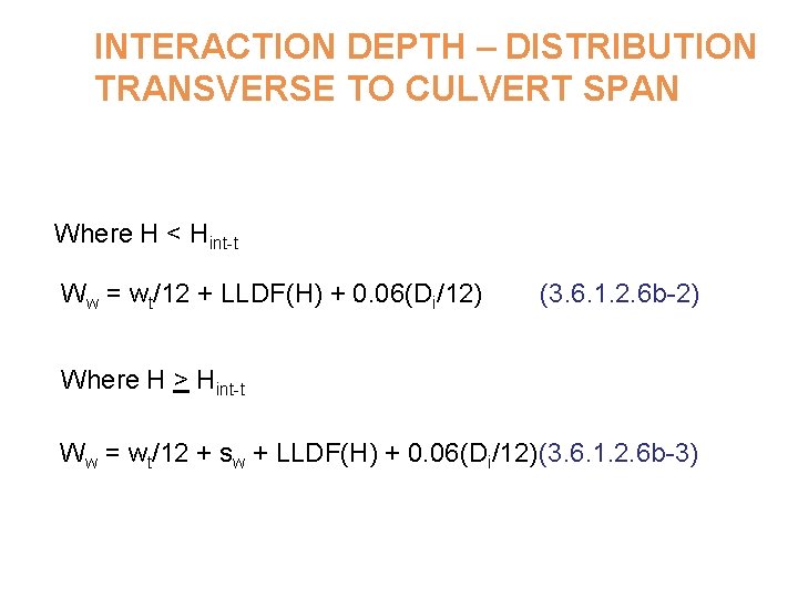
INTERACTION DEPTH – DISTRIBUTION TRANSVERSE TO CULVERT SPAN Where H < Hint-t Ww = wt/12 + LLDF(H) + 0. 06(Di/12) (3. 6. 1. 2. 6 b-2) Where H > Hint-t Ww = wt/12 + sw + LLDF(H) + 0. 06(Di/12)(3. 6. 1. 2. 6 b-3)

63 Interaction Depth Parallel “For live load distribution parallel to culvert span, the wheel/axle load Interaction depth Hint-p shall be determined as: ” Hint-p = lt sa 12 LLDF (3. 6. 1. 2. 6 b-4) sa = axle spacing (ft) lt = tire patch length, 10 (in) LLDF = live load distribution factor
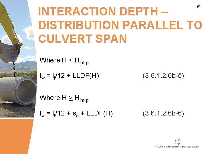
64 INTERACTION DEPTH – DISTRIBUTION PARALLEL TO CULVERT SPAN Where H < Hint-p lw = lt/12 + LLDF(H) (3. 6. 1. 2. 6 b-5) Where H > Hint-p lw = lt/12 + sa + LLDF(H) (3. 6. 1. 2. 6 b-6)
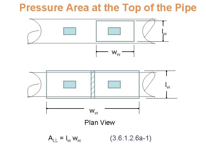
Pressure Area at the Top of the Pipe lw ww Plan View ALL = lw ww (3. 6. 1. 2. 6 a-1)
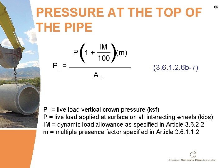
PRESSURE AT THE TOP OF THE PIPE PL = ( ) IM P 1+ (m) 100 ALL (3. 6. 1. 2. 6 b-7) PL = live load vertical crown pressure (ksf) P = live load applied at surface on all interacting wheels (kips) IM = dynamic load allowance as specified in Article 3. 6. 2. 2 m = multiple presence factor specified in Article 3. 6. 1. 1. 2 66

67 Dynamic Load Allowance • LRFD – Dynamic Load Allowance (3. 6. 2. 2) § DLA = 33(1. 0 - 0. 125 DE) • DE = Depth of cover (ft)
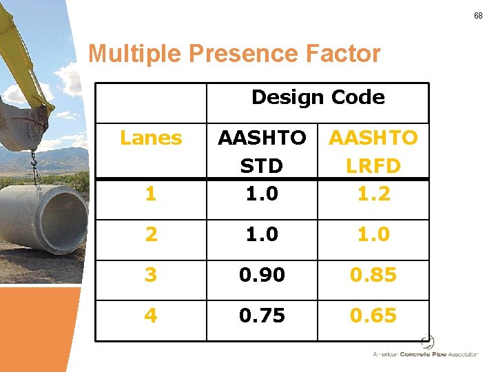
68 Multiple Presence Factor Design Code Lanes 1 AASHTO STD 1. 0 AASHTO LRFD 1. 2 2 1. 0 3 0. 90 0. 85 4 0. 75 0. 65
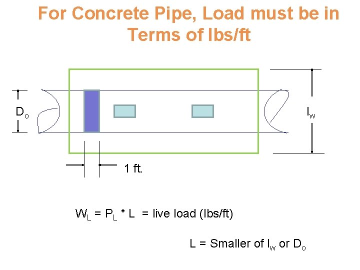
For Concrete Pipe, Load must be in Terms of lbs/ft Do lw 1 ft. WL = PL * L = live load (lbs/ft) L = Smaller of lw or Do
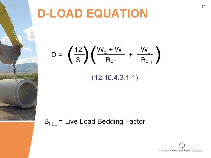
70 D-LOAD EQUATION D= ( )( 12 Si WE + W F + BFE WL BFLL (12. 10. 4. 3. 1 -1) BFLL = Live Load Bedding Factor )
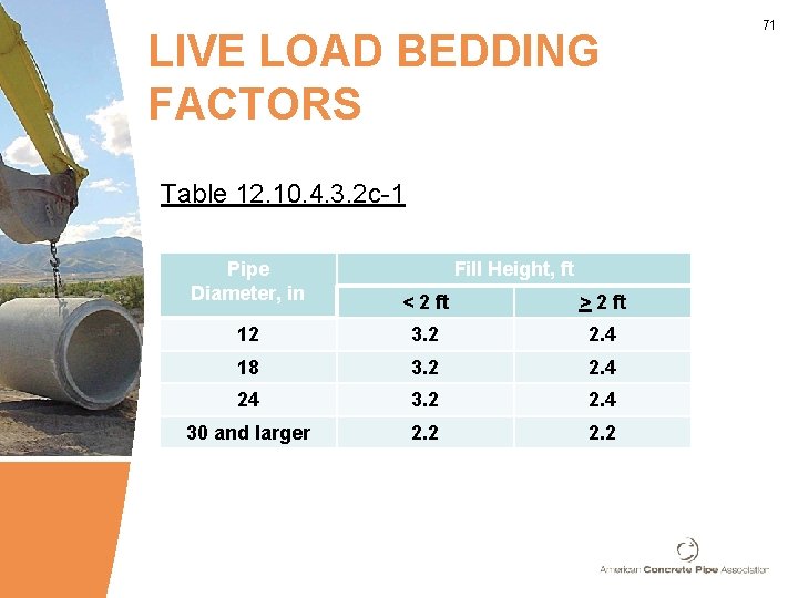
LIVE LOAD BEDDING FACTORS Table 12. 10. 4. 3. 2 c-1 Pipe Diameter, in Fill Height, ft < 2 ft > 2 ft 12 3. 2 2. 4 18 3. 2 2. 4 24 3. 2 2. 4 30 and larger 2. 2 71
LRFD Fill Height Example www. concrete-pipe. org
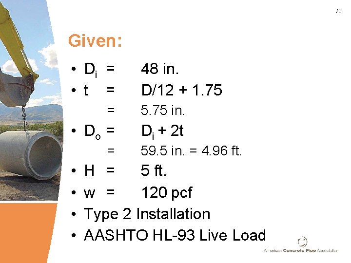
73 Given: • Di = • t = 48 in. D/12 + 1. 75 = 5. 75 in. • Do = Di + 2 t = • • 59. 5 in. = 4. 96 ft. H = 5 ft. w = 120 pcf Type 2 Installation AASHTO HL-93 Live Load
Soil Load www. concrete-pipe. org
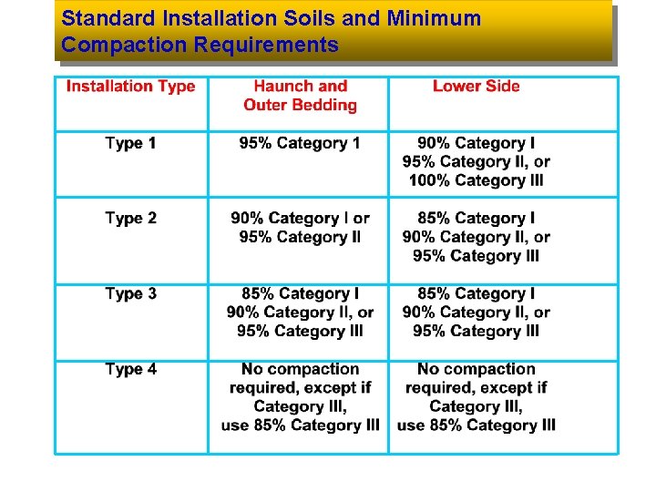
Standard Installation Soils and Minimum Compaction Requirements
76 AASHTO LRFD 12. 10. 2. 1 • WE = F e w B c H § § Fe = Soil-structure Interaction Factor w = unit weight of soil (pcf) Bc = outside diameter of pipe (ft) H = height of fill over the pipe (ft) www. concrete-pipe. org
77 AASHTO LRFD 12. 10. 2. 1 • “Standard installations for both embankments and trenches shall be designed for positive projection, embankment loading conditions where Fe shall be taken as the vertical arching factor, VAF, specified in Table 12. 10. 2. 1 -3 for each type of standard installation. ” www. concrete-pipe. org
78 AASHTO LRFD 12. 10. 2. 1
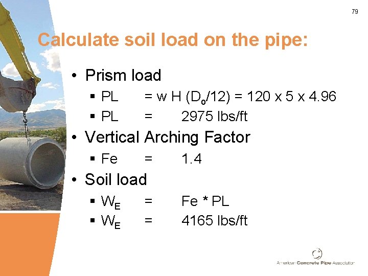
79 Calculate soil load on the pipe: • Prism load § PL = w H (Do/12) = 120 x 5 x 4. 96 = 2975 lbs/ft • Vertical Arching Factor § Fe = 1. 4 • Soil load § WE = = Fe * PL 4165 lbs/ft
Fluid Load www. concrete-pipe. org
81 AASHTO LRFD 12. 10. 2. 2 – Pipe Fluid Weight • “The unfactored weight of fluid, WF, in the pipe shall be considered in design based on a fluid weight of 62. 4 lb. /ft 3, unless otherwise specified. ” www. concrete-pipe. org
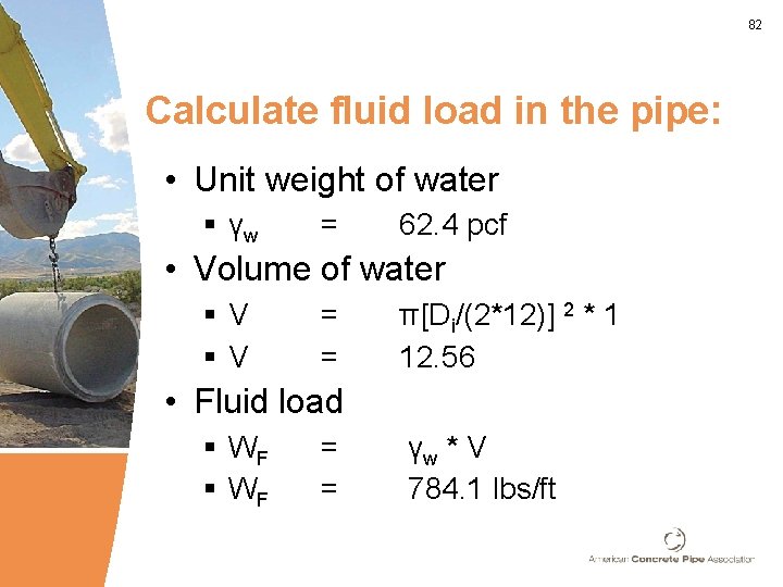
82 Calculate fluid load in the pipe: • Unit weight of water § γw = 62. 4 pcf • Volume of water §V §V = = π[Di/(2*12)] 2 * 1 12. 56 • Fluid load § WF = = γw * V 784. 1 lbs/ft
Live Load www. concrete-pipe. org
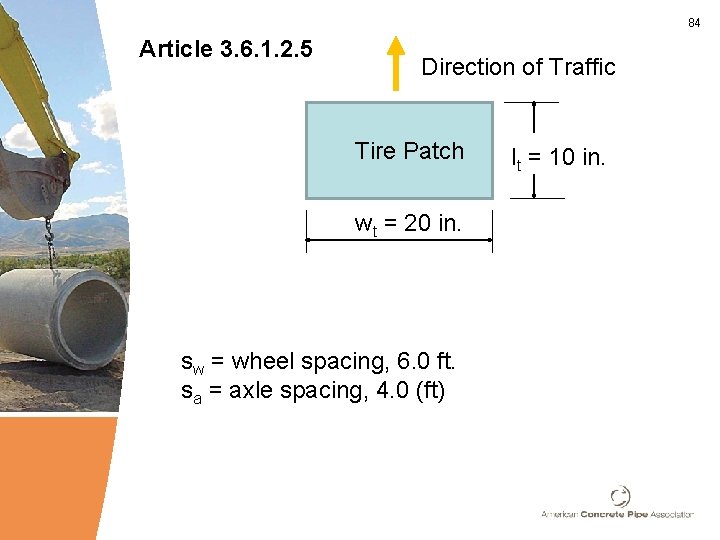
84 Article 3. 6. 1. 2. 5 Direction of Traffic Tire Patch wt = 20 in. sw = wheel spacing, 6. 0 ft. sa = axle spacing, 4. 0 (ft) lt = 10 in.
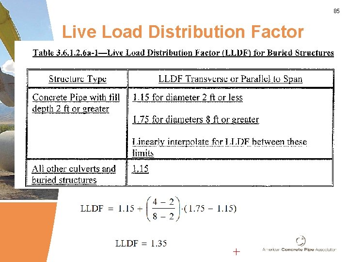
85 Live Load Distribution Factor
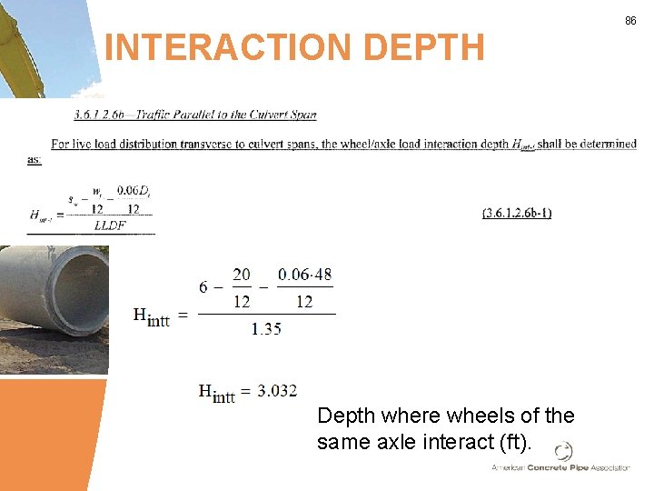
86 INTERACTION DEPTH Depth where wheels of the same axle interact (ft).
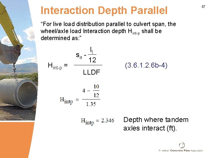
Interaction Depth Parallel “For live load distribution parallel to culvert span, the wheel/axle load Interaction depth Hint-p shall be determined as: ” Hint-p = lt sa 12 LLDF (3. 6. 1. 2. 6 b-4) Depth where tandem axles interact (ft). 87
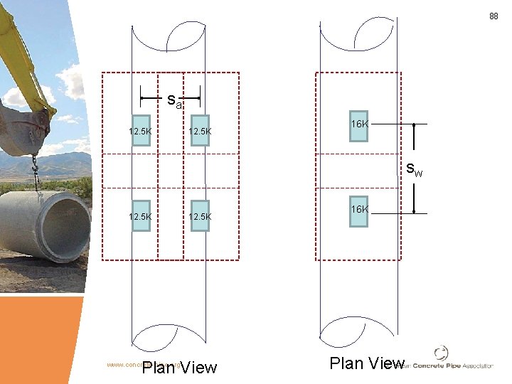
88 sa 12. 5 K 16 K sw 12. 5 K Plan View www. concrete-pipe. org 16 K Plan View

89 For the Axle Width Where H > Hint-t (3. 6. 1. 2. 6 b-3) Ww = wt/12 + sw + LLDF(H) + 0. 06(Di/12) Spread width of axle load at top of pipe (ft) www. concrete-pipe. org
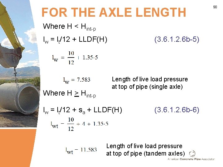
FOR THE AXLE LENGTH Where H < Hint-p lw = lt/12 + LLDF(H) Where H > Hint-p (3. 6. 1. 2. 6 b-5) Length of live load pressure at top of pipe (single axle) lw = lt/12 + sa + LLDF(H) (3. 6. 1. 2. 6 b-6) Length of live load pressure at top of pipe (tandem axles) 90
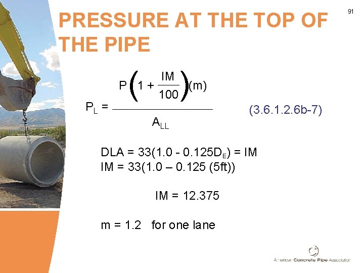
PRESSURE AT THE TOP OF THE PIPE PL = ( ) IM P 1+ (m) 100 ALL (3. 6. 1. 2. 6 b-7) DLA = 33(1. 0 - 0. 125 DE) = IM IM = 33(1. 0 – 0. 125 (5 ft)) IM = 12. 375 m = 1. 2 for one lane 91
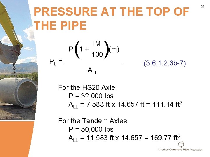
PRESSURE AT THE TOP OF THE PIPE PL = ( ) IM P 1+ (m) 100 ALL (3. 6. 1. 2. 6 b-7) For the HS 20 Axle P = 32, 000 lbs ALL = 7. 583 ft x 14. 657 ft = 111. 14 ft 2 For the Tandem Axles P = 50, 000 lbs ALL = 11. 583 ft x 14. 657 = 169. 77 ft 2 92
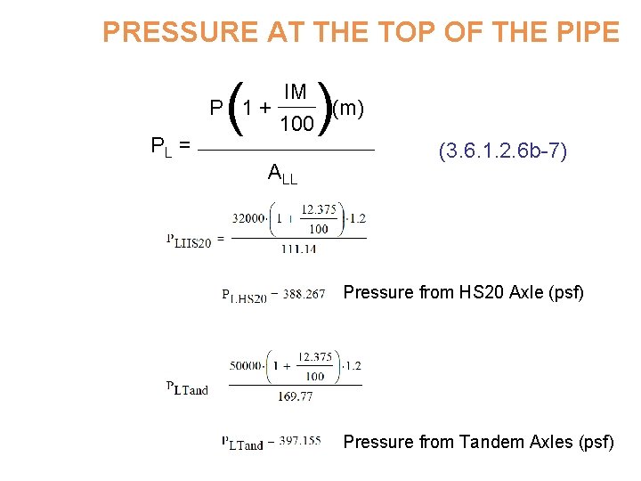
PRESSURE AT THE TOP OF THE PIPE PL = ( ) IM P 1+ (m) 100 ALL (3. 6. 1. 2. 6 b-7) Pressure from HS 20 Axle (psf) Pressure from Tandem Axles (psf)
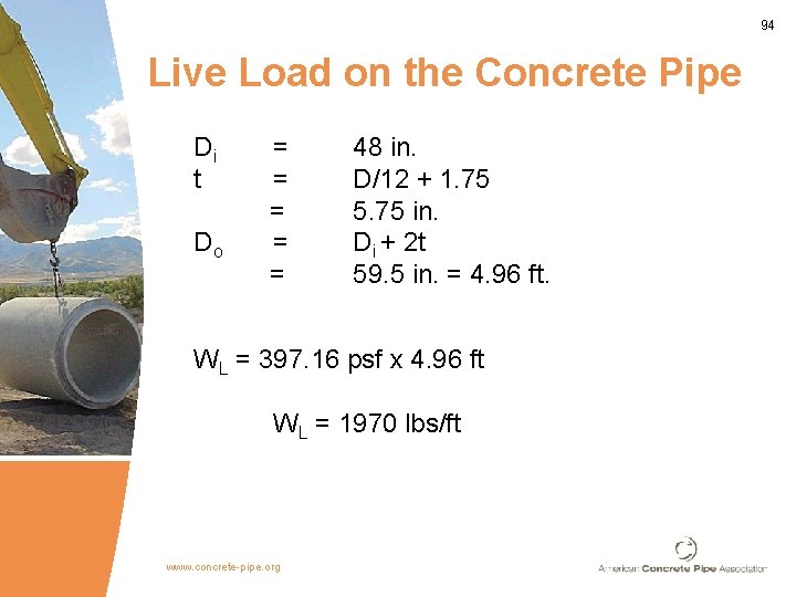
94 Live Load on the Concrete Pipe Di t Do = = = 48 in. D/12 + 1. 75 5. 75 in. Di + 2 t 59. 5 in. = 4. 96 ft. WL = 397. 16 psf x 4. 96 ft WL = 1970 lbs/ft www. concrete-pipe. org
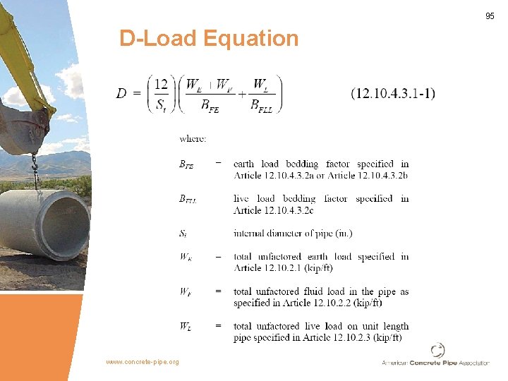
95 D-Load Equation www. concrete-pipe. org
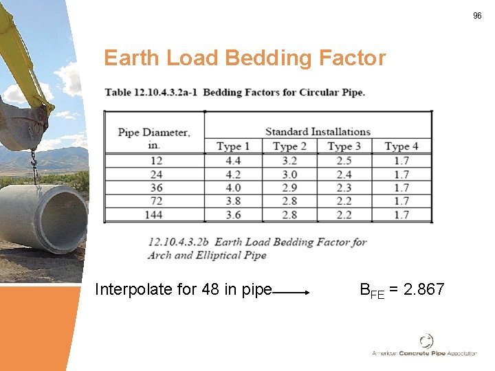
96 Earth Load Bedding Factor Interpolate for 48 in pipe BFE = 2. 867
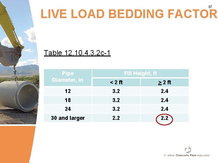
97 LIVE LOAD BEDDING FACTOR Table 12. 10. 4. 3. 2 c-1 Pipe Diameter, in Fill Height, ft < 2 ft > 2 ft 12 3. 2 2. 4 18 3. 2 2. 4 24 3. 2 2. 4 30 and larger 2. 2
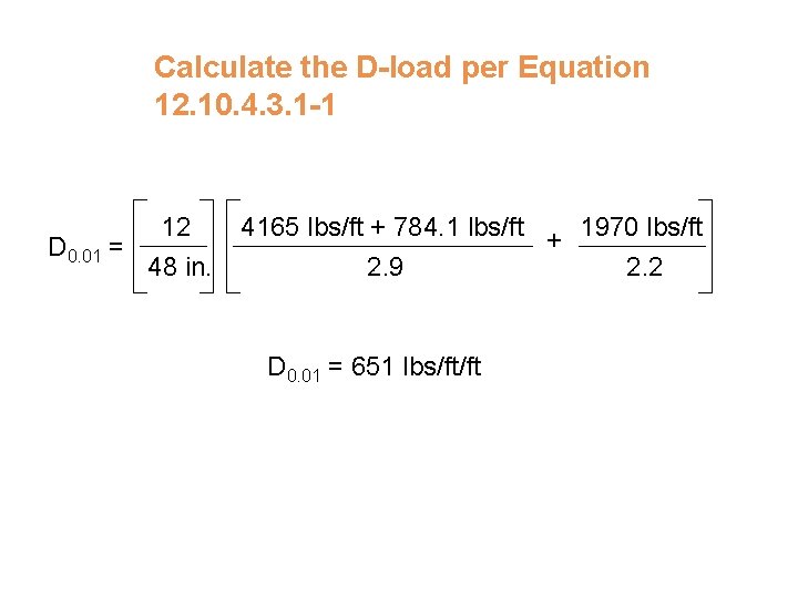
Calculate the D-load per Equation 12. 10. 4. 3. 1 -1 12 D 0. 01 = 48 in. 4165 lbs/ft + 784. 1 lbs/ft + 1970 lbs/ft 2. 9 2. 2 D 0. 01 = 651 lbs/ft/ft
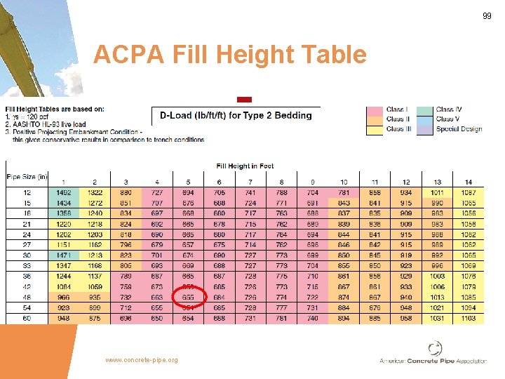
99 ACPA Fill Height Table www. concrete-pipe. org
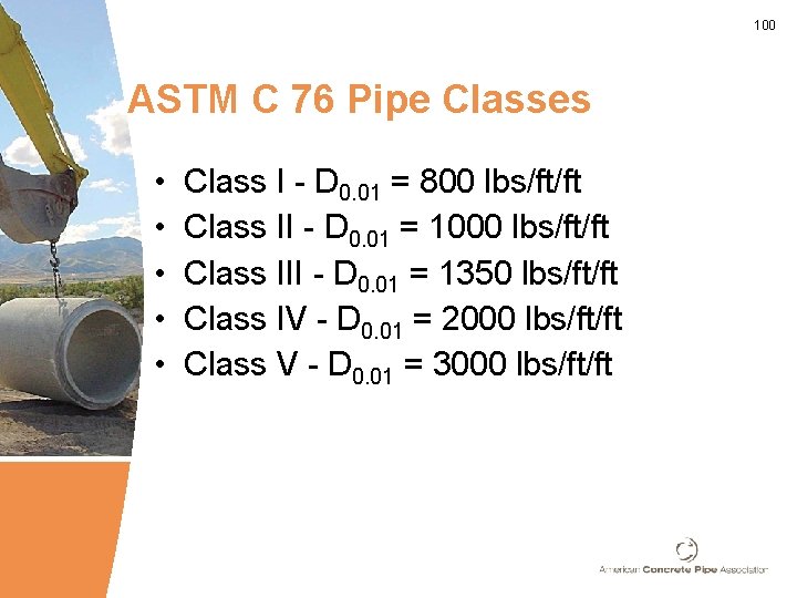
100 ASTM C 76 Pipe Classes • • • Class I - D 0. 01 = 800 lbs/ft/ft Class II - D 0. 01 = 1000 lbs/ft/ft Class III - D 0. 01 = 1350 lbs/ft/ft Class IV - D 0. 01 = 2000 lbs/ft/ft Class V - D 0. 01 = 3000 lbs/ft/ft
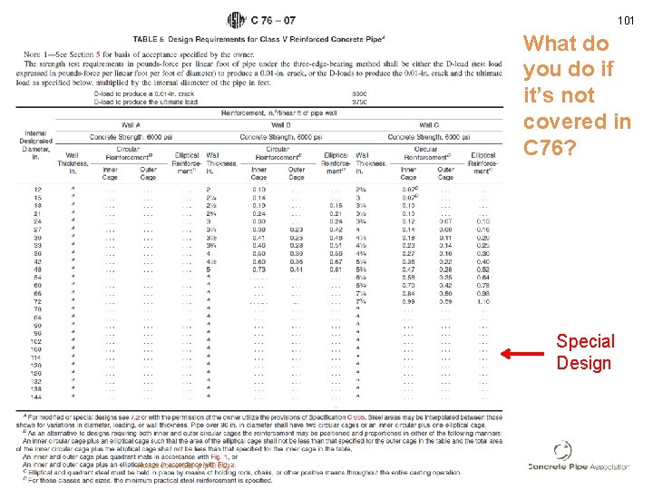
101 What do you do if it’s not covered in C 76? Special Design www. concrete-pipe. org
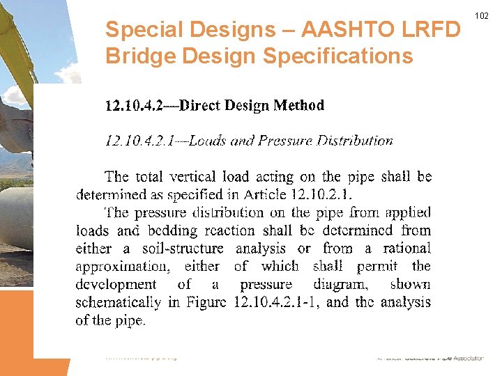
Special Designs – AASHTO LRFD Bridge Design Specifications www. concrete-pipe. org 102
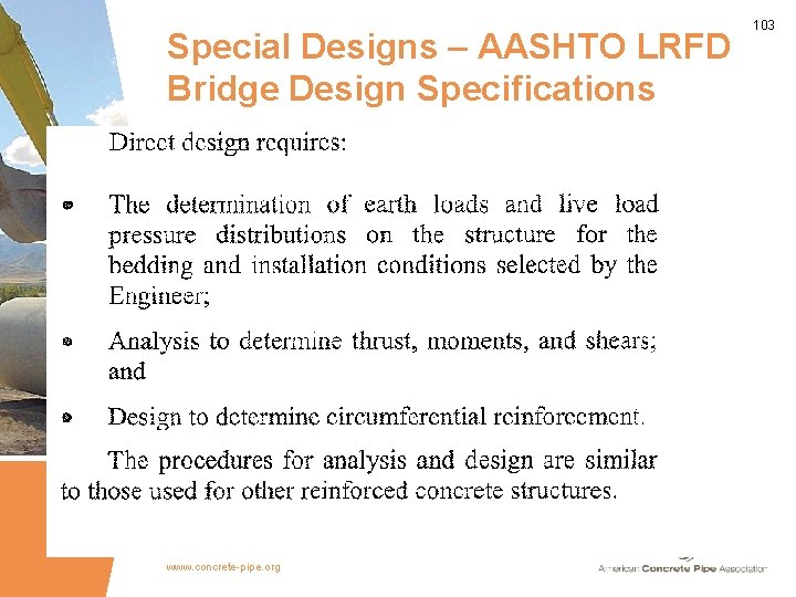
Special Designs – AASHTO LRFD Bridge Design Specifications www. concrete-pipe. org 103
The End www. concrete-pipe. org
- Slides: 104