
PRECAST CONCRETE COUPLED WALL SYSTEMS Brad Weldon Yahya

PRECAST CONCRETE COUPLED WALL SYSTEMS Brad Weldon Yahya C. (Gino) Kurama University of Notre Dame PCI Daniel P. Jenny Research Fellowship PCI Committee Days April 24, 2004
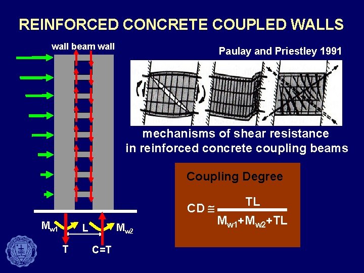
REINFORCED CONCRETE COUPLED WALLS wall beam wall Paulay and Priestley 1991 mechanisms of shear resistance in reinforced concrete coupling beams Coupling Degree CD Mw 1 Mw 2 L T C=T TL Mw 1+Mw 2+TL
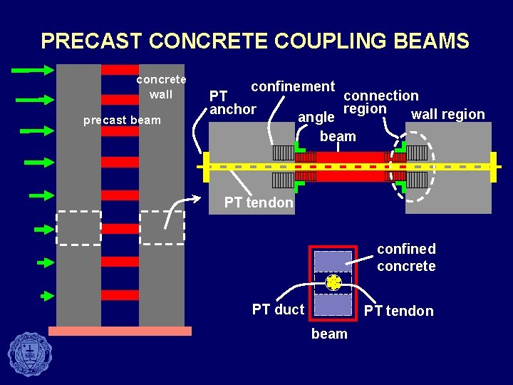
PRECAST CONCRETE COUPLING BEAMS concrete wall precast beam confinement PT anchor connection region wall region angle beam PT tendon confined concrete PT duct PT tendon beam
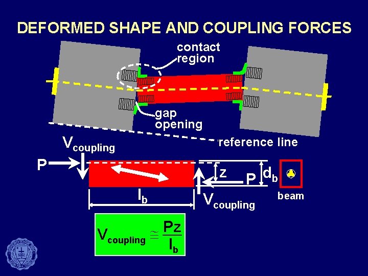
DEFORMED SHAPE AND COUPLING FORCES contact region gap opening Vcoupling reference line P z lb Vcoupling P db Vcoupling @ Pz lb beam
OBJECTIVES • Develop new system based on experimental and analytical studies • Develop seismic design/analysis guidelines and tools, and recommendations for application
OUTLINE • Steel Coupling Beams § Experimental program § Analytical model and verification • Precast Coupling Beams § Advantages § Parametric studies (DRAIN-2 DX) § Design approach
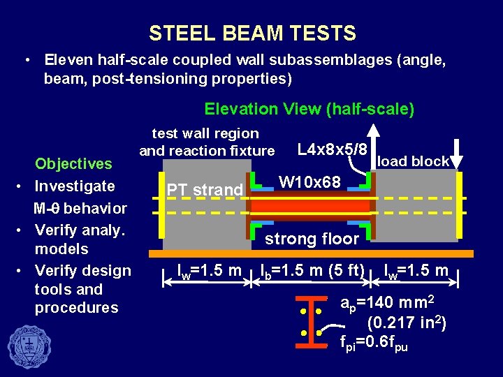
STEEL BEAM TESTS • Eleven half-scale coupled wall subassemblages (angle, beam, post-tensioning properties) Elevation View (half-scale) Objectives • Investigate M-q behavior • Verify analy. models • Verify design tools and procedures test wall region and reaction fixture PT strand L 4 x 8 x 5/8 load block W 10 x 68 strong floor lw=1. 5 m lb=1. 5 m (5 ft) lw=1. 5 m ap=140 mm 2 (0. 217 in 2) fpi=0. 6 fpu
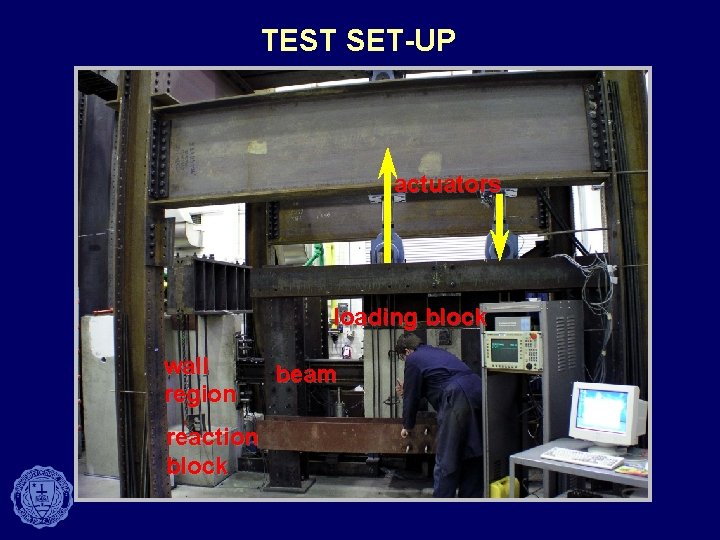
TEST SET-UP actuators loading block wall region reaction block beam

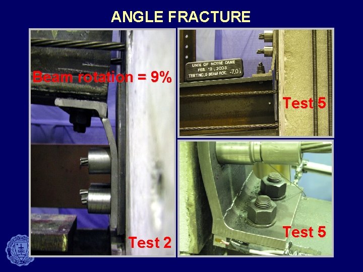
ANGLE FRACTURE Beam rotation = 9% Test 5 Test 2 Test 5
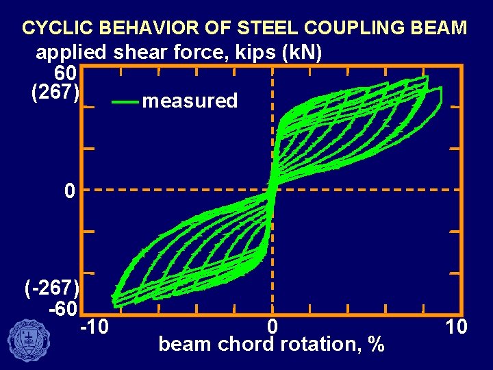
CYCLIC BEHAVIOR OF STEEL COUPLING BEAM applied shear force, kips (k. N) 60 (267) measured 0 (-267) -60 -10 0 beam chord rotation, % 10
ANALYTICAL WALL MODEL (DRAIN-2 DX)
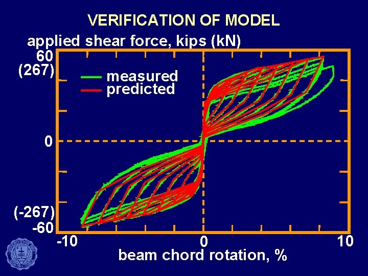
VERIFICATION OF MODEL applied shear force, kips (k. N) 60 (267) measured predicted 0 (-267) -60 -10 0 beam chord rotation, % 10
POST-TENSIONED COUPLED WALLS • Unbonded post-tensioning is a promising and feasible method to couple concrete walls (up to 60 -65 percent coupling) • Large self-centering, considerable energy dissipation • Large deformations with little damage • The analytical models and design tools/procedures work well • Shift focus towards precast beams
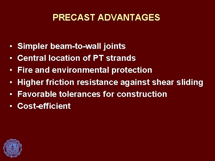
PRECAST ADVANTAGES • • • Simpler beam-to-wall joints Central location of PT strands Fire and environmental protection Higher friction resistance against shear sliding Favorable tolerances for construction Cost-efficient
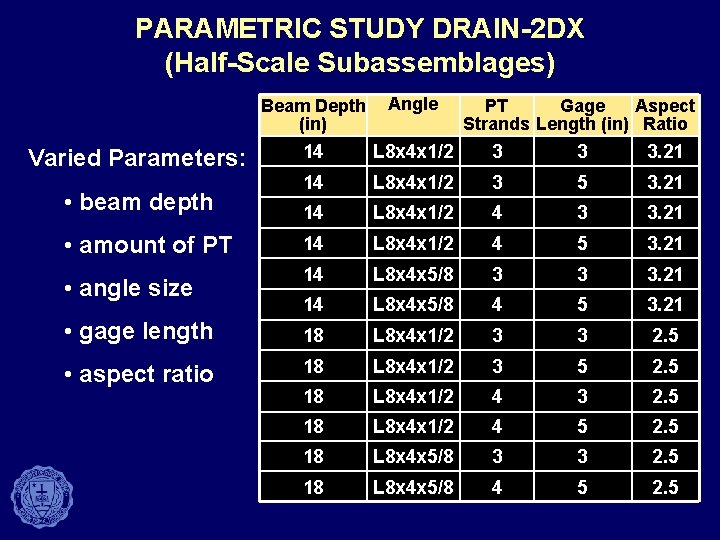
PARAMETRIC STUDY DRAIN-2 DX (Half-Scale Subassemblages) Beam Depth (in) Angle 14 L 8 x 4 x 1/2 3 3 3. 21 14 L 8 x 4 x 1/2 3 5 3. 21 14 L 8 x 4 x 1/2 4 3 3. 21 14 L 8 x 4 x 1/2 4 5 3. 21 14 L 8 x 4 x 5/8 3 3 3. 21 14 L 8 x 4 x 5/8 4 5 3. 21 • gage length 18 L 8 x 4 x 1/2 3 3 2. 5 • aspect ratio 18 L 8 x 4 x 1/2 3 5 2. 5 18 L 8 x 4 x 1/2 4 3 2. 5 18 L 8 x 4 x 1/2 4 5 2. 5 18 L 8 x 4 x 5/8 3 3 2. 5 18 L 8 x 4 x 5/8 4 5 2. 5 Varied Parameters: • beam depth • amount of PT • angle size PT Gage Aspect Strands Length (in) Ratio
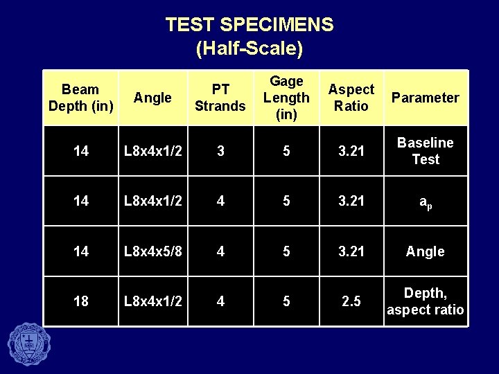
TEST SPECIMENS (Half-Scale) Angle PT Strands Gage Length (in) Aspect Ratio Parameter 14 L 8 x 4 x 1/2 3 5 3. 21 Baseline Test 14 L 8 x 4 x 1/2 4 5 3. 21 ap 14 L 8 x 4 x 5/8 4 5 3. 21 Angle 18 L 8 x 4 x 1/2 4 5 2. 5 Depth, aspect ratio Beam Depth (in)
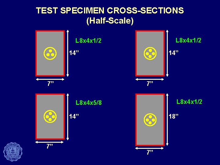
TEST SPECIMEN CROSS-SECTIONS (Half-Scale) L 8 x 4 x 1/2 14” 7” L 8 x 4 x 1/2 L 8 x 4 x 5/8 14” 7” 18” 7”
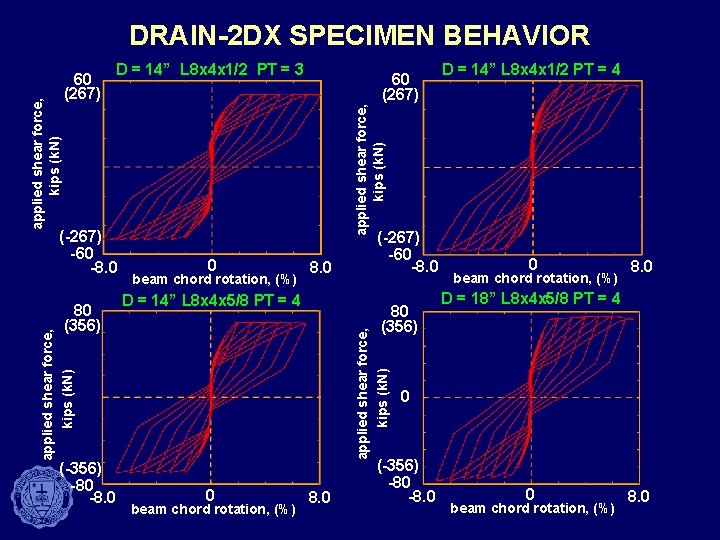
D = 14” L 8 x 4 x 1/2 PT = 3 (-267) -60 -8. 0 0 beam chord rotation, (%) 8. 0 D = 14” L 8 x 4 x 5/8 PT = 4 (-356) -80 -8. 0 (-267) -60 -8. 0 80 (356) applied shear force, kips (k. N) 80 (356) 60 (267) D = 14” L 8 x 4 x 1/2 PT = 4 applied shear force, kips (k. N) 60 (267) applied shear force, kips (k. N) DRAIN-2 DX SPECIMEN BEHAVIOR 0 beam chord rotation, (%) 8. 0 D = 18” L 8 x 4 x 5/8 PT = 4 0 (-356) -80 -8. 0 0 beam chord rotation, (%) 8. 0
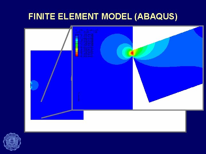
FINITE ELEMENT MODEL (ABAQUS)
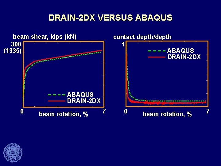
DRAIN-2 DX VERSUS ABAQUS beam shear, kips (k. N) 300 (1335) contact depth/depth 1 ABAQUS DRAIN-2 DX 0 beam rotation, % 7
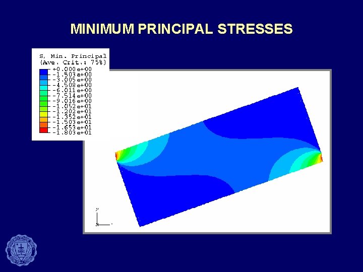
MINIMUM PRINCIPAL STRESSES
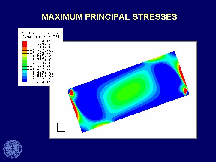
MAXIMUM PRINCIPAL STRESSES
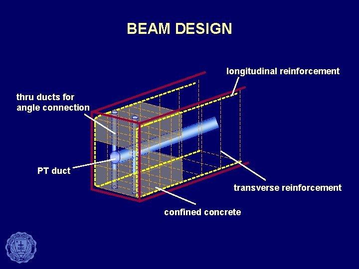
BEAM DESIGN longitudinal reinforcement thru ducts for angle connection PT duct transverse reinforcement confined concrete
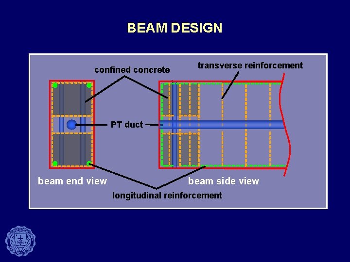
BEAM DESIGN confined concrete transverse reinforcement PT duct beam end view beam side view longitudinal reinforcement
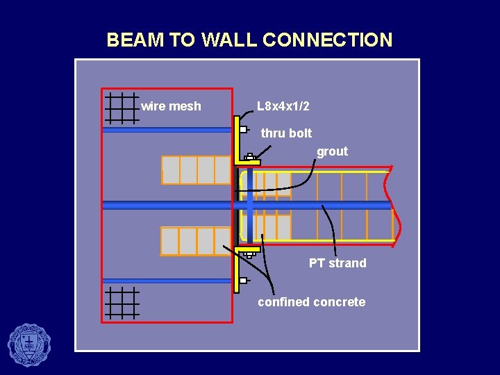
BEAM TO WALL CONNECTION wire mesh L 8 x 4 x 1/2 thru bolt grout PT strand confined concrete

CURRENT STATUS • Finalizing design • Laboratory set-up • Begin testing this summer

ACKNOWLEDGMENTS • Precast/Prestressed Concrete Institute • University of Notre Dame Industry Participants • Cary Kopczynski & Company • Stres. Core Inc. • Dywidag Systems International, U. S. A, Inc. • Insteel Wire Products • Dayton/Richmond Concrete Accessories

- Slides: 29