
Practical Aspects of Crystallization in High Level Nuclear

- Slides: 20
Practical Aspects of Crystallization in High Level Nuclear Waste Glasses Kevin M. Fox, D. L. Mc. Clane, J. W. Amoroso, M. D. Fowley, and D. H. Miller Albert A. Kruger U. S. Department of Energy – Office of River Protection PACRIM 12 May 24, 2017 SRNL-STI-2016 -00643 -S
Acknowledgements • Andy Foreman, Michael Restivo, Vernon Bush, Jon Duvall, Kenn Gibbs, Monica Phillips, and Erich Hansen at SRNL • Josef Matyáš, Mike Schweiger, David Peeler, and John Vienna at PNNL • Funding by the DOE-ORP Waste Treatment & Immobilization Plant Project, William F. Hamel, Jr. , Federal Project Director, is gratefully acknowledged. 2
Introduction • US DOE safely immobilizes defense high level nuclear waste in borosilicate glass using Joule heated, ceramic lined melters • Tailored glass formulations are used to improve loading of waste in glass product – Crystallization can limit access to higher waste loading • Impacts of crystallization depend on the type of crystal – Spinels do not impact the performance of the waste form, but can be problematic in a melter – Nepheline reduces chemical durability of the glass, and tends to form during cooling in the canister • Approaches for tolerating crystallization are needed to further increase waste loading in glass – Allow a controlled amount of spinel crystals in melter – Recover from unintended spinel accumulation – Understand nepheline crystallization and its true impacts 3
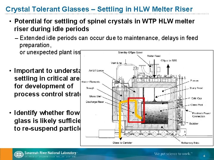
Crystal Tolerant Glasses – Settling in HLW Melter Riser • Potential for settling of spinel crystals in WTP HLW melter riser during idle periods – Extended idle periods can occur due to maintenance, delays in feed preparation, or unexpected plant issues • Important to understand settling in critical areas for development of process control strategy • Identify whether flow of glass is likely sufficient to re-suspend particles 4
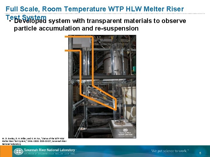
Full Scale, Room Temperature WTP HLW Melter Riser Test System • Developed system with transparent materials to observe particle accumulation and re-suspension M. D. Fowley, D. H. Miller, and K. M. Fox, “Status of the WTP HLW Melter Riser Test System, ” SRNL-L 3000 -2015 -00017, Savannah River National Laboratory 5
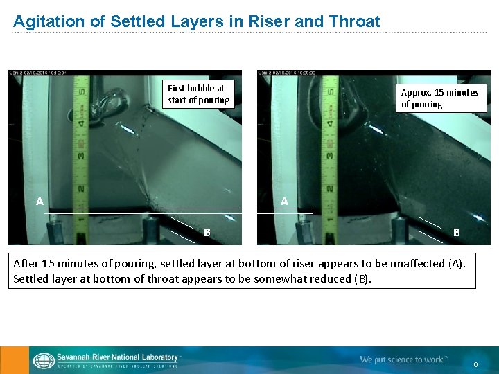
Agitation of Settled Layers in Riser and Throat First bubble at start of pouring A Approx. 15 minutes of pouring A B B After 15 minutes of pouring, settled layer at bottom of riser appears to be unaffected (A). Settled layer at bottom of throat appears to be somewhat reduced (B). 6
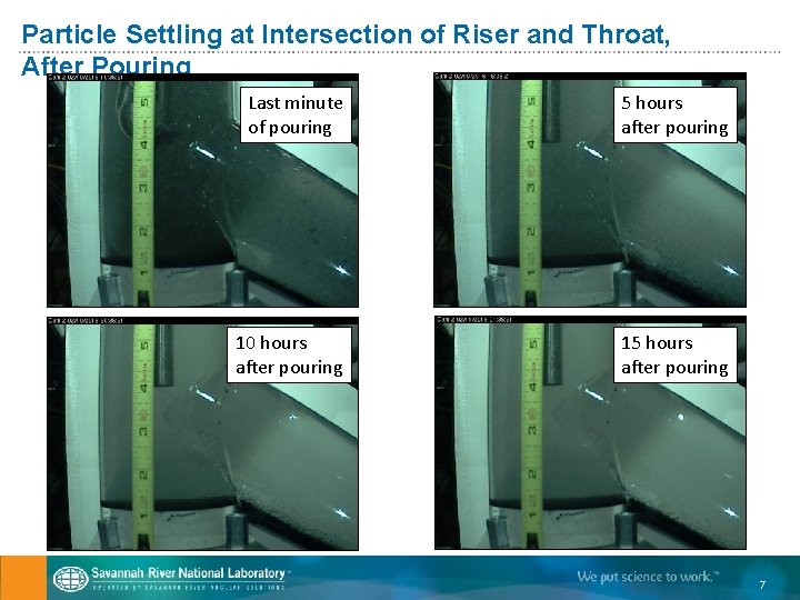
Particle Settling at Intersection of Riser and Throat, After Pouring Last minute of pouring 5 hours after pouring 10 hours after pouring 15 hours after pouring 7
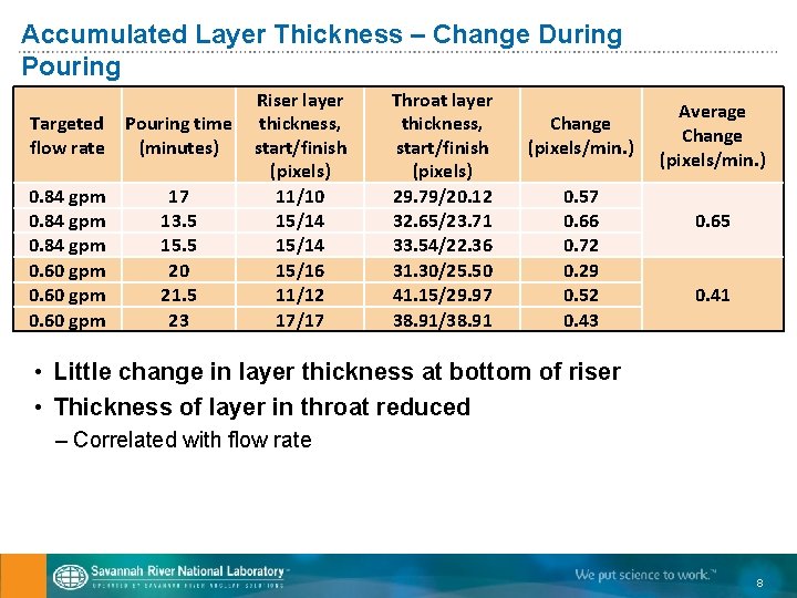
Accumulated Layer Thickness – Change During Pouring Targeted flow rate Pouring time (minutes) 0. 84 gpm 0. 60 gpm 17 13. 5 15. 5 20 21. 5 23 Riser layer thickness, start/finish (pixels) 11/10 15/14 15/16 11/12 17/17 Throat layer thickness, start/finish (pixels) 29. 79/20. 12 32. 65/23. 71 33. 54/22. 36 31. 30/25. 50 41. 15/29. 97 38. 91/38. 91 Change (pixels/min. ) 0. 57 0. 66 0. 72 0. 29 0. 52 0. 43 Average Change (pixels/min. ) 0. 65 0. 41 • Little change in layer thickness at bottom of riser • Thickness of layer in throat reduced – Correlated with flow rate 8
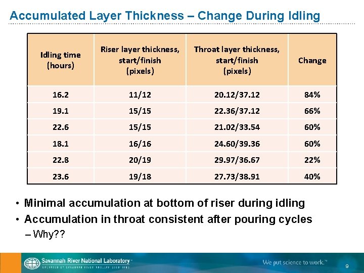
Accumulated Layer Thickness – Change During Idling time (hours) Riser layer thickness, start/finish (pixels) Throat layer thickness, start/finish (pixels) Change 16. 2 11/12 20. 12/37. 12 84% 19. 1 15/15 22. 36/37. 12 66% 22. 6 15/15 21. 02/33. 54 60% 18. 1 16/16 24. 60/39. 36 60% 22. 8 20/19 29. 97/36. 67 22% 23. 6 19/18 27. 73/38. 91 40% • Minimal accumulation at bottom of riser during idling • Accumulation in throat consistent after pouring cycles – Why? ? 9
Observations and Future Work – Particle Resuspension • Accumulated layers seem to have reached stable thickness after multiple pouring cycles • Further experiments designed to better understand flow patterns and settling during idle periods • Identify impact of temporary facility changes, such as lowering air lance, on ability to resuspend settled particles 10
Spinel Dissolution – Recovery from Excess Accumulation • Off-normal operating conditions may cause undesirable accumulations of spinel crystals in a melter – Feed outages, unplanned maintenance, etc. • Method for recovering full throughput of melter is desirable as part of a crystal tolerant approach • Demonstrated dissolution of accumulated spinel crystals in conditions similar to bubbled melter – Bench scale testing in platinum crucible with bubbler – Tailored addition of glass forming chemicals – Maintain acceptable glass processing properties and waste form performance 11
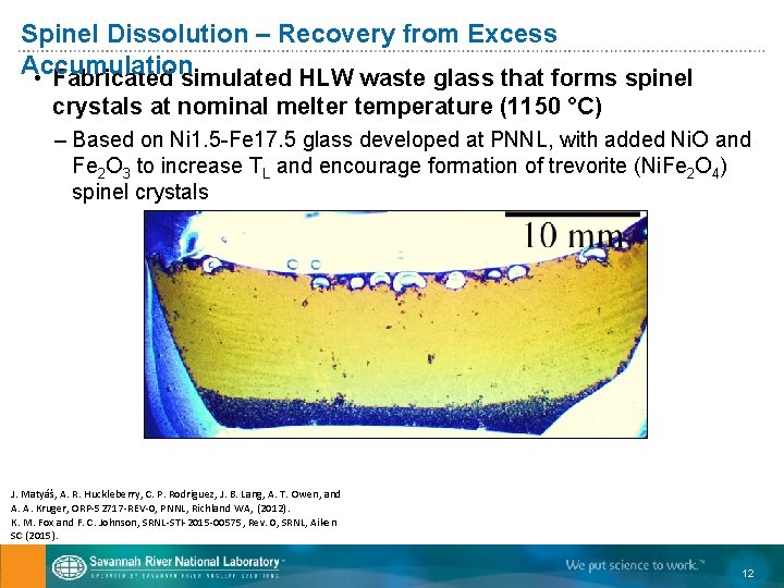
Spinel Dissolution – Recovery from Excess Accumulation • Fabricated simulated HLW waste glass that forms spinel crystals at nominal melter temperature (1150 °C) – Based on Ni 1. 5 -Fe 17. 5 glass developed at PNNL, with added Ni. O and Fe 2 O 3 to increase TL and encourage formation of trevorite (Ni. Fe 2 O 4) spinel crystals J. Matyáš, A. R. Huckleberry, C. P. Rodriguez, J. B. Lang, A. T. Owen, and A. A. Kruger, ORP-52717 -REV-0, PNNL, Richland WA, (2012). K. M. Fox and F. C. Johnson, SRNL-STI-2015 -00575, Rev. 0, SRNL, Aiken SC (2015). 12
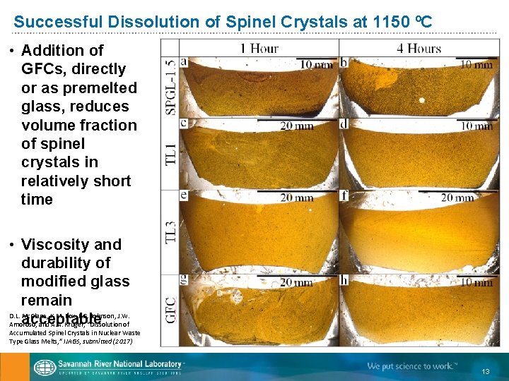
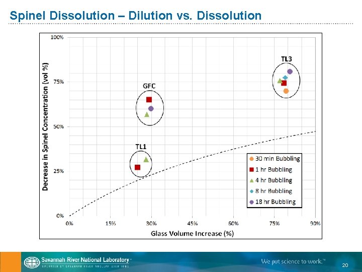
Successful Dissolution of Spinel Crystals at 1150 ºC • Addition of GFCs, directly or as premelted glass, reduces volume fraction of spinel crystals in relatively short time • Viscosity and durability of modified glass remain D. L. Mc. Clane, K. M. Fox, F. C. Johnson, J. W. acceptable Amoroso, and A. A. Kruger, “Dissolution of Accumulated Spinel Crystals in Nuclear Waste Type Glass Melts, ” IJAGS, submitted (2017) 13
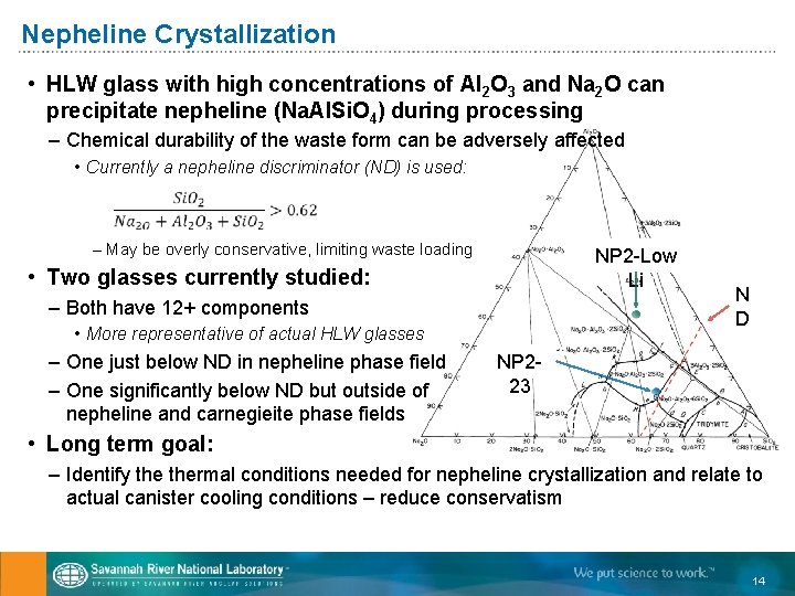
Nepheline Crystallization • HLW glass with high concentrations of Al 2 O 3 and Na 2 O can precipitate nepheline (Na. Al. Si. O 4) during processing – Chemical durability of the waste form can be adversely affected • Currently a nepheline discriminator (ND) is used: – May be overly conservative, limiting waste loading NP 2 -Low Li • Two glasses currently studied: – Both have 12+ components • More representative of actual HLW glasses – One just below ND in nepheline phase field – One significantly below ND but outside of nepheline and carnegieite phase fields N D NP 223 • Long term goal: – Identify thermal conditions needed for nepheline crystallization and relate to actual canister cooling conditions – reduce conservatism 14
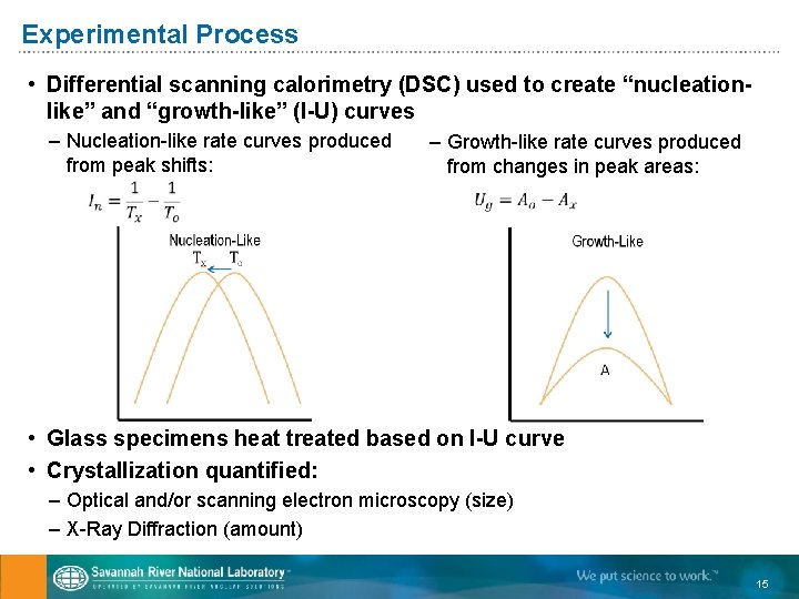
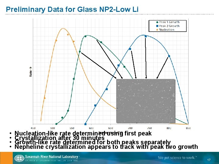
Experimental Process • Differential scanning calorimetry (DSC) used to create “nucleationlike” and “growth-like” (I-U) curves – Nucleation-like rate curves produced from peak shifts: – Growth-like rate curves produced from changes in peak areas: • Glass specimens heat treated based on I-U curve • Crystallization quantified: – Optical and/or scanning electron microscopy (size) – X-Ray Diffraction (amount) 15
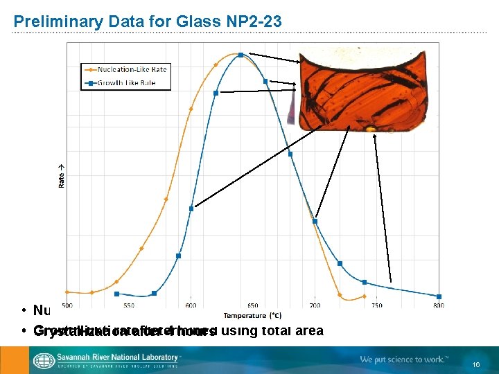
Preliminary Data for Glass NP 2 -23 • Nucleation-like rate determined using first peak • Growth-like rateafter determined Crystallization 4 hours using total area 16
Preliminary Data for Glass NP 2 -Low Li • • Nucleation-like rate determined using first peak Crystallization after 30 minutes Growth-like rate determined for both peaks separately Nepheline crystallization appears to track with peak two growth 17
Summary • Full-scale, transparent system developed to identify crystal flow and settling in WTP HLW melter – Results will be used to better understand implementation of crystal tolerant approach to glass production • Accumulated spinel crystals can be dissolved at 1150 °C using a tailored addition of glass forming chemicals – Modified glass remains acceptable for melter processing and repository disposal • Differential scanning calorimetry utilized to produce nucleation-like and growth-like curves for nepheline in simulated HLW glasses – Data will be combined with thermal model to determine amount of nepheline likely to form during glass cooling in canister 18
Extra slides 19
Spinel Dissolution – Dilution vs. Dissolution 20