
PPK Mekatronik Uni MAP ENT 364 Control System





- Slides: 48
PPK Mekatronik, Uni. MAP ENT 364: Control System Root Locus
Overview n Introduction n Defining the Root Locus n Properties of the Root Locus n Sketching the Root Locus n Refining the Sketch n An Example n Transient Response Design via Gain Adjustment n Generalized Root Locus n Root Locus for Positive-Feedback Systems n Pole Sensitivity 2
Objectives n Definition of a root locus n How to sketch a root locus n How to refine your sketch of a root locus n How to use the root locus to find the poles of a closed -loop system n How to use the root locus to describe qualitatively the changes in transient response and stability of a system as a system parameter is varied n How to use the root locus to design a parameter value to meet a transient response specification for systems of order 2 and higher 3
Introduction n What is root locus? n n Root locus is a graphical representation of the closedloop poles as a system parameter is varied It can be used to describe qualitatively the performance of a system as various parameters are changed It gives graphic representation of a system’s transient response and also stability We can see the range of stability, instability, and the conditions that cause a system to break into oscillation 4
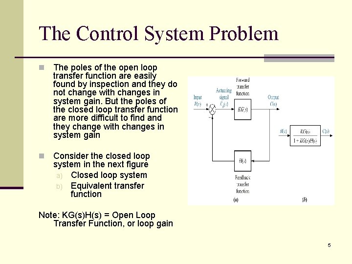
The Control System Problem n The poles of the open loop transfer function are easily found by inspection and they do not change with changes in system gain. But the poles of the closed loop transfer function are more difficult to find and they change with changes in system gain n Consider the closed loop system in the next figure a) Closed loop system b) Equivalent transfer function Note: KG(s)H(s) = Open Loop Transfer Function, or loop gain 5
If n Observations: n G(s) = NG(s) / DG(s) n And H(s) = NH(s) / DH(s) n Then T(s) = KG(s) / 1 + K(s)H(s) Therefore T(s) = KNG(s)DH(s) / DG(s)DH(s) + KNG(s)NH(s) n The zero of T(s) consist of the zeros of G(s) and The poles of H(s) The poles of T(s) are not immediately known without factoring the denominator and they are a function of K Since the system’s performance depends on the knowledge of the poles’ location, we will not be able to know the system performance readily Root locus can be used to give us a picture of the poles of T(s) as the system gain, K, Varies 6
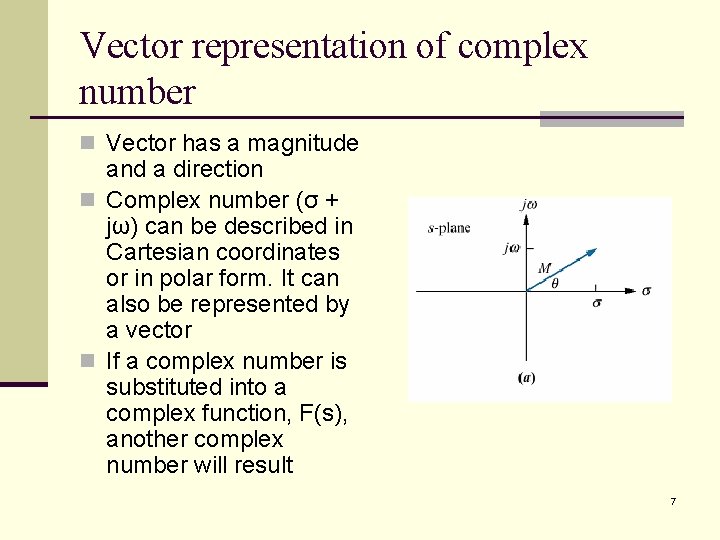
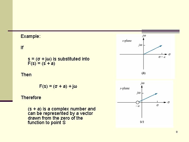
Vector representation of complex number n Vector has a magnitude and a direction n Complex number (σ + jω) can be described in Cartesian coordinates or in polar form. It can also be represented by a vector n If a complex number is substituted into a complex function, F(s), another complex number will result 7
Example: If s = (σ + jω) is substituted into F(s) = (s + a) Then F(s) = (σ + a) + jω Therefore (s + a) is a complex number and can be represented by a vector drawn from the zero of the function to point S 8
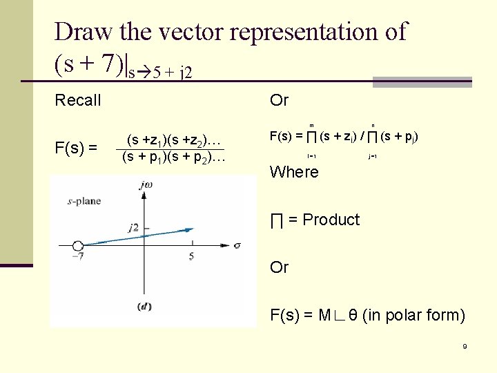
Draw the vector representation of (s + 7)|s 5 + j 2 Recall Or m F(s) = (s +z 1)(s +z 2)… (s + p 1)(s + p 2)… n F(s) = ∏ (s + zi) / ∏ (s + pj) I =1 j =1 Where ∏ = Product Or F(s) = M∟θ (in polar form) 9
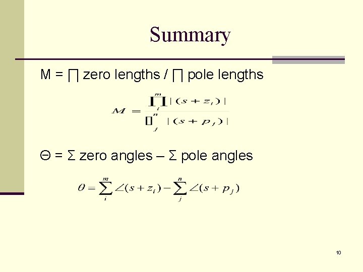
Summary M = ∏ zero lengths / ∏ pole lengths Θ = Σ zero angles – Σ pole angles 10
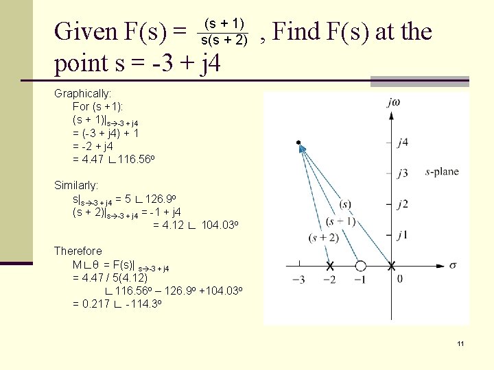
(s + 1) s(s + 2) Given F(s) = point s = -3 + j 4 , Find F(s) at the Graphically: For (s +1): (s + 1)|s -3 + j 4 = (-3 + j 4) + 1 = -2 + j 4 = 4. 47 ∟ 116. 56 o Similarly: s|s -3 + j 4 = 5 ∟ 126. 9 o (s + 2)|s -3 + j 4 = -1 + j 4 = 4. 12 ∟ 104. 03 o Therefore M∟θ = F(s)| s -3 + j 4 = 4. 47 / 5(4. 12) ∟ 116. 56 o – 126. 9 o +104. 03 o = 0. 217 ∟ -114. 3 o 11
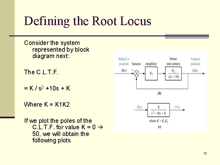
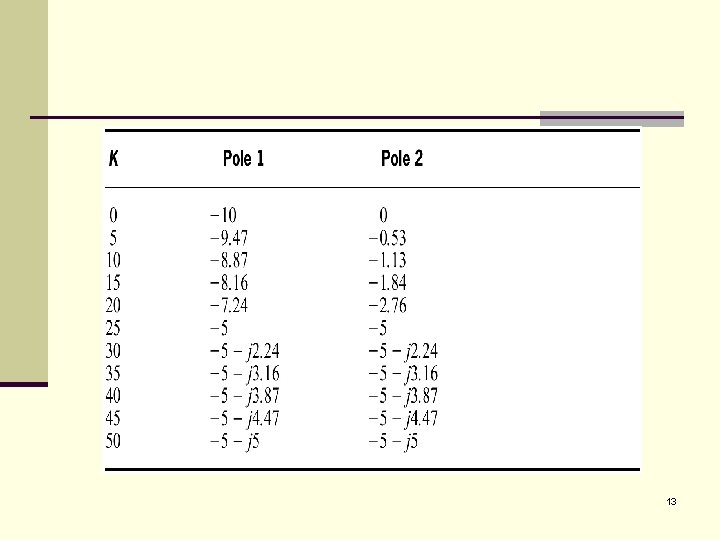
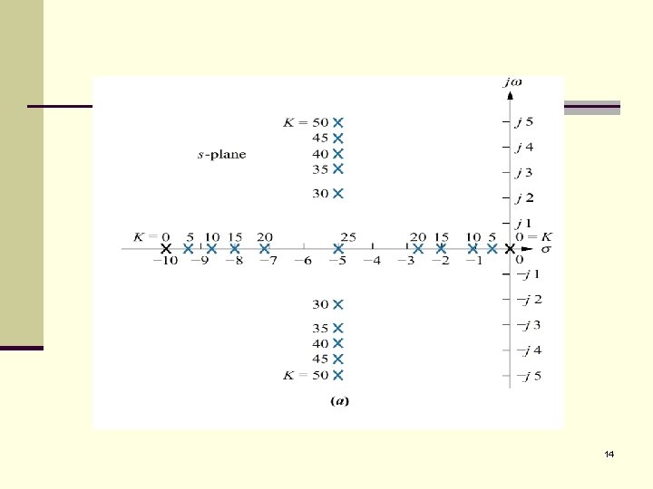
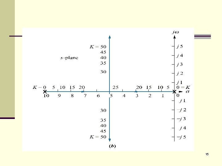
Defining the Root Locus Consider the system represented by block diagram next: The C. L. T. F. = K / s 2 +10 s + K Where K = K 1 K 2 If we plot the poles of the C. L. T. F. for value K = 0 50, we will obtain the following plots 12
13
14
15
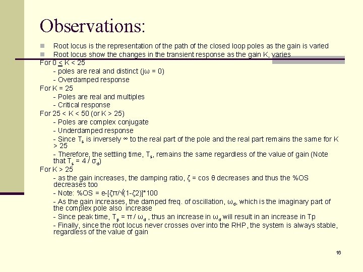
Observations: Root locus is the representation of the path of the closed loop poles as the gain is varied Root locus show the changes in the transient response as the gain K, varies For 0 < K < 25 - poles are real and distinct (jω = 0) - Overdamped response For K = 25 - Poles are real and multiples - Critical response For 25 < K < 50 (or K > 25) - Poles are complex conjugate - Underdamped response - Since Ts is inversely ∞ to the real part of the pole and the real part remains the same for K > 25 - Therefore, the settling time, Ts, remains the same regardless of the value of gain (Note that Ts = 4 / σd) For K > 25 - as the gain increases, the damping ratio, ζ = cos θ decreases and thus the %OS decreases too - Note: %OS = e-[ζπ/√(1 -ζ 2)]*100 - As the gain increases, the damped freq. of oscillation, ωd, which is the imaginary part of the complex pole also increase - Since peak time, Tp = π / ωd , thus an increase in ωd will result in an increase in Tp - Finally, since the root locus never crosses over into the RHP, the system is always stable, regardless of the value of gain n n 16
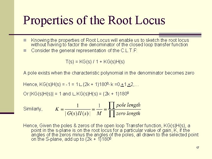
Properties of the Root Locus Knowing the properties of Root Locus will enable us to sketch the root locus without having to factor the denominator of the closed loop transfer function n Consider the general representation of the C. L. T. F: n T(s) = KG(s) / 1 + KG(s)H(s) A pole exists when the characteristic polynomial in the denominator becomes zero Hence, KG(s)H(s) = -1 = 1∟(2 k + 1)1800, k =0, +1, +2, … Or |KG(s)H(s)| = 1 and ∟KG(s)H(s) = (2 k + 1)1800 Similarly, Hence, Given the poles & zeros of the open loop Transfer function, KG(s)H(s), a point in the s-plane is on the root locus for a particular value of gain, K, if the angles of the zeros minus the angles of the poles, all drawn to the selected point on the S-plane, add up to (2 k + 1)1800 17
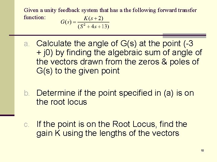
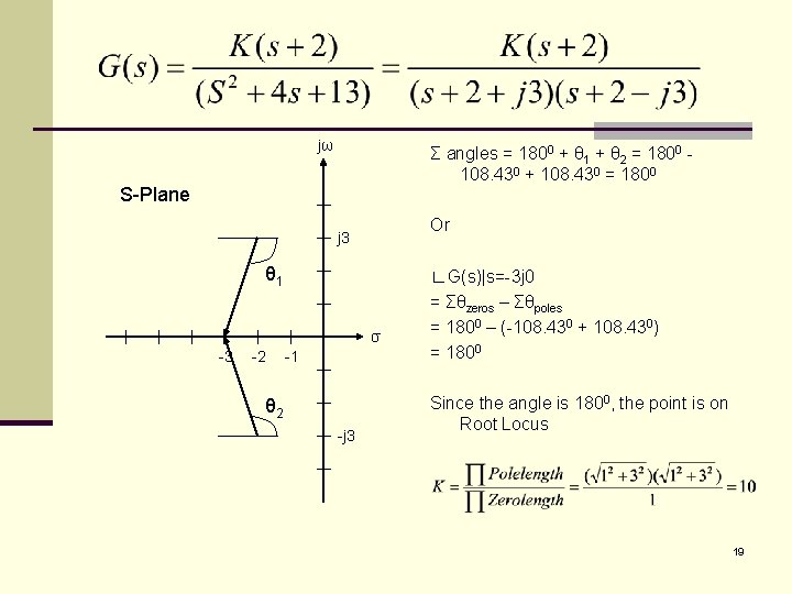
Given a unity feedback system that has a the following forward transfer function: a. Calculate the angle of G(s) at the point (-3 + j 0) by finding the algebraic sum of angle of the vectors drawn from the zeros & poles of G(s) to the given point b. Determine if the point specified in (a) is on the root locus c. If the point is on the Root Locus, find the gain K using the lengths of the vectors 18
jω Σ angles = 1800 + θ 1 + θ 2 = 1800 108. 430 + 108. 430 = 1800 S-Plane Or j 3 θ 1 σ -3 -2 -1 θ 2 -j 3 ∟G(s)|s=-3 j 0 = Σθzeros – Σθpoles = 1800 – (-108. 430 + 108. 430) = 1800 Since the angle is 1800, the point is on Root Locus 19
Sketching the Root Locus n Based on the properties of root locus, some rules are established to enable us to sketch the Root Locus: Symmetry Number of Branches Real Axis segment RULES Starting & Ending Point Behavior at infinity 20
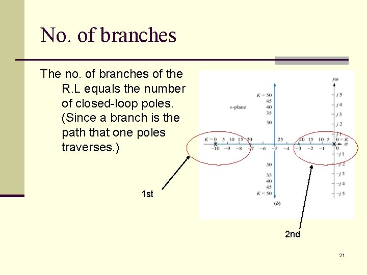
No. of branches The no. of branches of the R. L equals the number of closed-loop poles. (Since a branch is the path that one poles traverses. ) 1 st 2 nd 21
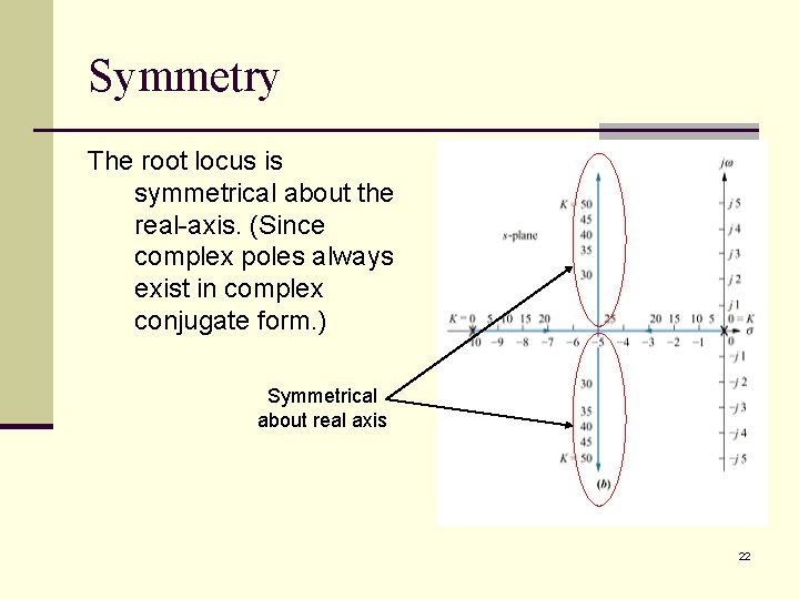
Symmetry The root locus is symmetrical about the real-axis. (Since complex poles always exist in complex conjugate form. ) Symmetrical about real axis 22
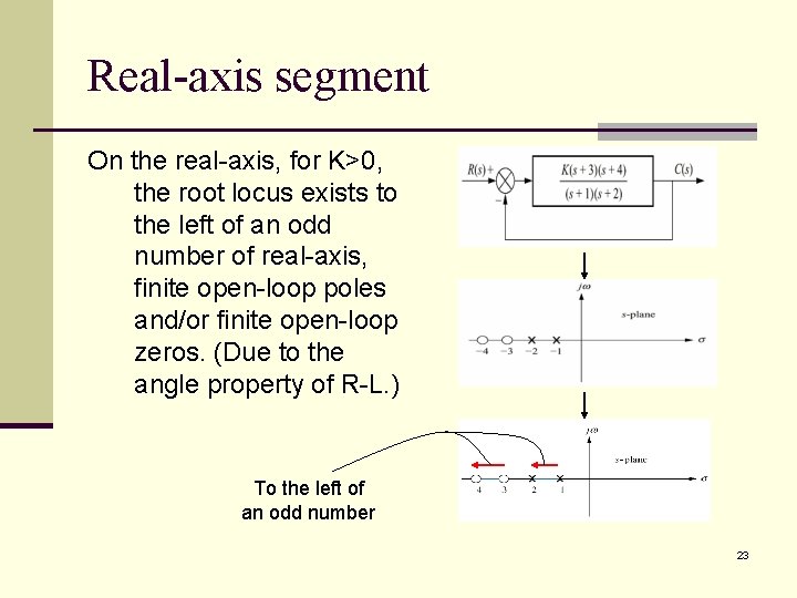
Real-axis segment On the real-axis, for K>0, the root locus exists to the left of an odd number of real-axis, finite open-loop poles and/or finite open-loop zeros. (Due to the angle property of R-L. ) To the left of an odd number 23
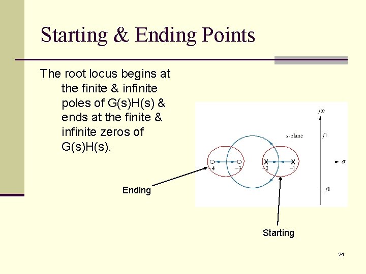
Starting & Ending Points The root locus begins at the finite & infinite poles of G(s)H(s) & ends at the finite & infinite zeros of G(s)H(s). Ending Starting 24
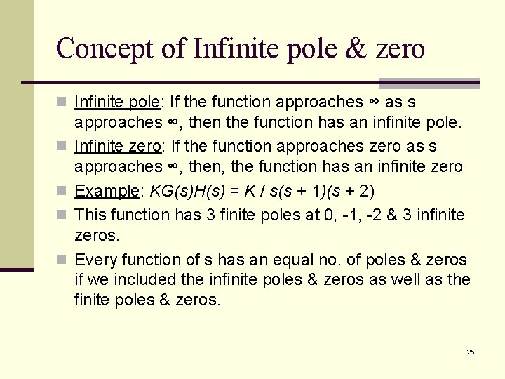
Concept of Infinite pole & zero n Infinite pole: If the function approaches ∞ as s n n approaches ∞, then the function has an infinite pole. Infinite zero: If the function approaches zero as s approaches ∞, then, the function has an infinite zero Example: KG(s)H(s) = K / s(s + 1)(s + 2) This function has 3 finite poles at 0, -1, -2 & 3 infinite zeros. Every function of s has an equal no. of poles & zeros if we included the infinite poles & zeros as well as the finite poles & zeros. 25
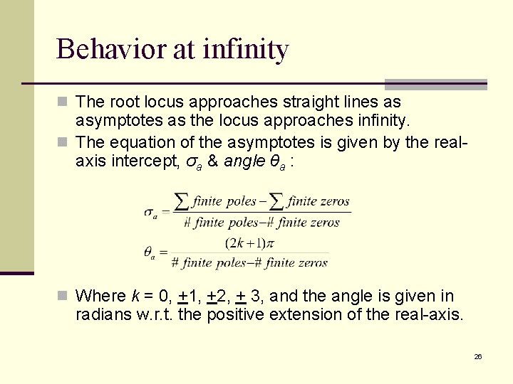
Behavior at infinity n The root locus approaches straight lines as asymptotes as the locus approaches infinity. n The equation of the asymptotes is given by the realaxis intercept, σa & angle θa : n Where k = 0, +1, +2, + 3, and the angle is given in radians w. r. t. the positive extension of the real-axis. 26
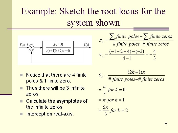
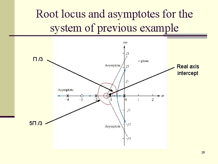
Example: Sketch the root locus for the system shown n Notice that there are 4 finite poles & 1 finite zero. n Thus there will be 3 infinite zeros. n Calculate the asymptotes of the infinite zeros: n Intercept on real-axis. 27
Root locus and asymptotes for the system of previous example Π /3 Real axis intercept 5Π /3 28
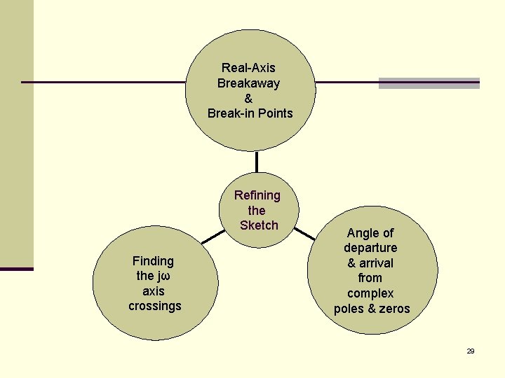
Real-Axis Breakaway & Break-in Points Refining the Sketch Finding the jω axis crossings Angle of departure & arrival from complex poles & zeros 29
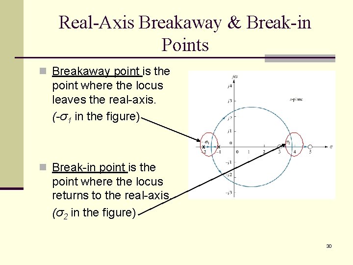
Real-Axis Breakaway & Break-in Points n Breakaway point is the point where the locus leaves the real-axis. (-σ1 in the figure) n Break-in point is the point where the locus returns to the real-axis. (σ2 in the figure) 30
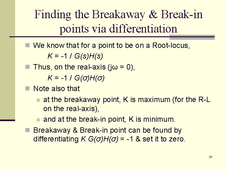
Finding the Breakaway & Break-in points via differentiation n We know that for a point to be on a Root-locus, K = -1 / G(s)H(s) n Thus, on the real-axis (jω = 0), K = -1 / G(σ)H(σ) n Note also that n at the breakaway point, K is maximum (for the R-L on the real-axis), n and at the break-in point, K is minimum. n Breakaway & Break-in point can be found by differentiating K G(σ)H(σ) = -1 & set it to zero. 31
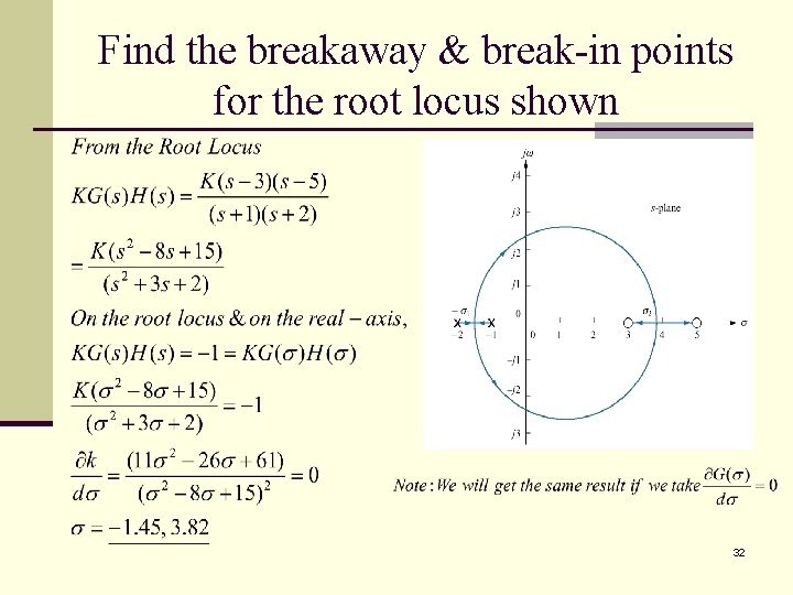
Find the breakaway & break-in points for the root locus shown 32
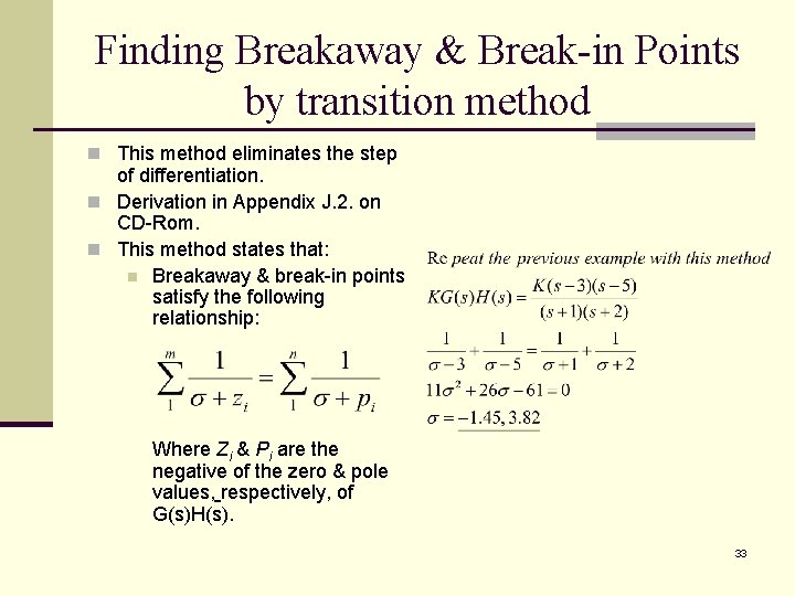
Finding Breakaway & Break-in Points by transition method n This method eliminates the step of differentiation. n Derivation in Appendix J. 2. on CD-Rom. n This method states that: n Breakaway & break-in points satisfy the following relationship: Where Zi & Pi are the negative of the zero & pole values, respectively, of G(s)H(s). 33
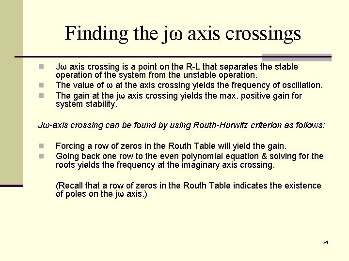
Finding the jω axis crossings n n n Jω axis crossing is a point on the R-L that separates the stable operation of the system from the unstable operation. The value of ω at the axis crossing yields the frequency of oscillation. The gain at the jω axis crossing yields the max. positive gain for system stability. Jω-axis crossing can be found by using Routh-Hurwitz criterion as follows: n n Forcing a row of zeros in the Routh Table will yield the gain. Going back one row to the even polynomial equation & solving for the roots yields the frequency at the imaginary axis crossing. (Recall that a row of zeros in the Routh Table indicates the existence of poles on the jω axis. ) 34
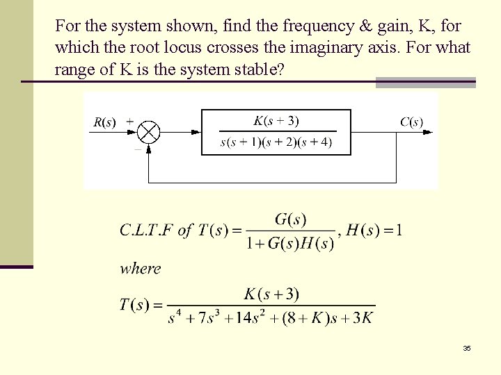
For the system shown, find the frequency & gain, K, for which the root locus crosses the imaginary axis. For what range of K is the system stable? 35
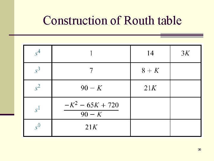
Construction of Routh table 36
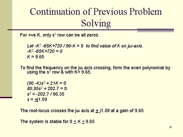
Continuation of Previous Problem Solving For +ve K, only s 1 row can be all zeros. Let -K 2 -65 K+720 / 90 -K = 0 to find value of K on jω-axis. -K 2 -65 K+720 = 0 K = 9. 65 To find the frequency on the jω axis crossing, form the even polynomial by using the s 2 row & with K= 9. 65, (90 -K)s 2 + 21 K = 0 80. 35 s 2 + 202. 7 = 0 s 2 = -202. 7 / 80. 35 s = +j 1. 59 The root-locus crosses the jω axis at + j 1. 59 at a gain of 9. 65 The system is stable for 0 < K < 9. 65 37
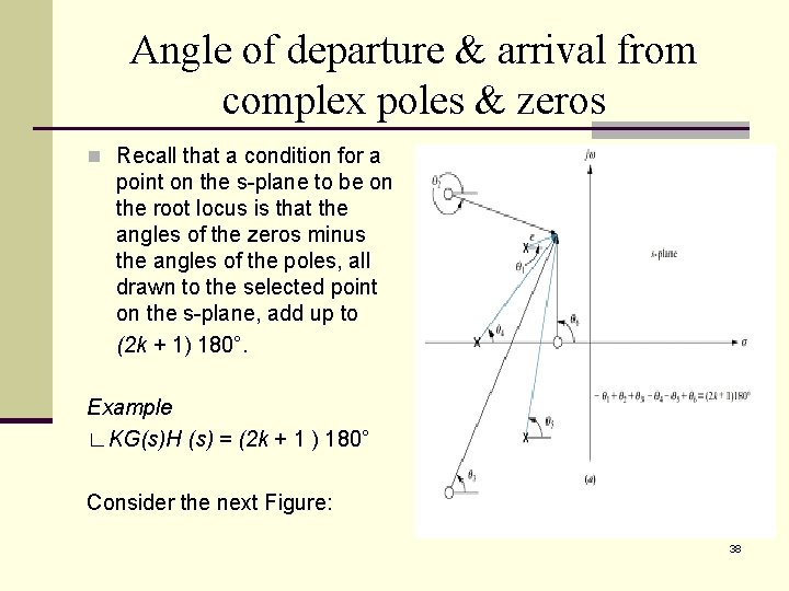
Angle of departure & arrival from complex poles & zeros n Recall that a condition for a point on the s-plane to be on the root locus is that the angles of the zeros minus the angles of the poles, all drawn to the selected point on the s-plane, add up to (2 k + 1) 180°. Example ∟KG(s)H (s) = (2 k + 1 ) 180° Consider the next Figure: 38
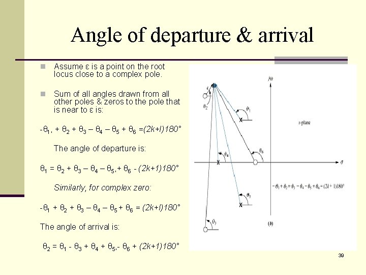
Angle of departure & arrival n Assume ε is a point on the root locus close to a complex pole. n Sum of all angles drawn from all other poles & zeros to the pole that is near to ε is: -θ 1, + θ 2 + θ 3 – θ 4 – θ 5 + θ 6 =(2 k+I)180° The angle of departure is: θ 1 = θ 2 + θ 3 – θ 4 – θ 5, + θ 6 - (2 k+1)180° Similarly, for complex zero: -θ 1 + θ 2 + θ 3 – θ 4 – θ 5 + θ 6 = (2 k+I)180° The angle of arrival is: θ 2 = θ 1 - θ 3 + θ 4 + θ 5, - θ 6 + (2 k+1)180° 39
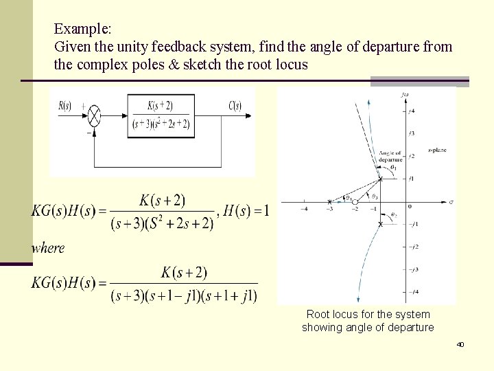
Example: Given the unity feedback system, find the angle of departure from the complex poles & sketch the root locus Root locus for the system showing angle of departure 40
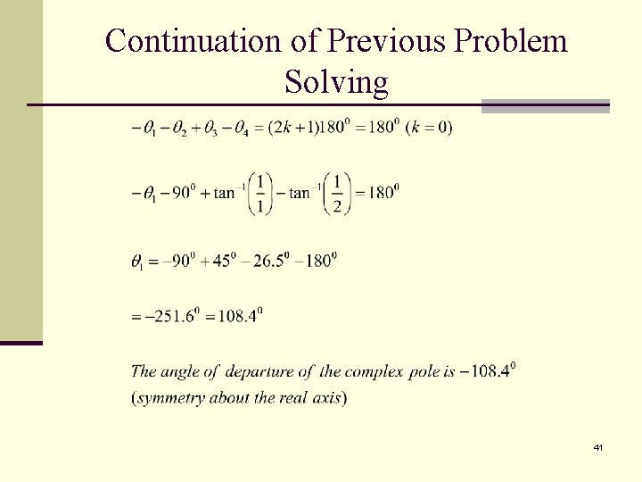
Continuation of Previous Problem Solving 41
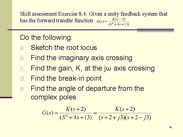
Skill assessment Exercise 8. 4: Given a unity feedback system that has the forward transfer function Do the following: a. Sketch the root locus b. Find the imaginary axis crossing c. Find the gain, K, at the jω axis crossing d. Find the break-in point e. Find the angle of departure from the complex poles 42
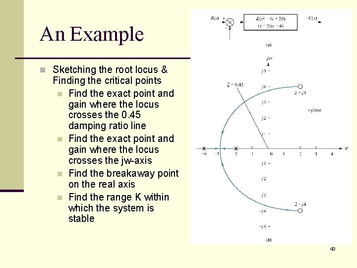
An Example n Sketching the root locus & Finding the critical points n Find the exact point and gain where the locus crosses the 0. 45 damping ratio line n Find the exact point and gain where the locus crosses the jw-axis n Find the breakaway point on the real axis n Find the range K within which the system is stable 43
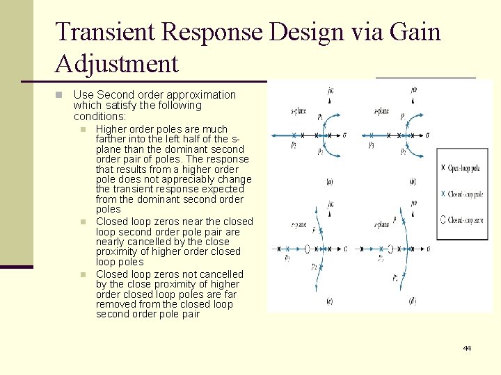
Transient Response Design via Gain Adjustment n Use Second order approximation which satisfy the following conditions: n n n Higher order poles are much farther into the left half of the splane than the dominant second order pair of poles. The response that results from a higher order pole does not appreciably change the transient response expected from the dominant second order poles Closed loop zeros near the closed loop second order pole pair are nearly cancelled by the close proximity of higher order closed loop poles Closed loop zeros not cancelled by the close proximity of higher order closed loop poles are far removed from the closed loop second order pole pair 44
Please Read!!! n Generalized Root Locus n Root Locus for Positive-Feedback Systems 45
Pole Sensitivity n Since Root Locus is a plot of the Closed Loop Poles as a system parameter is varied any change in the parameter will change the system performance too! n Root Locus exhibits nonlinear relationship between gain and pole n n Along some sections of the RL – very small changes in gain yield very large changes in pole location and hence performance High Sensitivity to changes in gain Along other sections of the RL – very large changes in gain yield very small changes in pole location Low Sensitivity to changes in gain n Preferences Low Sensitivity to changes in gain 46
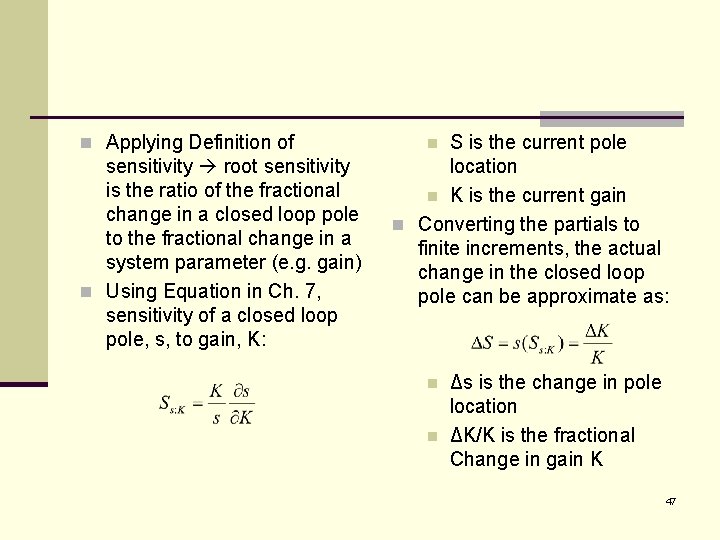
n Applying Definition of sensitivity root sensitivity is the ratio of the fractional change in a closed loop pole to the fractional change in a system parameter (e. g. gain) n Using Equation in Ch. 7, sensitivity of a closed loop pole, s, to gain, K: S is the current pole location n K is the current gain n Converting the partials to finite increments, the actual change in the closed loop pole can be approximate as: n n n Δs is the change in pole location ΔK/K is the fractional Change in gain K 47
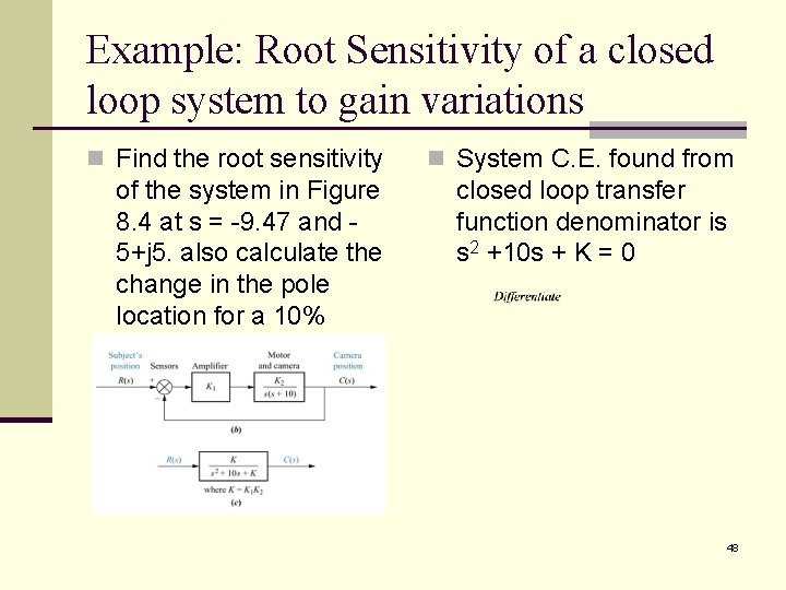
Example: Root Sensitivity of a closed loop system to gain variations n Find the root sensitivity n System C. E. found from of the system in Figure 8. 4 at s = -9. 47 and 5+j 5. also calculate the change in the pole location for a 10% change in K closed loop transfer function denominator is s 2 +10 s + K = 0 48