Power Transmission Drivetrain Creating Effective Robot Mechanisms Drivetrain

Power Transmission & Drivetrain

Creating Effective Robot Mechanisms • Drivetrain: Moves Quickly Has Good Pushing Power (Power & Traction) Turns Easily Good Control • Manipulation: Picks up, Moves or Throws Game Pieces Consistently • Motors do not Overheat, Breakers do not Trip

Power Transmission & Drivetrain Basic Drive Train Two Wheel Drive With Casters

Power Transmission & Drivetrain Basic Drive Train Two Wheel Drive All Traction Wheels

Power Transmission & Drivetrain Basic Drive Train Two Wheel Drive Omniwheels on one Axle

Power Transmission & Drivetrain Basic Drive Train Four Wheel Drive All Traction Wheels

Power Transmission & Drivetrain Basic Drive Train Four Wheel Drive Omniwheels on one Axle

Power Transmission & Drivetrain Drive Train Six Wheel Drive

Power Transmission & Drivetrain Drive Train Option: Motor mounted shaft down with bevel gear drive Four wheel Drive Super Traction Wheels All Wheels Steer Turning Mode

Power Transmission & Drivetrain Drive Train Option: Motor mounted shaft down with bevel gear drive Four wheel Drive Super Traction Wheels All Wheels Steer Side Move Mode

Power Transmission & Drivetrain Mecanum Drive Train

Power Transmission Possibilities Transfer Power to another place Reverse Direction of Input Change Motion Type Increase Speed and Distance while decreasing torque Decrease Speed and Distance while increasing torque

Power Transmission Elements Levers Class 1 Class 2 Class 3 Give me a lever long enough and a fulcrum on which to place it, and I shall move the world. Archimedes

Power Transmission Elements Levers in Action 25 Lbs out 8” Stroke 50 Lbs Applied 4” Stroke Note: connecting elements should be perpendicular at mid stroke! What class Lever?

Power Transmission Elements Levers in Action 100 Lbs out 2” Stroke 50 Lbs Applied 4” Stroke Do Levers need to be Straight? What class Lever? Note: connecting elements should be perpendicular at mid stroke!

Power Transmission Elements Chains & Belts

Power Transmission Elements Friction Drive Gear Drive

Power Transmission Elements Rotary Motion To Linear Rack & Pinion

Power Transmission Elements Rotary Motion To Linear

Power Transmission Elements Calculating Ratios of a Powertrain 2 inches D or 20 Teeth 3000 RPM 100 in/oz Input element size Output element size Input element size 6 inches D or 60 Teeth = Speed(RPM) & Distance Ratio 2 =. 33 X 3000 = 1000 RPM out 6 = Torque & Force Ratio 6 = 3 X 100 = 300 in/oz out 2

Power Transmission Elements Calculating Ratios of a Powertrain 6 inches D 2 inches D or 20 Teeth 3000 RPM 100 in/oz 1” D 4” D More than one ratio in a system? Multiply the individual ratios to find the overall ratio 2 1 X 6 4 =. 0825 Speed Ratio X 3000 RPM= 247 RPM out 6 4 X 2 1 = 12 Torque Ratio X 100 in/oz= 1200 in/oz out

Power Transmission Elements Important Terms Torque- The twisting or rotational force of a shaft (Driver or Driven) Measured as a force applied a defined distance from the center of rotation Examples: Foot pound, Inch pound, inch ounce, newton meter 1 Foot Pound Distance 12 inches Center of Rotation Force 1 pound

Power Transmission Elements Important Terms RPM’s –Revolutions per minute The Angular Velocity of an object- How fast is it turning? Note: The CIM motor used for drive power on most robots turns at a about 5000 RPMs unloaded
 ability to do work Always must include")
Power Transmission Elements Important Terms Power –(Horsepower) ability to do work Always must include a force, a distance, and time 1 horsepower= lift 550 pounds one foot in one second 1 horsepower= 746 watts Note: The Cim motor power ratings : Voltage: 12 volt DC No load RPM: 5, 310 (+/- 10%) Free Current: 2. 7 amps and 68 amps) Stall Torque: 2. 42 N-m, or 343. 4 oz-in Stall Current: 133 amps Maximum Power: 337 Watts (at 2655 rpm, 172 oz-in)

Power Transmission Elements What You Need to Know When Designing 1 -Amount of load that needs to be moved? (Force) 2 -How fast does it need to be moved ? (Time) 3 - How far does it need to go? (Distance) If this looks familiar, it is the power requirement of the task!

Power Transmission Elements Common Mistake Connecting a motor or piston to a mechanism without calculating the output force, distance and speed. This happened-more than once! A CIM motor connected directly to a 6” Diameter Wheel Speed of bot at 2655 CIM RPM --- 69 feet per second (FPS) (Most bots have a maximum velocity of 10 FPS. Faster makes for a hard to control robot) Load applied to ground at CIM 172 in/oz----2 pounds of force (To drive a 130 pound robot) Result-Bot does not move, breakers trip, magic white smoke?

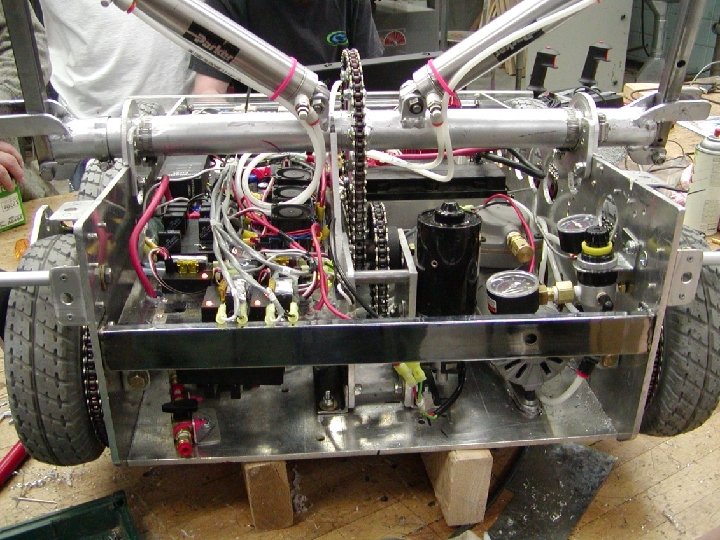
Power Transmission Elements Fisher-Price Gear Box Analysis Input R 550 motor 17, 250 RPM. 83 in/oz torque 71 19 25 62 79 38 12 19 Wheel
 R 550 motor 17,")
Power Transmission Elements Fisher-Price Gear Box Analysis Input RPM (speed) R 550 motor 17, 250 RPM. 83 in/oz torque 71 19 62 79 25 Speed Ratio 19 25 19 12 X X X =. 008 71 79 62 38 38 12 19 6” Wheel . 008 X 17, 200 RPM = 140 RPM Output X 18” Wheel C = 2537 IPM /12=211 fpm/60= 3. 5 fps

Power Transmission Elements Fisher-Price Gear Box Analysis Input Torque R 550 motor 17, 250 RPM. 83 in/oz torque 71 19 62 79 25 . 83 in/oz = 12 19 Torque Ratio 71 79 62 38 X X X = 122 19 25 19 12 122 X 38 6”D Wheel 101 in oz output torque / 3” radius of wheel = 34 oz at ground

Power Transmission Elements Identify and research your available motors Google search to find rated RPM and Torque, as well as power draw(Amps) Design your mechanisms carefully Calculate ratios and output distance, force applied, and time to actuate NOTE: Match time is two minutes! A slow mechanism will reduce your performance Always plan for adjustability. Adding extra fulcrum, input , and output attachment points is easier at the time initial manufacture Always use double shear attachments when possible. They are much stronger and greatly improve the function of the mechanism Single Shear Double Shear
- Slides: 32