Power System Protection switchgear Prepared by Mr Khairul

Power System Protection & switchgear Prepared by : Mr Khairul Anuar bin Mohd Nor

Faults, types & effects When a consumer requests electrical power from a supply authority, ideally all that is required is a cable and a transformer. A simple distribution system

This is called a radial system and can be shown schematically in the following manner A radial distribution system

Advantages • If a fault occurs at T 2 then only the protection on one leg connecting T 2 is called into operation to isolate this leg. The other consumers are not affected. Disadvantages • If the conductor to T 2 fails, then supply to this particular consumer is lost completely and cannot be restored until the conductor is replaced/repaired.

This disadvantage can be overcome by introducing additional/parallel feeders connecting each of the consumers radially. However, this requires more cabling and is not always economical. The fault current also tends to increase due to use of two cables. Radial distribution system with parallel feeders

The Ring main system, which is the most favoured, then came into being. Here each consumer has two feeders but connected in different paths to ensure continuity of power, in case of conductor failure in any section. A ring main distribution system

Advantages • Essentially, meets the requirements of two alternative feeds to give 100% continuity of supply, whilst saving in cabling/copper compared to parallel feeders. Disadvantages • For faults at T 1 fault current is fed into fault via two parallel paths effectively reducing the impedance from the source to the fault location, and hence the fault current is much higher compared to a radial path.

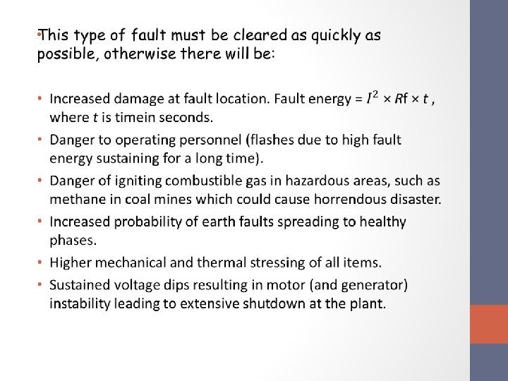
“Protection must therefore be fast and discriminate correctly, so that other consumers are not interrupted. ”

“It is not practical to design and build electrical equipment or networks to eliminate the possibility of failure in service. It is therefore an everyday fact that different types of faults occur on electrical systems, however infrequently, and at random locations. ”

Faults can be broadly classified into two main areas, which have been designated ‘active’ and ‘passive’.

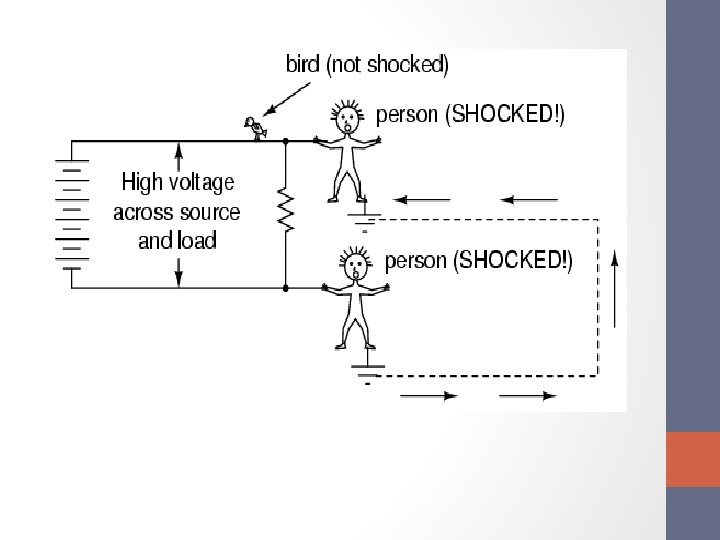
Active Faults • The ‘active’ fault is when actual current flows from one phase conductor to another (phase-tophase), or alternatively from one phase conductor to earth (phase-to-earth). • This type of fault can also be further classified into two areas, namely the ‘solid’ fault and the ‘incipient’ fault.

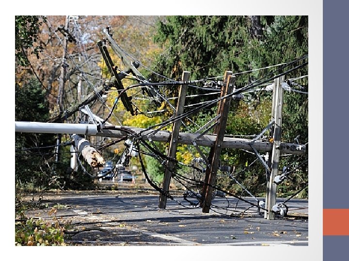
The solid fault occurs as a result of an immediate complete breakdown of insulation as would happen if, say, • • a pick struck an underground cable, bridging conductors, the cable was dug up by a bulldozer. In mining, a rockfall could crush a cable, as would a shuttle car. In these circumstances the fault current would be very high resulting in an electrical explosion.

The ‘incipient’ fault, on the other hand, is a fault that starts as a small thing and gets developed into catastrophic failure. For example § some partial discharge in a void in the insulation over an extended period can burn away adjacent insulation, eventually spreading further and developing into a ‘solid’ fault. § Other causes can typically be a high-resistance joint or contact, alternatively pollution of insulators causing tracking across their surface. Once tracking occurs, any surrounding air will ionize which then behaves like a solid conductor consequently creating a ‘solid’ fault.

Partial Discharge

Passive Faults • Passive faults are not real faults in the true sense of the word, but are rather conditions that are stressing the system beyond its design capacity, so that ultimately active faults will occur. Typical examples are:

• Overloading leading to over heating of insulation (deteriorating quality, reduced life and ultimate failure). • Overvoltage: Stressing the insulation beyond its withstand capacities. • Under frequency: Causing plant to behave incorrectly. • Power swings: Generators going out-ofstep or out-of-synchronism with each other.

“It is therefore very necessary to monitor these conditions to protect the system against these conditions. ”

Types of faults on three-phase system • Largely, the power distribution is globally a three -phase distribution especially from power sources. The types of faults that can occur on a three-phase AC system.

*In underground mining applications only

It will be noted that for a phase-to-phase fault, the currents will be high, because the fault current is only limited by the inherent (natural) series impedance of the power system up to the point of fault (Ohm’s law).

Transient and permanent faults • Transient faults are faults, which do not damage the insulation permanently and allow the circuit to be safely re-energized after a short period. • A typical example would be an insulator flashover following a lightning strike, which would be successfully cleared on opening of the circuit breaker, which could then be automatically closed.

Permanent faults, as the name implies, are the result of permanent damage to the insulation. In this case, the equipment has to be repaired and recharging must not be entertained before repair/restoration.

SELAMAT BERHUJUNG MINGGU
- Slides: 26