
Power System Protection Switchgear Mr Khairul Anuar bin

Power System Protection & Switchgear Mr Khairul Anuar bin Mohd Nor
System Protection Components Protection systems have three basic components 1. Instrument Transformer 2. Relays 3. Circuit breakers
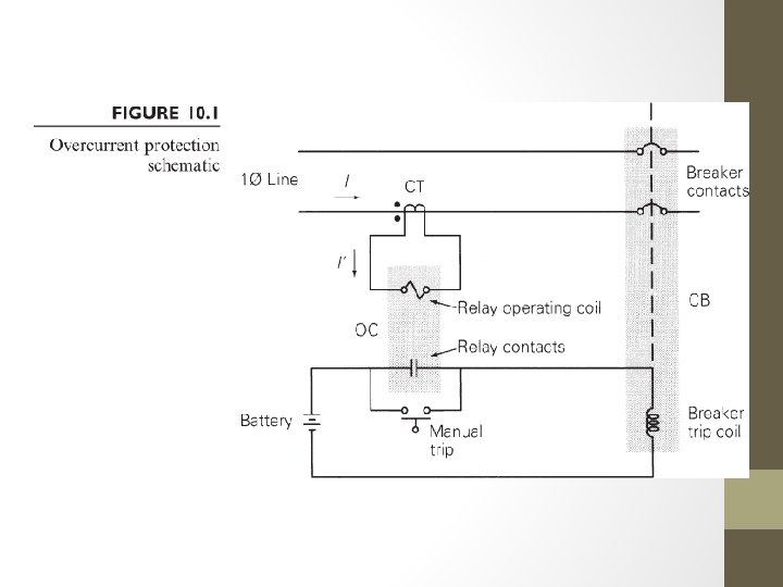
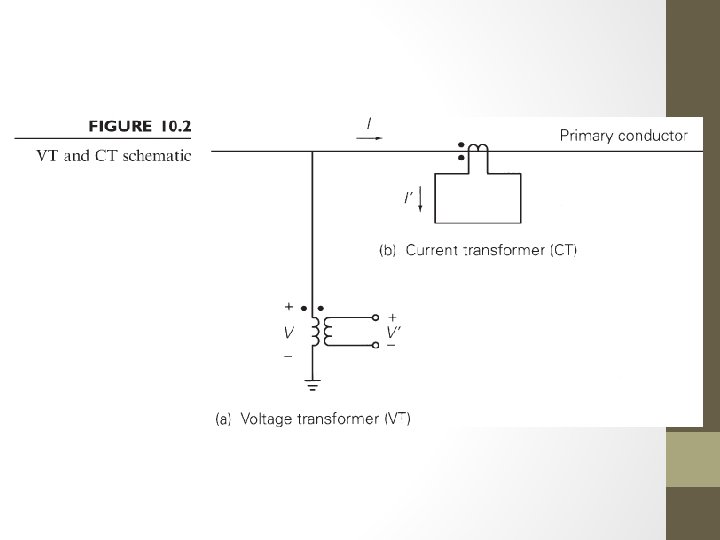
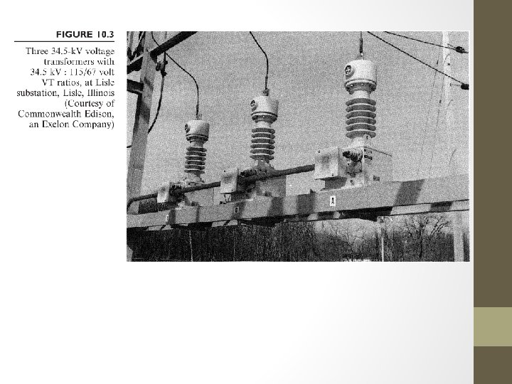
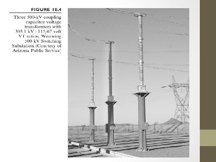
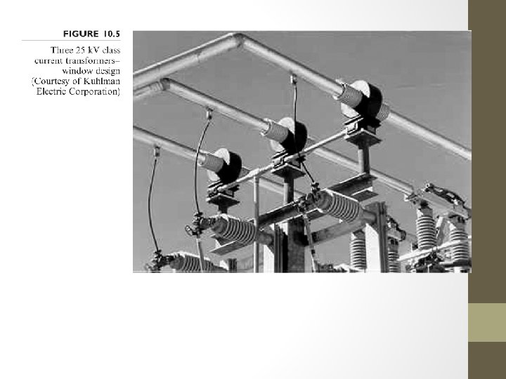
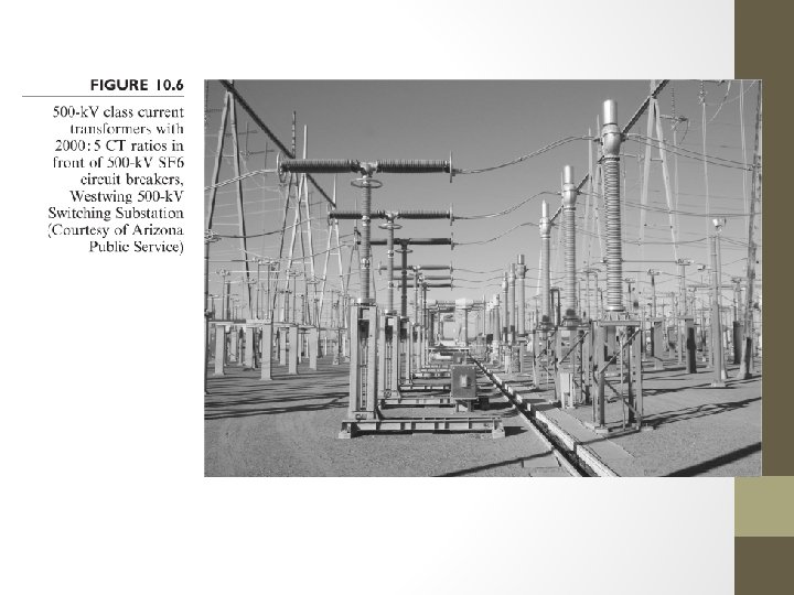
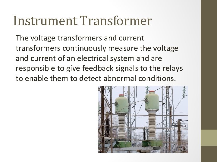
Instrument Transformer The voltage transformers and current transformers continuously measure the voltage and current of an electrical system and are responsible to give feedback signals to the relays to enable them to detect abnormal conditions.
The main tasks of instrument transformers are: • To transform currents or voltages from usually a high value to a value easy to handle for relays and instruments. • To insulate the relays, metering and instruments from the primary high-voltage system. • To provide possibilities of standardizing the relays and instruments, etc. to a few rated currents and voltages.
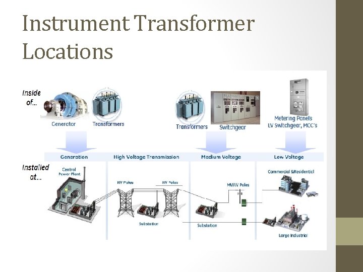
Instrument Transformer Locations
Definitions • Ref IEEE 100: • Transformer – a device that can raise or lower the ac voltage of the original source • Current Transformer – a transformer intended to have its primary winding connected in series with the conductor carrying the current to be measured or controlled • Voltage Transformer – a transformer intended to have its primary winding connected in shunt with the voltage to be measured or controlled
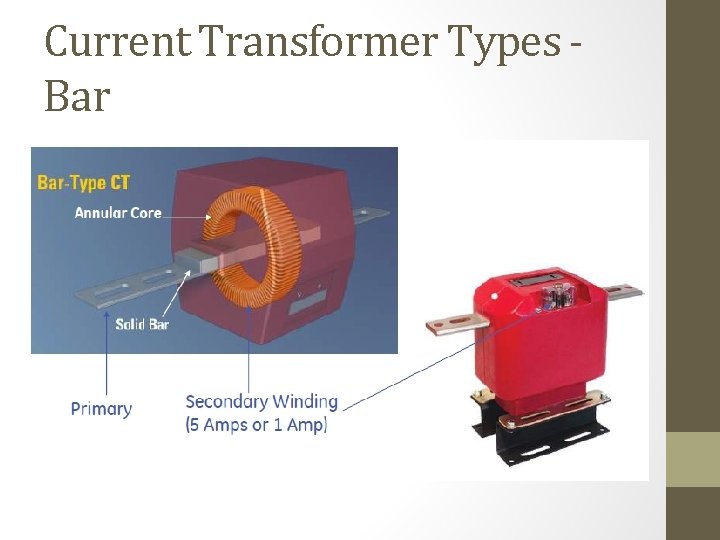
Current Transformer Types Bar
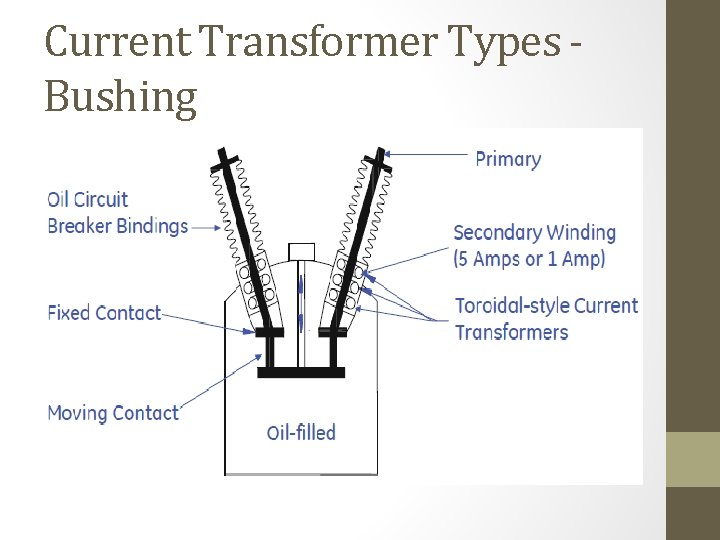
Current Transformer Types Bushing
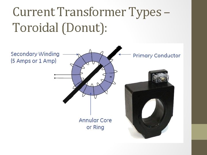
Current Transformer Types – Toroidal (Donut):
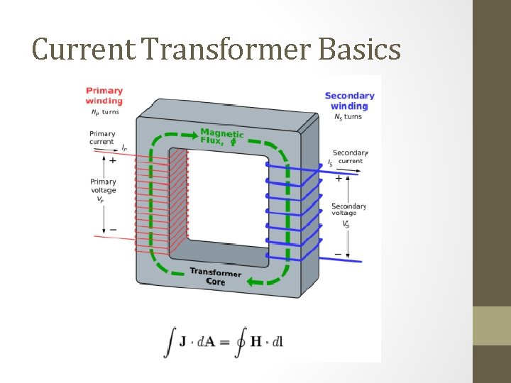
Current Transformer Basics
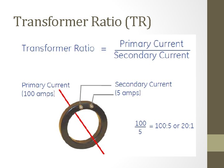
Transformer Ratio (TR)
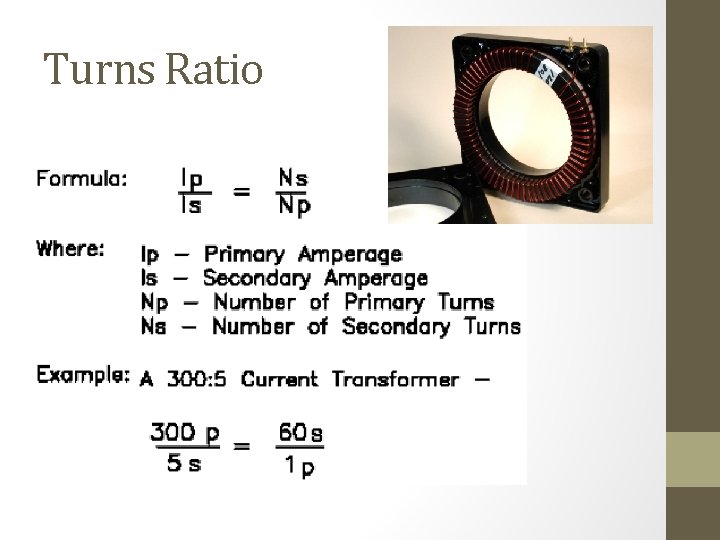
Turns Ratio

Turns Ratio Modification
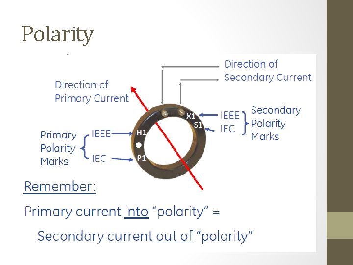
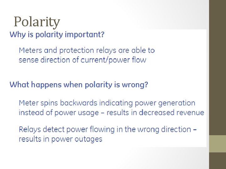
Polarity
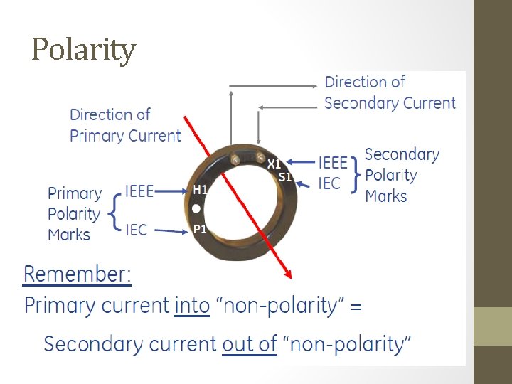
Polarity
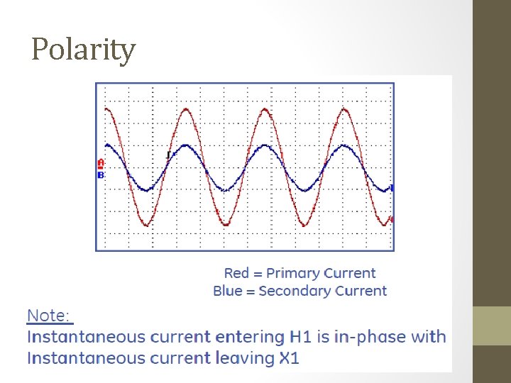
Polarity
Polarity
CT Equivalent Circuit
CT Equivalent Circuit
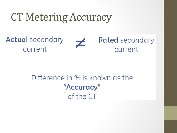
CT Metering Accuracy

IEEE CT Metering Accuracy
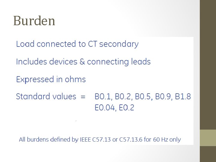
Burden
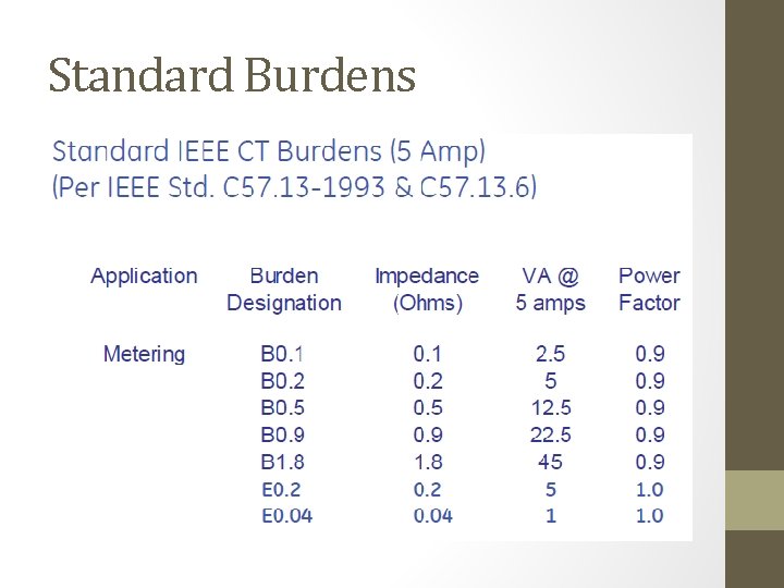
Standard Burdens
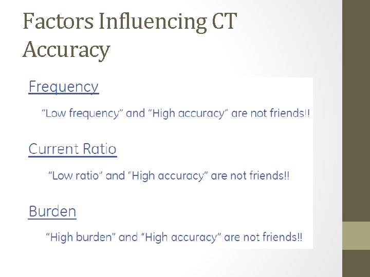
Factors Influencing CT Accuracy
CT Saturation CT saturation depends on a number of factors – Physical CT characteristics (size, rating, winding resistance, saturation voltage) – Connected CT secondary burden (wires + relays) – Primary current magnitude, DC offset (system X/R) – Residual flux in CT core
CT Saturation • Actual CT secondary currents may not behave in the same manner as the ratio (scaled primary) current during faults • End result is spurious differential current appearing in the summation of the secondary currents which may cause differential elements to operate if additional security is not applied
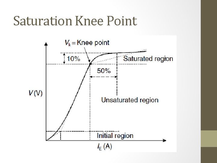
Saturation Knee Point
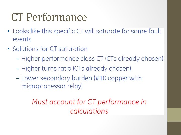
CT Performance
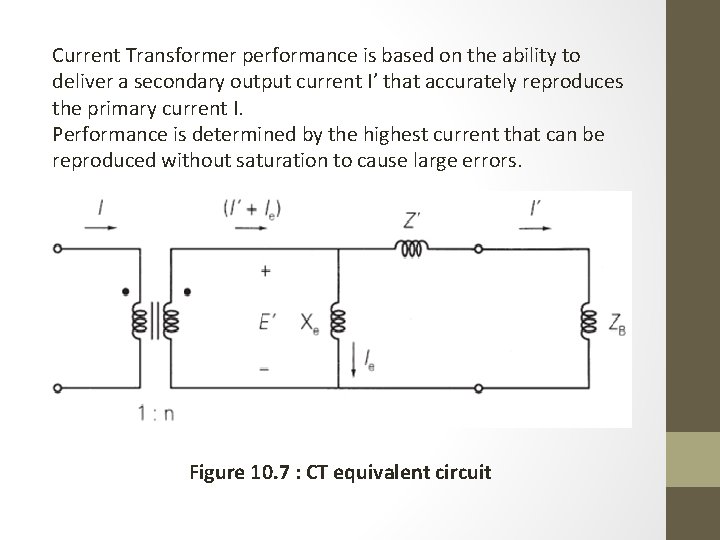
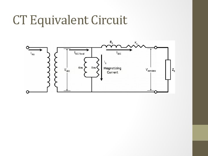
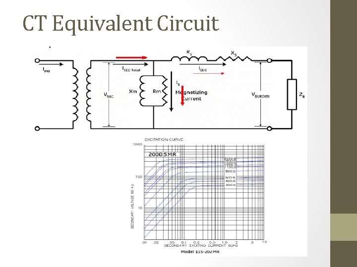
Current Transformer performance is based on the ability to deliver a secondary output current I’ that accurately reproduces the primary current I. Performance is determined by the highest current that can be reproduced without saturation to cause large errors. Figure 10. 7 : CT equivalent circuit
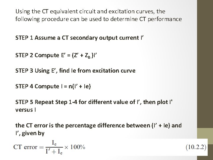
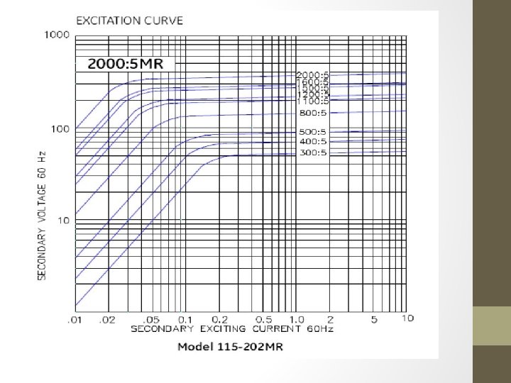
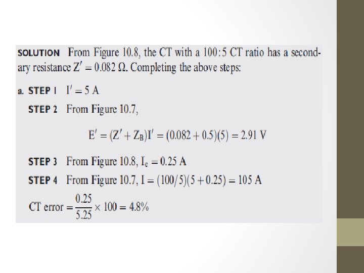
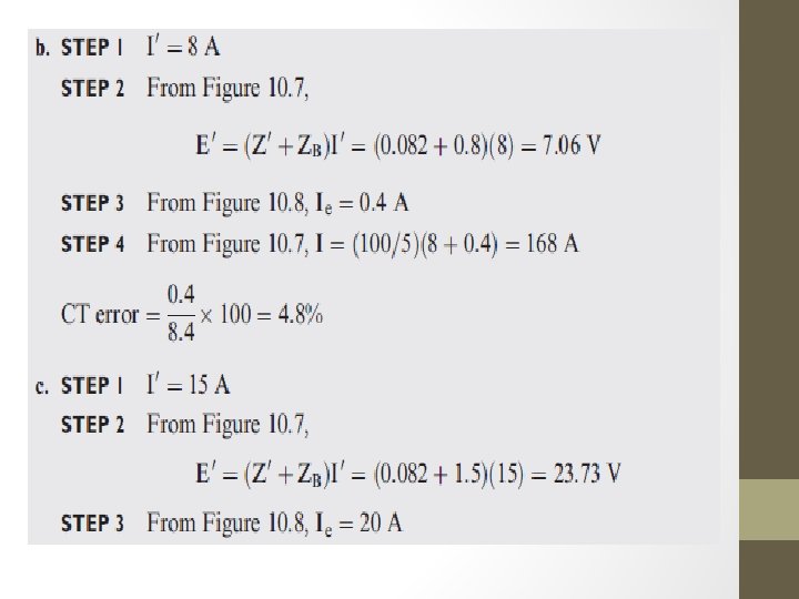
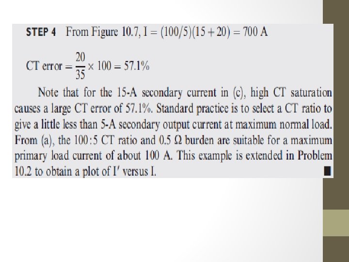
Using the CT equivalent circuit and excitation curves, the following procedure can be used to determine CT performance STEP 1 Assume a CT secondary output current I’ STEP 2 Compute E’ = (Z’ + ZB )I’ STEP 3 Using E’, find Ie from excitation curve STEP 4 Compute I = n(I’ + Ie) STEP 5 Repeat Step 1 -4 for different value of I’, then plot I' versus I the CT error is the percentage difference between (I’ + Ie) and I’, given by
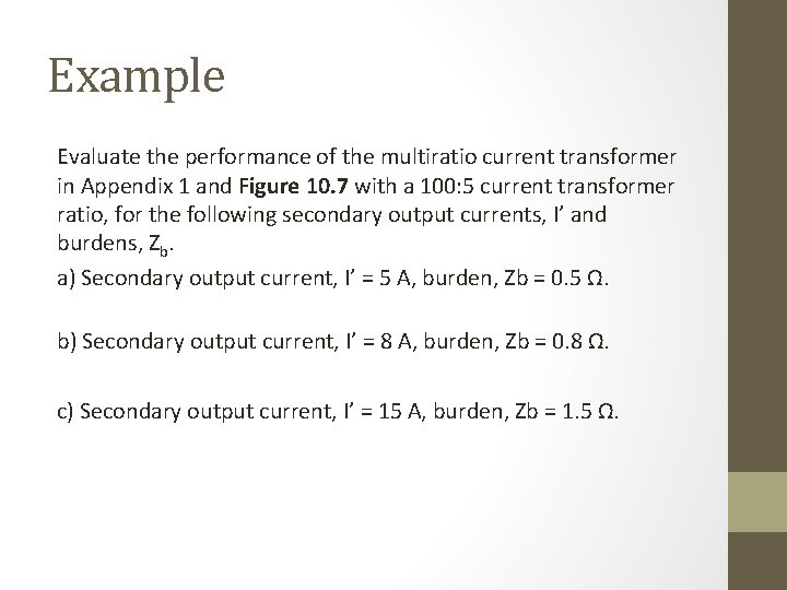
Example Evaluate the performance of the multiratio current transformer in Appendix 1 and Figure 10. 7 with a 100: 5 current transformer ratio, for the following secondary output currents, I’ and burdens, Zb. a) Secondary output current, I’ = 5 A, burden, Zb = 0. 5 Ω. b) Secondary output current, I’ = 8 A, burden, Zb = 0. 8 Ω. c) Secondary output current, I’ = 15 A, burden, Zb = 1. 5 Ω.
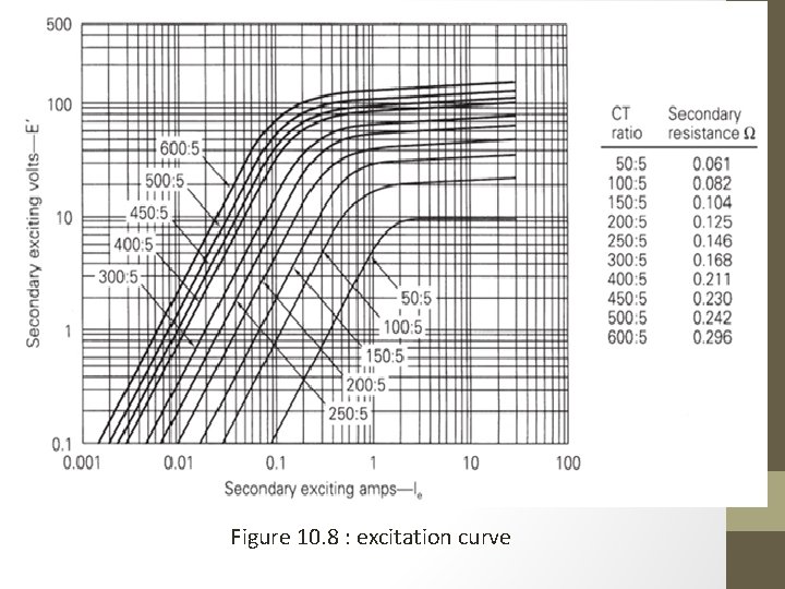
Figure 10. 8 : excitation curve
- Slides: 42