POWER SYSTEM COMMISSIONING AND MAINTENANCE PRACTICE DET 3103


 arresters are used for over-voltage protection")
 to detect")


")


 categories a) Standard")

, where Is = relay setting current TMS = Time multiplier Setting")


- Ø A timing tests is required with the PMS")

Tripping time: For Standard Inverse = time, t = At 130 % ,")

These problems led to the concept of 'Unit Protection',")


 Example: Power Transformer connection : Delta (HV) Star (LV)")


- Slides: 61
POWER SYSTEM COMMISSIONING AND MAINTENANCE PRACTICE DET 310/3 CHAPTER 10 PROTECTIVE RELAY
INTRODUCTION Ø Power systems and their components need protection from natural hazards as well as human error. Ø Lightning, wind, ice, switching surges, resonance, trees, animals and humans are some of the causes of faults. ØThese faults produce overcurrents and/or overvoltages at various locations in a power system and must be cleared before they cause before they damage any machines, transformers, lines etc. Ø This is generally accomplished by isolating the faulted portion (as small a portion as possible) of the system so that the remainder of the system can serve without interruption.
-continue: Ø In low-voltage distribution systems, lightning (surge) arresters are used for over-voltage protection and fuses and slow-acting circuit breakers are employed for over-current protection. Ø In high-voltage transmission systems reliable sensors, fast-acting relays and circuit breakers are needed to clear the fault quickly so that the stability of the remaining system is secured. Ø In short, the protection, stability and security of a power system are affected by the ability of the protection devices to detect and respond to system abnormalities like over-voltages and over-currents
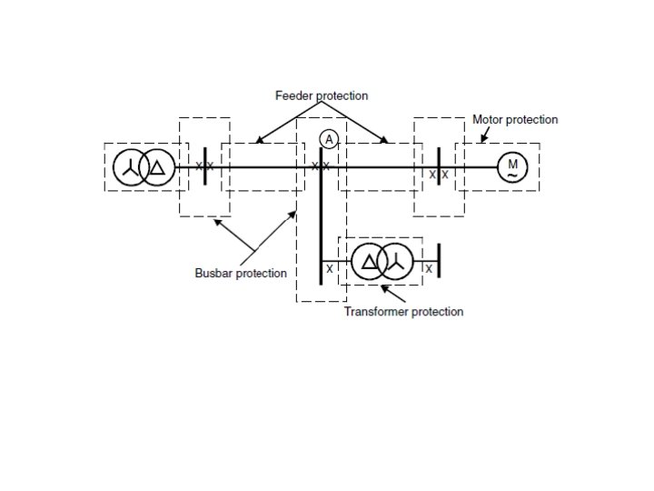
Protection Components Protection systems have three basic components: § Sensors (transducers, detectors) to detect system abnormalities § Relays (activators) to provide signals to activate the protection devices. § Circuit breakers (interrupters) to open (disconnect) the circuits.
Figure 5. 0
What is a Relay? A relay is a logical element which process the inputs (mostly voltages and currents) from the system and issues a trip decision if a fault within its jurisdiction is detected. Inputs to a relay are: - Current from a current transformer. - Voltage from a voltage transformer
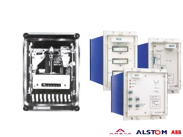
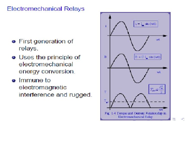
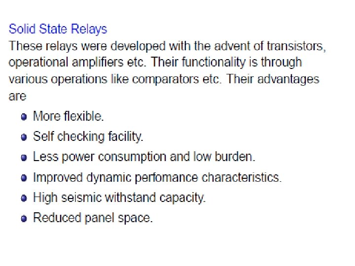
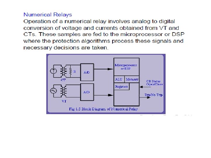
CLASSIFICATIONS OF RELAYS Relays may be classified according to the technology used: a. electromechanical b. static c. digital d. numerical
Protection Techiques The most common protection techniques can be classified into 3 categories: a) Over-current/earth fault b) Differential protection c) Distance protection
Overcurrent and earth-fault protection A protective relay which operates when the load current exceeds a preset value is called an overcurrent relay. The value of preset current above which the relay operates is known as pick up value. An overcurrent relay is used for protection of distribution lines, large motors and power equipment. An overcurrent scheme may include one or more overcurrent relays. A wide variety of time-current characteristics is available for overcurrent relays
Non-Directional Overcurrent Protection When the current in a system exceeds a predetermined value, it indicates the presence of a fault. Relaying decision is based solely on the magnitude of current. Used in radial distribution systems. Overcurrent relaying and fuse protection uses this principle.
Directional Overcurrent Protection Uses both magnitude of current and phase angle information for decision making. Used in radial distribution systems with source at both ends.
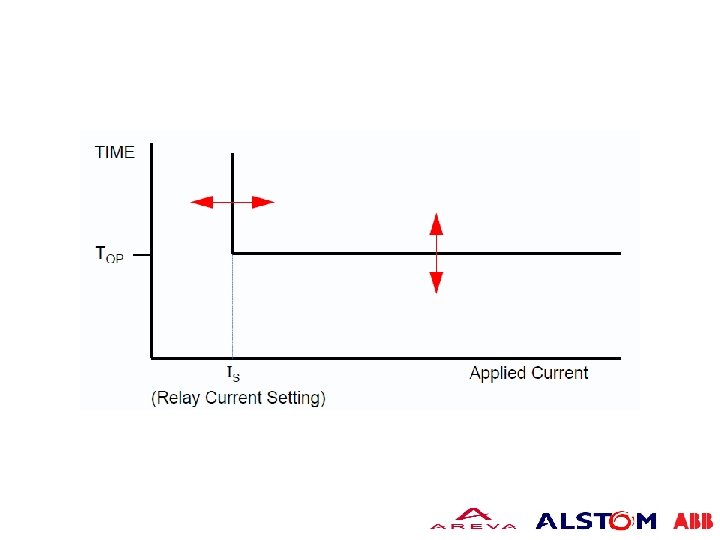
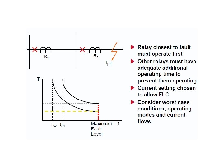
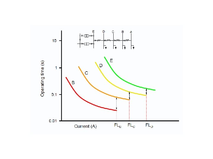
Type of Overcurrent Relay can be categorized as below: Definite time overcurrent relays §This type of relay operates after a predetermined time when the current exceeds its pick-up value. The operating time is constant, irrespective of the magnitude of the current above the pick-up value. § Operating time is independent of current § Relay closest to fault has shortest operating time. § Problem Longest operating time is at the source where fault level is highest
Instantaneous Overcurrent Relay § This type of relay operates in definite time when the current exceeds its pick up value. The operating time is constant, irrespective of the magnitude of current. § Current settings chosen so that relay closest to fault operates. § Problem relies on there being a difference in fault level between the two relay locations. § Cannot discriminate if IF 1= IF 2
IDMT overcurrent relay Generally, it can be divided into three (3) categories a) Standard Inverse (SI) b) Very Inverse-time Overcurrent (VI) c) Extremely Inverse-time Overcurrent relay (EI) Characteristics of IDMT relay Ø Current setting via plug bridge or PMS Ø Time multiplier setting via disc movement or TMS Ø Electromechanical relay only have single characteristics curve while numerical and electronics have multiple type of curve.
IDMT Electromechanical relay
Ir = (I/Is), where Is = relay setting current TMS = Time multiplier Setting TD = Time Dial setting
The tripping characteristics for different TMS settings using the SI curve
RELAY CURRENT SETTING Ø An overcurrent relay has a minimum operating current, known as the current setting of the relay. Ø The current setting must be chosen so that the relay does not operate for the maximum load current in the circuit being protected, but does operate for a current equal or greater to the minimum expected fault current.
Plug Setting Multiplier Ø It is the ratio of fault current in the relay coil to the pick – up current.
Time Multiplier Setting Ø A relay is generally provided with control to adjust the time of operation. This adjustment is known as time setting multiplier the time setting dial is calibrated from 0 to 1 in steps 0. 1. Ø These figures are multipliers to be used to convert the time derived from time/p. s. m curve into the actual operating time. Ø The actual time of operation is calculated by multiplying the time setting multiplier with the time obtained from time/ p. s. m curve of the relay.
Relay Operating Time In order to calculate the actual relay operating time, the following things must be known: (a) Time/ p. s. m curve (b) Current setting (c) Time setting (d) Fault current (e) Current transformer ratio
Example: Problem 1: – Determine the time of operation of a 5 -ampere, over current relay having a current setting of 125% and a time setting, multiplier of 0. 6 connected to supply circuit through a 400/5 current transformer when the circuit carries a fault current of 4000 A. The time of operation is 3. 5 for a P. S. M value of 8. Solution Rated secondary current of CT = 5 A Pickup current = 5 x 1. 25 = 6. 25 A Fault current in relay coil = 4000 x 5/400 = 50 A Plug-setting multiplier (P. S. M. ) = 50/6. 25 = 8
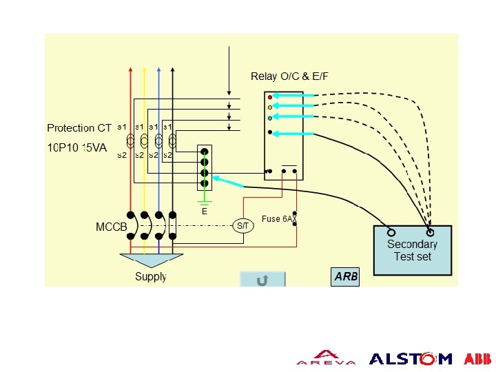
Testing and Commissioning of IDMTL Typical secondary injection commissioning tests for this type of relay consists of the following: Ø A check should be made of the minimum operating current with the plug inserted into the nominal setting (i. e 100% plug setting) and the TMS is set to 1. Ø The injected current is incrementally increased, and the disc must not creeping at current less than 100%.
Testing and Commissioning of IDMTL Ø Full travel of disc must occur, and relay flag must have dropped with an injected current less than 130% of setting. Ø The current should be then incrementally reduced to enable the disc to reset, which occur at a current less than 70% of the pick-up current
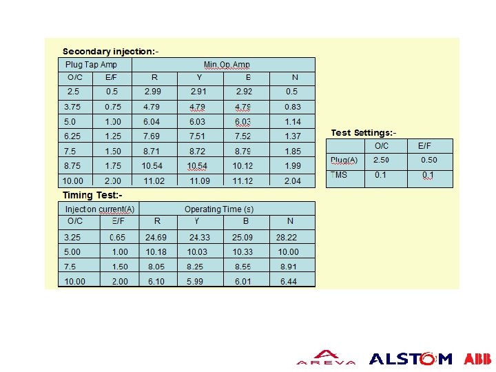
Testing and Commissioning of IDMTL(continue)- Ø A timing tests is required with the PMS at 130% setting and TMS equal to 1. This is usually carried out with a stop watch. The tests is carried out with setting of 200% and 300% of PMS. Ø The data obtained is then compared to calculation using corresponding mathematical formulation. Ø An error of 10% is usually acceptable.
Example: Determine the magnitude of fault current, secondary current and tripping time at 130%, 200% and 300% for a standard inverse relay having a parameters as shown below: PSM = 100%, CT ratio 500/5; TMS= 0. 1 Solutions: Fault current: 100% = 500 A; 130 % = 1. 3 x 500 A = 650 A 200 % = 2 x 500 A = 1000 A 300 % = 3 x 500 A = 1500 A Secondary Current: 130% = 1. 3 x 5 = 6. 5 A 200% = 2. 0 x 5 = 10 A 300 % = 3. 0 x 5 = 15 A
Example (continue)Tripping time: For Standard Inverse = time, t = At 130 % , t = At 200 %, t = At 300 %, t =
10. 4. 2 Differential Relay 10. 4. 2. 1 Introduction The graded overcurrent systems previously described though attractively simple in principle, do not meet all the protection requirements of a power system. Application difficulties are encountered for two reasons: 1) satisfactory grading cannot always be arranged for a complex network, 2) the settings may lead to maximum tripping times at points in the system that are too long to prevent excessive disturbances occurring.
10. 4. 2. 1 Introduction (continue)These problems led to the concept of 'Unit Protection', where by sections of the power system are protected individually as a complete unit without reference to other sections. One form of ‘Unit Protection’ is also known as ‘Differential Protection’, as the principle is to sense the difference in currents between the incoming and outgoing terminals of the unit being protected.
Principle of Operation Differential protection, as its name implies, compares the currents entering and leaving the protected zone and operates when the differential between these currents exceeds pre-determined magnitude. The difference between the currents may be in magnitude or in phase angle or in both. For healthy operation, magnitude and angle differences must be zero. If there is a difference and that difference exceeds some value (setting valued, the relay will operate and associated circuit breaker will trip.
During external Fault, SPILL CURRENT = I 1 – I 2 = 0
During Internal Fault: Radial line: I 2 s = 0; SPILL CURRENT = I 1 S TWO Source feeding: SPILL CURRENT = I 1 S+I 2 S
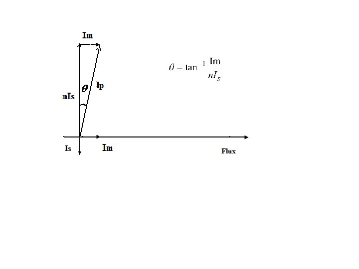
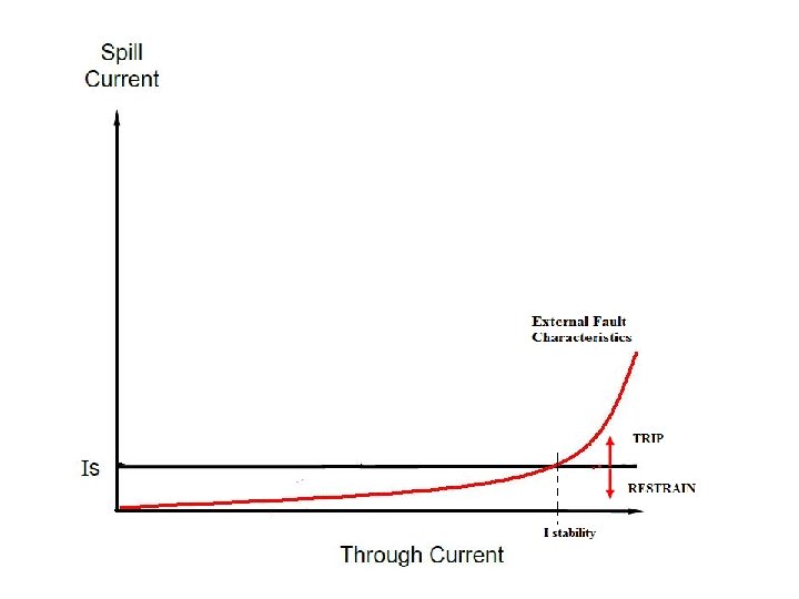
In reality, CTs will subjected to ratio and phase angle error. This will results in spill current when through fault increases.
Spill Current = Where:
BIASED/PERCENTAGE DIFFERENTIAL RELAY • Large external fault may cause false operation of simple differential relay. • To make the differential relay more stable to external faults and improve relay quality, its respectively to operation was increased by inserting restraining coils. • Two restraining (Biasing) coils and one operating are used as shown in figure below. Restraining coils will opposite the operation of operating coil. The relay will operate only when the operating force is higher than restraining force.
PERCENTAGE/BIAS DIFFERENTIAL RELAY Relay trips if operating torque is greater them restraining torque
The relay will be on verge of operation when the operating torque just balances out restraining torque, when: operating torque = restraining torque Or can be written : Where K=Nr/No Thus, the operating characteristics of the relay will be a straight line with a slope of Nr/No (K). SPILL current must be greater than a definite percentage of the through fault current for the relay to operate.
The slope of the relay is customarily expressed as a percentage. Thus a slope of 0. 4 is expressed as 40% slope
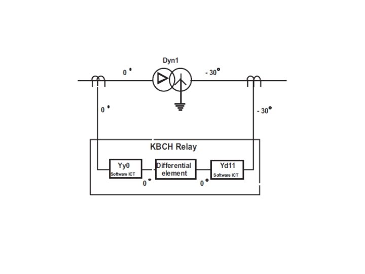
PERCENTAGE DIFFERENTIAL RELAY APPLICATION - TRANSFORMER Several consideration Ø Transformer vector group Ø the effects of the variety of earthing and winding arrangements (filtering of zero sequence currents) Ø correction for possible unbalance of signals from current transformers on either side of the windings (ratio correction) Ø the effect of magnetising inrush during initial energisation. Ø the possible occurrence of overfluxing
Current Transformer connection Transformer differential relays compare the phase and magnitude of the current entering one winding of the transformer with that leaving via the other winding(s). Any difference in phase or magnitude between the measured quantities will cause current to flow through the operate winding of the relay. If this current exceeds the relay setting, tripping of the transformer circuit breakers will be initiated. Therefore, The connection of the line CTs should compensate for any phase shift arising across the transformer. This is not for the case of modern relays as the adjustment of phase correction can be done in the relay itself.
Current Transformer connection (continue: ) Example: Power Transformer connection : Delta (HV) Star (LV) CT connection: HV secondary side = star; LV Sec side = delta Power Transformer connection: Star (HV) –Delta (LV) CT connection ; HV secondary side = delta; LV sec side = star Any magnitude difference between primary and secondary of power transformer must be balanced by corrected ratio of CTs.
Current Transformer connection
Transformer vector Group
Example:
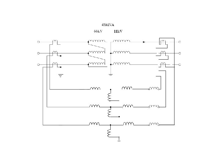
Interposing CT The main function of an interposing CT is to balance the currents supplied to the relay where there would otherwise be an imbalance due to the ratios of the main CTs. Interposing CTs are equipped with a wide range of taps that can be selected by the user to achieve the balance required. As the name suggests, an interposing CT is installed between the secondary winding of the main CT and the relay. They can be used on the primary side or secondary side of the power transformer being protected, or both. Interposing CTs also provide a convenient method of establishing a delta connection for the elimination of zero sequence currents where this is necessary.
Example: Determine the stability for 45 MVA, 66 k. V/11 k. V delta star power transformer if it is to remain stable at full load current. Relay used is 5 A type. Allow CT sizing at extra 25% margin. The bias setting is set at 40% Step 66 k. V delta 11 k. V star Full load current 125% full load CT ratios CT secondary Current 492. 05 A 500/5 393. 64/100 2952. 35 A 3000/5 2361. 88/600
Example: continue: Step Pilot wire current secondary delta 66 k. V delta CT secondary star 3. 936 A Turns ratio of interposing Interposing CT (6. 817/3. 936): 1 = 1. 731: 1 11 k. V star CT 1. 732 x 3. 926 = 6. 817 A current after 3. 936 A At 40% bias ; spill current required for tripping = 0. 4 ((3. 936 + 3. 938)/2) = 1. 57 A; Actual spill current = 3. 938 -3. 936 = 0. 002 A CT 6. 817/1. 731 = 3. 938 A