Power Plant Technology Steam and Gas Cycle Power
 by Mohamad Firdaus")

 1698")

, Nuclear, Waste heat, Renewable")

 OR FISSILE (URANIUM,")
 OR FISSILE (URANIUM,")
.")


 BOILER: TURBINE: CONDENSER: PUMP:")

 is usually very small as compared to the turbine work")


")


 • An increase in the superheat")
 • Tm 1 can also be")
")
 With temperature and pressure limitation, Tm")


 1. The most common cycle improvement employed. 2.")
 1. Although resulting extra pump and less power")


- Slides: 37
Power Plant Technology Steam and Gas Cycle Power Plant (Lecture 1) by Mohamad Firdaus Basrawi, Dr. (Eng) Mechanical Engineering Faculty mfirdausb@ump. edu. my
WHAT IS POWER PLANT? an industrial facility for the generation of electric power https: //pixabay. com/en/power-plant-ruskin-fl-florida-815799/ Fuel Prime Mover (Engine) Electricity
Industrial Revolution Period HISTORY OF POWER PLANT BC Heat-Fire (earth, water, air, fire) 1698 Savery Engine 1712 T. Newcomen Atmospheric Engine 1760 Thermal element False concept of heat 1769 James Watt Steam Engine 1798 G. V. Ramford True concept of heat http: //technology. niagarac. on. ca/staff/mcsele/newcom n. htm 1842 J. R. Mayer Heat-Work-Energy relation 1847 J. D. Joule Quantitative relation between heat and work 1878 1 st Power Plant for lighting a castle built by Sigmund Schucker in Germany (Arc Lamp) 1879 Thomas Alva Edison invented practical incandescent lamp 1882 1 st public Power Plant, Edison Electric Light Station in NY for shops and other bussiness (incandescent lamp) http: //www. tnb. com. my/about-tnb/history. html http: //en. wikipedia. org/wiki/Power_station http: //americanhistory. si. edu/powering/past/h 1 main. htm
HISTORY OF POWER PLANT IN MALAYSIA 1900 First Hydro Power Plant in Malaysia built by Raub Australian Gold Mining Company Initially 220 k. W, but now 1 MW and is connected to grid 1946 Until this year many small scale power plants was already running with a variety of fuel (coal, wood, charcoal, oil, etc. ) Central Electricity Board was established with development of a national grid project. 1965 CEB was renamed as NEB (Malay Federation) 1990 NEB was privatized with establishment of TNB. http: //www. tnb. com. my/about-tnb/history. html http: //wzwh. blogspot. com/2013/07/sungai-sempam-hydropower-plant-of-today. html
CLASSIFICATION OF POWER PLANT By fuel: Fossil-fuel (Coal, natural gas), Nuclear, Waste heat, Renewable (Geothermal, Biomass, Solar) By Prime Mover: Steam Turbine (most used), Gas turbine (peaker), Combined Cycle (Better efficiency), Reciprocating Engine (small scale), Microturbines-stirling-reciprocating engine (small scale+biogas) By Duty: Base load (constant operation, efficient and longer time for start and stop), Peaking load (Run a few hour, rapid start up and stop, gas turbine-reciprocating engine-hydro), Load Following (small scale) 5
ROAD MAP OF POWER PLANT SOFC+GT+ST IGFC GT+ST IGCC History of Thermal Power Plant Efficiency http: //www. jsme-fed. org/newsletters-e/2013_4/no 4. html
STEAM POWER PLANT CONVERTS THE ENERGY IN FOSSILS (COAL, OIL, GAS) OR FISSILE (URANIUM, THORIUM) INTO SHAFT AND ULTIMITELY INTO ELECTRICITY. https: //en. wikipedia. org/wiki/Fossil_fuel_power_station The efficiency of the vapor power cycle would thus be:
STEAM POWER PLANT CONVERTS THE ENERGY IN FOSSILS (COAL, OIL, GAS) OR FISSILE (URANIUM, THORIUM) INTO SHAFT AND ULTIMITELY INTO ELECTRICITY. The efficiency of the vapor power cycle would thus be:
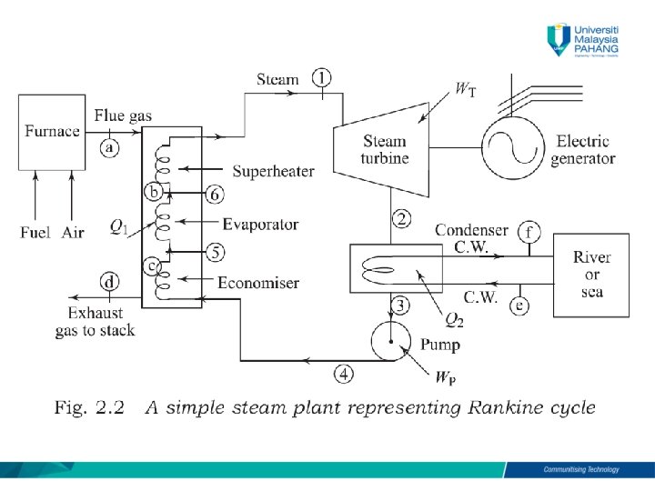
Ideal Rankine Cycle STEAM GENERATOR: A reversible constant pressure heating process (water to steam). TURBINE: A reversible adiabatic expansion of steam CONDENSER: A reversible constant pressure heat rejection process (steam to saturated liquid). PUMP: The reversible adiabatic compression. (liquid return to the initial pressure).
Ideal Rankine Cycle 1 -2 -3 -4 -B-1 is a saturated Rankine Cycle means saturated vapour enters the turbine. Cycle 1’-2’-3 -4 -B-1’ is a superheat Rankine Cycle, means superheated vapour enters the turbine.
TITLE #X 3. Rankine cycle on p-v, T-s, and h-s coordinates (a, b and c)
STEADY FLOW ENERGY EQUATION (SFEE) BOILER: TURBINE: CONDENSER: PUMP:
THE EFFICIENCY OF THE RANKINE CYCLE For reversible adiabatic compression: Since
The pump work (Wp) is usually very small as compared to the turbine work (WT), and therefore it is often neglected. Steam plant capacity is often expressed as steam rate or specific steam consumption (SSC). It is defined as rate of steam flow (kg/s) needed to generate unit shaft output (1 k. W). So, Steam rate (S. R. ) ( 9 ) The efficiency is sometimes expressed as heat rate Heat rate (H. R. ) ( 10 )
ECONOMIZER, EVAPORATOR AND SUPERHEATER Heat transfer in a steam generator has three different regimes ( 11 )
TAKE A BREAK How power plant is important in our life? Life without electricity? V 1 b
CARNOT CYCLE AND ITS LIMITATION Carnot cycle is an ideal (△T=0 and △Q=0, reversible) cycle that produce maximum possible efficiency on selected maximum- temperature. However, in real practice it cannot be achieved because the irreversibilities (friction, expansion, mixing of two fluids, heat transfer, resistance, chemical reaction, etc). Process 1 -2 -3 -4 • 3 -4 requires a large compressor to be run at very wet steam. Problem with blade erosion and cavitations will be occurred. Process 1 -2 -5 -6 -1 • 5 -6 involves with very high pressure for pump work. • 6 -4 is impossible because usually heat cannot be supplied at infinite pressure and constant temperature.
MEAN TEMPERATURE OF HEAT ADDITION Heat added reversibly at a constant pressure at 5 -6 and Tm 1 is called mean temperature of heat addition. So, the total area under 5 -6 is equal to the area under 4 -1. Then, heat added is: Since heat rejected Q 2 = h 2 -h 3=T 2(s 1 -s 4)
Cycle efficiency increases when the mean temperature of heat addition increases
HOW TO INCREASE MEAN TEMPERATURE (EFFECT OF SUPERHEAT) • An increase in the superheat increases Tm 1 and hence the cycle efficiency increase. • When superheat temperature increases, the expansion line of steam in the turbine moves to the right (1 -2 to 1’-2’). The steam quality improves and performance of the turbine also improves. • However, there is limit in the maximum temperature due to metallurgical considerations
HOW TO INCREASE MEAN TEMPERATURE (EFFECT OF SUPERHEAT) • Tm 1 can also be increased by increasing pressure because Tm 1 between state 7 -5 is greater than state 4 -1. • But, when the turbine inlet pressure increases from P 1 to P 2, and the expansion line also moves to the left side. • Since it has lower vapor quality, the moisture content at the turbine exhaust increases (x 6 < x 2). • This resultings vapour with high moisture high velocity strike turbine blades and erodes the blade. Therefore, lifetime of the blade decreases
HOW TO INCREASE MEAN TEMPERATURE (EFFECT OF SUPERHEAT)
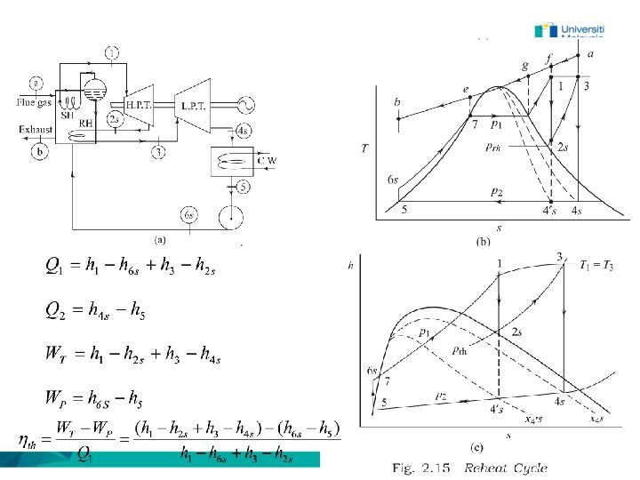
HOW TO INCREASE MEAN TEMPERATURE (EFFECT OF SUPERHEAT) With temperature and pressure limitation, Tm 1 can be increased by reheating.
• Temperature limit due to metallurgical reason is considered. • Pressure is increased but vapor is partially expensed at the HP turbine to avoid moisture. • Lower pressure vapor is reheated and fully expensed at the LP turbine • Thus, higher Tm 1, more work and higher efficiency can be obtained.
• The cycle efficiency in a single reheat plant is influenced by the pressure (Prh) at which steam is reheated. Temperature and quality must also be considered. • The optimum pressure for reheat for most of the modern power plants is 0. 25.
1. 2. 3. 4. REGENERATION Reuse heat at a condenser that is usually released to environment to preheat water at boiler. Although resulting extra pump and less power output, fuel used also can be reduced. As the whole result, efficiency increases. Although condenser size can be decreased, boiler size must be increased. This is because steam circulate must be increased to obtain same power. http: //www. ohio. edu/mechanical/thermo/Applied/Chapt. 7_11/Chapter 8 b. html
Regeneration Cycle in Malaysia (JIMAH, PD) 1. The most common cycle improvement employed. 2. Overall efficiency of 37%. 3. Shell-Tube HE
Regeneration (Two open feed water heaters) 1. Although resulting extra pump and less power output, fuel used also can be reduced. 2. As the whole result, efficiency increases.
FEEDWATER HEATERS OPEN HEATERS 1. The extracted steam mixes with feedwater and both fluid leave at common temperature. 2. The advantages: lower cost, simplicity, and high heat transfer. 3. The disadvantage: more pumps. CLOSED HEATERS 1. Extracted steam and feedwater are kept separately. 2. Closed heaters are shell-and-tube heat exchangers. 3. The advantages: no extra pump. 4. The disadvantage: complex, higher cost, lower heat transfer capacity. http: //www. ohio. edu/mechanical/thermo/Applied/Chapt. 7_11/Chapter 8 b. html
OPEN FEEDWATER HEATERS y 1 -y l l l Mixing chamber: steam extracted from the turbine mixes with the feedwater from the pump. The mixture leaves the heater (3) as saturated liquid at the heater pressure. Heat of y at OFWH (6 -3) at constant pressure increases feedwater
TWO OPEN FEEDWATER HEATERS: DIAGRAM l l Steam extract for each pressure stage (m 1, m 2). A pump is needed for each stage to flow pressure fluid to higher pressure heater.
TWO OPEN FEEDWATER HEATERS: EFFICIENCY
TWO OPEN FEEDWATER HEATERS: ENERGY BALANCE FWH 1 FWH 2
TWO CLOSED FEEDWATER HEATERS: DIAGRAM 10 7 m 1+m 2 12 l l Steam is extracted for each pressure stage (m 1, m 2). After condenser, pressure of (1 -m 2) was increased to the highest pressure. After heat exchange at HP FWH, vapour in m 1 is trapped and then it mixes with m 2 at LP FWH. Next, vapor in m 1 & m 2 are trapped and finally pumped to the highest pressure.
TWO CLOSED FEEDWATER HEATERS: FWH 1 ENERGY BALANCE 10 FWH 2 12 7