Power Flow in a Meshed System An adjustable

Power Flow in a Meshed System

• An adjustable series capacitor controls the power flow • Mechanically switched series capacitor is limited by wear and tear. • A series capacitor in a line may lead to subsynchronous resonance. • This occurs when mechanical resonance frequencies of the shaft of a multiple turbine generator unit coincides with 50 Hz minus the electrical frequency of the line.

If series capacitor is Thyristor controlled • It can be varied as often as required • Rapidly damp any sub-synchronous resonance conditions • Damp low frequency oscillations in the power flow • Avoid risk of damage to generator shaft and system collapse • Greatly enhance stability of the network.

Opportunities for FACTS q To damp oscillations at various frequencies below rated frequency. q. Enable a line to carry power closer to its thermal rating. q Mechanical switching replaced with power electronics

Relative Importance of controllable Parameters • Control of the line impedance X with a thyristor-controlled series capacitor can provide a powerful means of current control. • When the angle is not large, control of X or the angle substantially provides the control of active power. • Control of angle with phase angle regulator, which in turn control the driving voltage, provides a powerful means of controlling the current flow and hence active power flow when the angle is not large. • Injecting a voltage in series with the line and perpendicular to the current flow can increase or decrease the magnitude of current flow. • Injecting voltage in series with the line and with any phase angle with respect to the driving voltage can control the magnitude and the phase of the line current. • When the angle is not large, controlling the magnitude of one or the other line voltages can be a very cost-effective means for the control of reactive power flow through the interconnection. • Combination of the line impedance control with a series controller and voltage regulation with a shunt controller can also provide a cost-effective means to control both the active and reactive power flow between the two systems.

General symbol for FACTS controller

Series Controller could be variable impedance or variable source. All series controllers inject voltage in series with the line. Variable impedance multiplied by the current flow through it, represents an injected series voltage in the line. As long as the voltage is in phase quadrature with the line current, the series controller only supplies or consumes variable reactive power. Any other phase relationship will involve handling of real power as well. Ex: SSSC, TCSR, TSSC, TCSC.

Shunt Controller could be variable impedance, variable source or a combination of these. Shunt controllers inject current into the system at the point of connection. Variable shunt impedance connected to the line voltage causes a variable current flow and hence represents injection of current into the line. As long as the injected current is in phase quadrature with the line voltage, the shunt controller only supplies or consumes variable reactive power. Any other phase relationship will involve handling of real power as well. Examples of the shunt controllers include TCR, STATCOM, TSR, TCBR and TSC.

Combined Series - Series Controller This could be a combination of separate series controllers, which are controlled in a coordinated manner, in multilane transmission system. Or it could be a unified controller in which series controllers provide independent series reactive compensation for each line but also transfer real power among the lines via the power link. The term unified means that the dc terminals of all controller converters are connected together for real power transfer.

Example of this controller is IPFC that balances the real and reactive power flow in the lines in order to maximize the power transmission.

Combined Series-Shunt Controller This could be combination of separate shunt and series controllers, which are controlled in a coordinated manner, a Unified Power Flow Controller with series and shunt elements. Combined shunt and series controllers inject current into the system with the shunt part of the controller and voltage in series in the line with the series part of the controller.

Examples of these controllers include TCPST, UPFC and TCPAR.
 –Controls voltage •")
CONTROLLERS FOR ENHANCING POWER SYSTEM CONTROL • Static synchronous Compensator (STATCOM) –Controls voltage • Static VAR Compensator (SVC) -Controls voltage • Unified Power Flow Controller (UPFC) • Convertible Series Compensator (CSC) • Inter-line Power Flow Controller (IPFC) • Static Synchronous Series Controller (SSSC) Each of the above mentioned (and similar) controllers impact voltage, impedance, and/or angle (and power) Thyristor Controlled Series Compensator (TCSC) –Controls impedance Thyristor Controlled Phase Shifting Transformer (TCPST) - Controls angle Super Conducting Magnetic Energy Storage (SMES) -Controls voltage and power

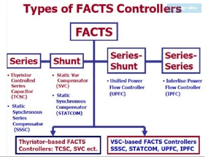
Depending on the power electronic devices used in the control, the FACTS controllers can be classified as (A) Thyristor based FACTS controller (or) Variable impedance type (B) Voltage Source Converter (VSC) -based.
 Static Var Compensator (SVC) (shunt connected) (ii)")
The variable impedance type controllers include: (i) Static Var Compensator (SVC) (shunt connected) (ii) Thyristor Controlled Series Capacitor or compensator (TCSC) (series connected) (iii) Thyristor Controlled Phase Shifting Transformer (TCPST) The VSC based FACTS controllers are: (i) Static synchronous Compensator (STATCOM) (shunt connected) (ii) Static Synchronous Series Compensator (SSSC) (series connected) (iii) Interline Power Flow Controller (IPFC) (combined series-series) (iv) Unified Power Flow Controller (UPFC) (combined shunt-series) Some of the special purpose FACTS controllers are (a) Thyristor Controller Braking Resistor (TCBR) (b) Thyristor Controlled Voltage Limiter (TCVL) (c) Thyristor Controlled Voltage Regulator (TCVR) (d) Interphase Power Controller (IPC)

The FACTS controllers based on VSC have several advantages over the variable impedance type. For example, • a STATCOM is much more compact than a SVC for similar rating and is technically superior. • It can supply required reactive current even at low values of the bus voltage and can be designed to have in built short term overload capability. • Also, a STATCOM can supply active power if it has an energy source or large energy storage at its DC terminals.

The only drawback with VSC based controllers is the requirement of using self commutating power semiconductor devices such as Gate Turn-off (GTO) thyristors, Insulated Gate Bipolar Transistors (IGBT), Integrated Gate Commutated Thyristors (IGCT). Thyristors do not have this capability and cannot be used although they are available in higher voltage ratings and tend to be cheaper with reduced losses. However, the technical advantages with VSC based controllers coupled with emerging power semiconductor devices using silicon carbide technology are expected to lead to the wide spread use of VSC based controllers in future.

Voltage Source Converter Based Controllers - An Introduction Shunt connected STATCOM Series connected SSSC Unified Power flow controller
 ensures that the")
A three phase, six pulse VSC The Phase Lock Loop (PLL) ensures that the sinusoidal component of the injected voltage is synchronized (matching in frequency and required phase angle) with the voltage of the AC bus to which VSC is connected through an inductor.
 Current Source Converter In current source converter,")
Basic Concept of Current Source Converters (CSC) Current Source Converter In current source converter, dc current flows only in one direction and the power reversal takes place by reversal of dc voltage. It differs from voltage source converter in which dc voltage has only one polarity and power reversal take place by reversal of dc current. A current source converter is as shown in fig. 1. It may be based on diodes conventional thyristors or the turn-off devices.

Diode Converter: Line Commutated Converter:

Self Commutated Converter: Fig. shows a self-commutated converter which is based on turn-off devices such as GTOs, IGBTs etc. In this converter commutation of current from the valve to valve takes place with the turn off action of the device. This converter can control power in either direction and also supply or consume reactive power as well.

A capacitor to provide stiff D. C. Voltage
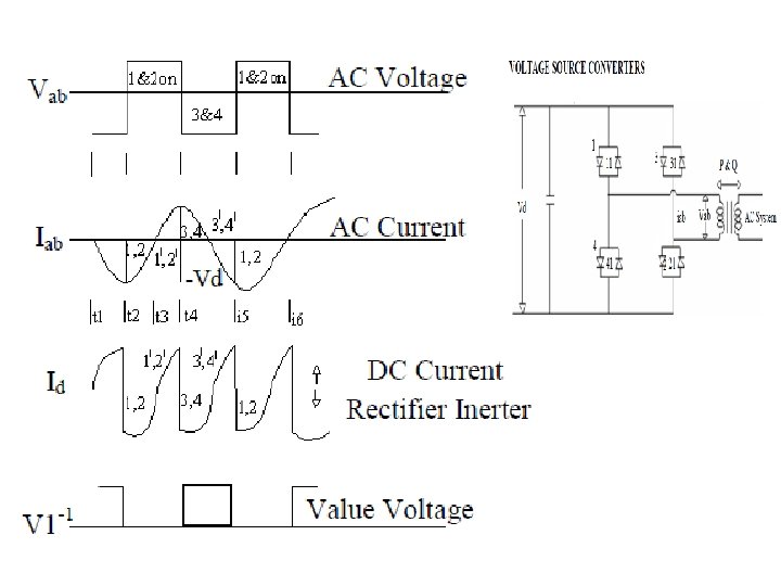
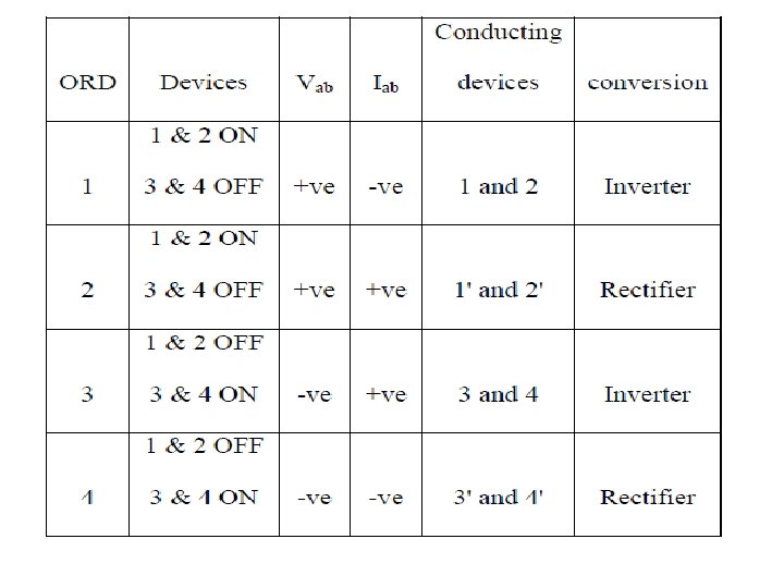

Three Phase Full Wave Bridge Converters

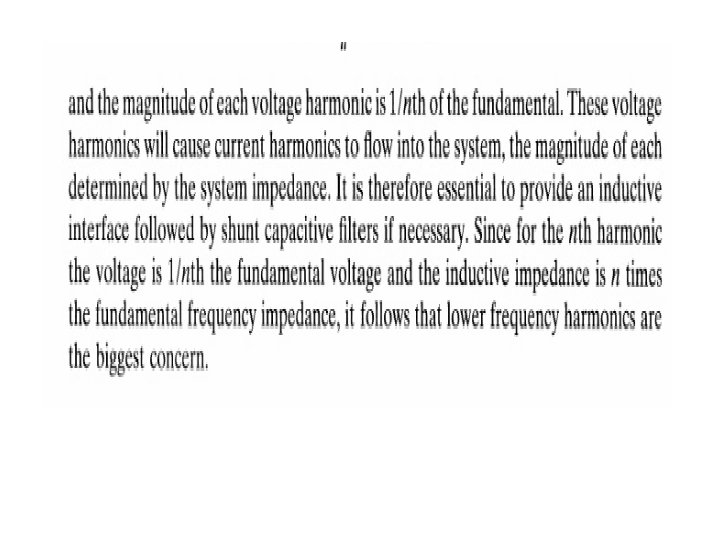
SQUARE WAVEVOLTAGE HARMONICS FOR A SINGLE PHASE BRIDGE Which includes the fundamental and the harmonics. The fundamental and individual harmonics are given by

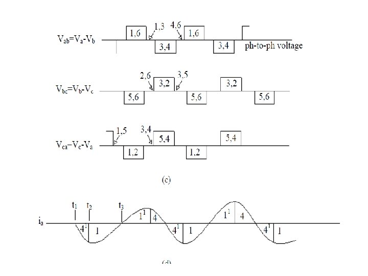
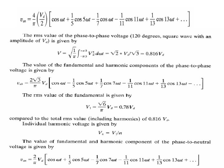
Fundamental and Harmonics for a Three-Phase Bridge Converter

§In two-level or multilevel converters, there is only one turn-on, turn-off per device per cycle. §With these converters, the ac output voltage can be controlled, by varying the width of the voltage pulses, and/or the amplitude of the dc bus voltage. Another approach is to have multiple pulses per half-cycle, and then vary the width of the pulses to vary the amplitude of the ac voltage. §The principal reason for doing so is to be able to vary the ac output voltage and to reduce the low-order harmonics. More pulses means more switching losses. §There also resonant PWM converter topologies that incorporate current-zero or voltage-zero type soft switching, in order to reduce the switching losses. Such converters are being increasingly utilized in some low power applications, but with the known topologies, they have not been justifiable at high power levels due to higher equipment cost.
")
Operation of a PWM converter with switching frequency of nine times the fundamental: (a) A phase-leg; (b) PWM waveforms.

CURRENT SOURCE CONVERTERS Diode Rectifier

Diode Rectifier or Diode Converter : Diode based line commutating converter just converts A. C. power to D. C. power without any control and also in doing so consumes some reactive power on the A. C. side. Thyristor Line Commutated Converter This utilizes A. C. system voltage for commutation of current from one valve to another. This converter can convert and controls active power in either direction, but in doing so consumes reactive power on the A. C. side. It can not supply reactive power to the A. C. system. Self Commutated Converter It is based on turn OFF devices like (GTOs, MTOs, IGBTs, etc) in which commutation of current from valve to valve takes place with the device turn OFF action and provision of A. C. capacitors to facilitate transfer of current from valve to valve. It also supplies or consumes the reactive power.

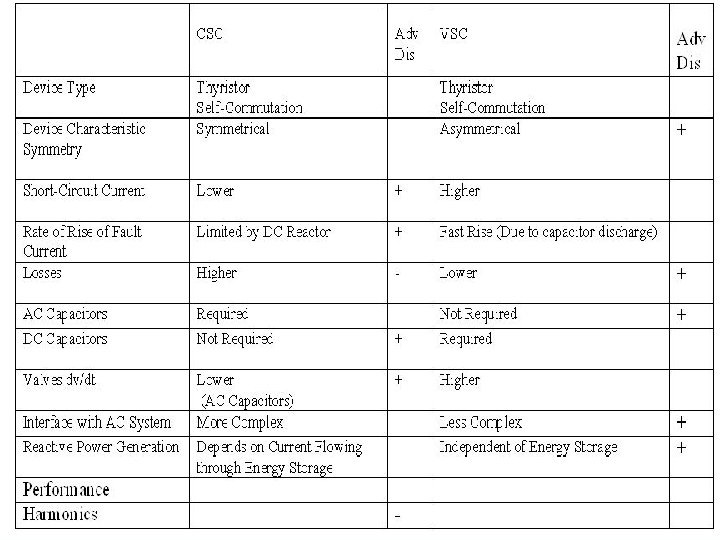
S. No. Voltage Source Converter Current Source Converter 1. The D. C. voltage always has one polarity, and the power reversal takes place through reversal of D. C. current polarity. Direct current always has one polarity and the power reversal takes place through reversal of D. C. voltage polarity 2. Turn OFF device(GTOs, IGBTs) based converters can be of either type i. e. current source or voltage source converter. Conventional Thyristor-based converters, being without turn OFF capability, can only be current source converters 3. Diode based voltage source converters are expensive. Diode based current source converters are the lowest converters if control of active power by the converter is not required. 4. The voltage source converter has high short circuit current The current sourced converter does not have high short circuit current 5. A. C capacitors required for Voltage source converter used small size of capacitors which are cheap. A. C capacitors required for the current stiff converters can be quite large and expensive. 6. In VSC, Losses are less as compared to CSC due to the absence of a series reactor. In CSC, Losses are much higher due to the presence of the series reactor.

Single Phase CSI With Ideal Switches
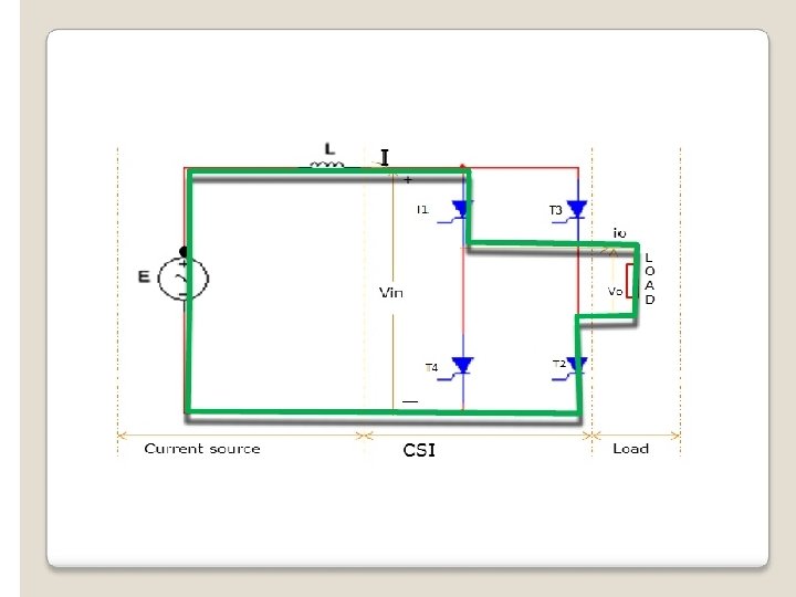
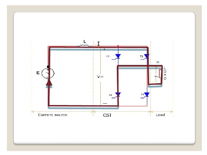
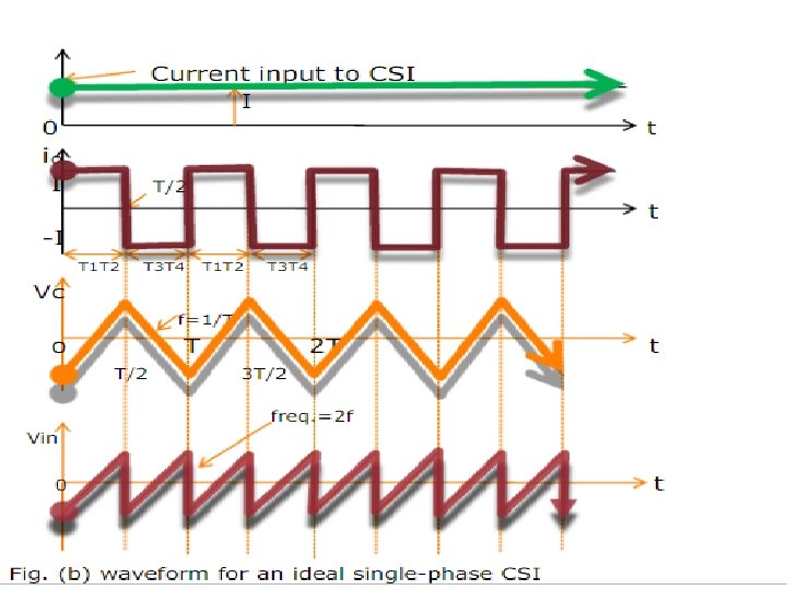
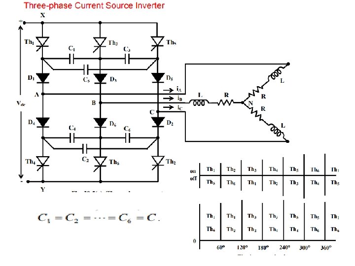

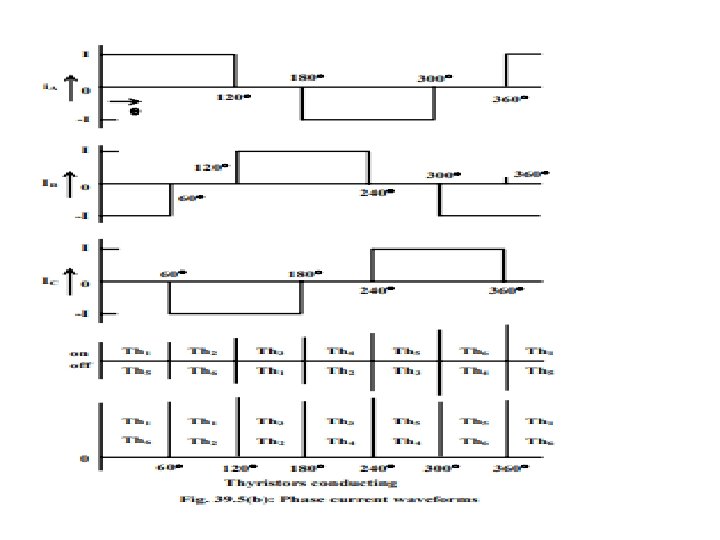
The diodes are needed in CSI, so as to prevent the capacitors from discharging into the load. The numbering scheme for the thyristors and diodes are same, as used in a three-phase VSI, with the thyristors being triggered in sequence as per number assigned.

THANK YOU
- Slides: 51