
Power Electronics Lecture11 Inverters Dr Imtiaz Hussain Associate


- Slides: 39
Power Electronics Lecture-11 Inverters Dr. Imtiaz Hussain Associate Professor email: imtiaz. hussain@faculty. muet. edu. pk URL : http: //imtiazhussainkalwar. weebly. com/ 1
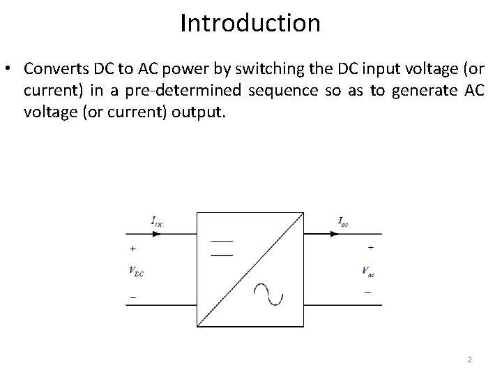
Introduction • Converts DC to AC power by switching the DC input voltage (or current) in a pre-determined sequence so as to generate AC voltage (or current) output. 2
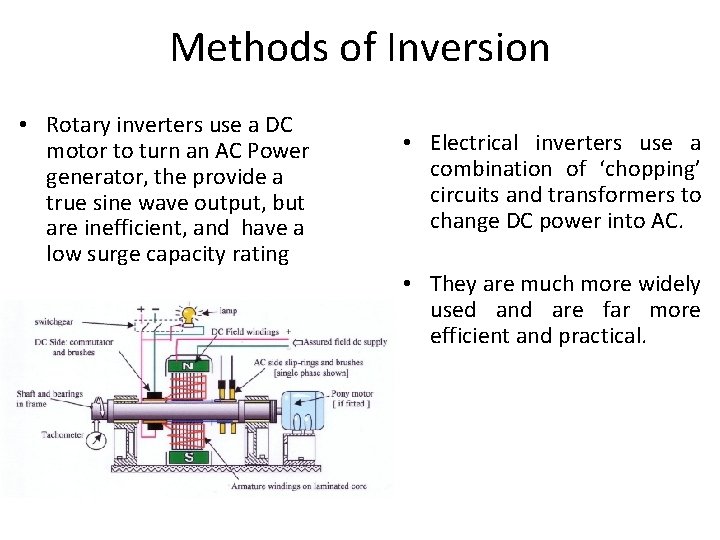
Methods of Inversion • Rotary inverters use a DC motor to turn an AC Power generator, the provide a true sine wave output, but are inefficient, and have a low surge capacity rating • Electrical inverters use a combination of ‘chopping’ circuits and transformers to change DC power into AC. • They are much more widely used and are far more efficient and practical.
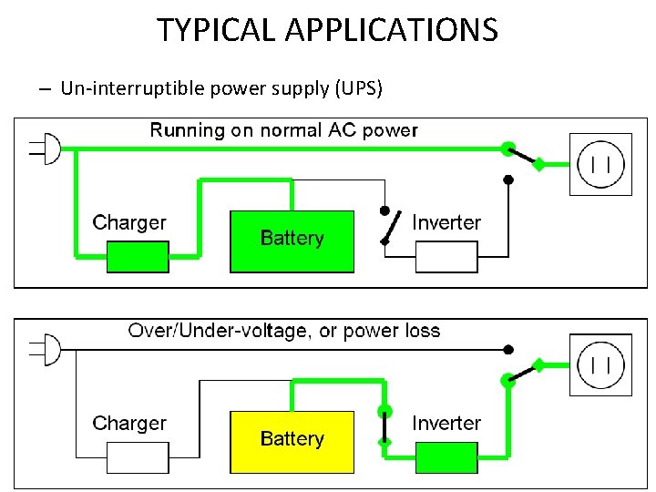
TYPICAL APPLICATIONS – Un-interruptible power supply (UPS) 4
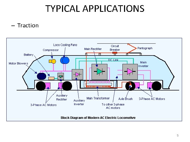
TYPICAL APPLICATIONS – Traction 5
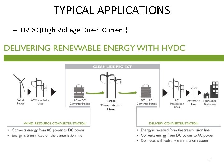
TYPICAL APPLICATIONS – HVDC (High Voltage Direct Current) 6
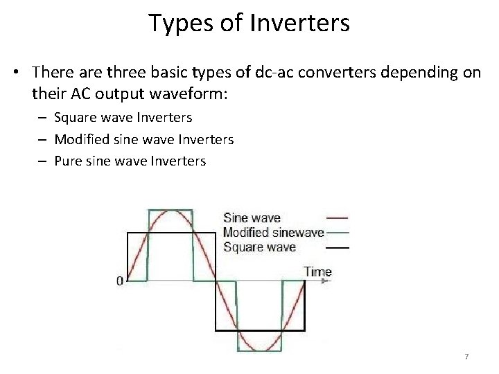
Types of Inverters • There are three basic types of dc-ac converters depending on their AC output waveform: – Square wave Inverters – Modified sine wave Inverters – Pure sine wave Inverters 7
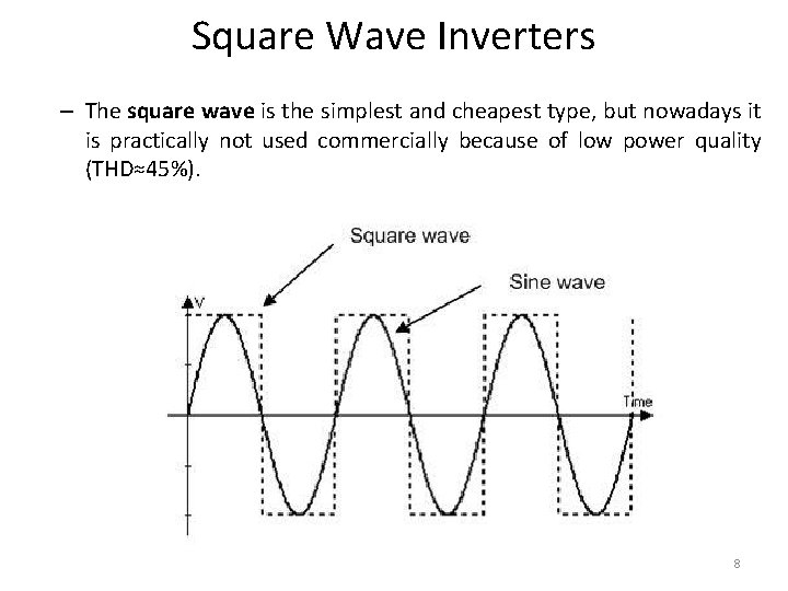
Square Wave Inverters – The square wave is the simplest and cheapest type, but nowadays it is practically not used commercially because of low power quality (THD≈45%). 8
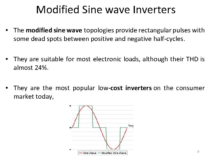
Modified Sine wave Inverters • The modified sine wave topologies provide rectangular pulses with some dead spots between positive and negative half-cycles. • They are suitable for most electronic loads, although their THD is almost 24%. • They are the most popular low-cost inverters on the consumer market today, 9
Pure Sine Wave Inverters – A true sine wave inverter produces output with the lowest total harmonic distortion (normally below 3%). – It is the most expensive type of AC source, which is used when there is a need for a sinusoidal output for certain devices, such as medical equipment, laser printers, stereos, etc. – This type is also used in grid-connected applications. 10
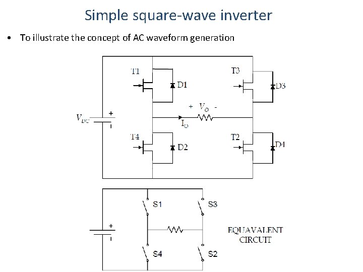
Simple square-wave inverter • To illustrate the concept of AC waveform generation
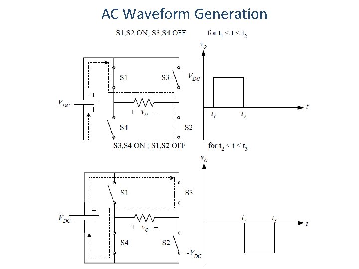
AC Waveform Generation
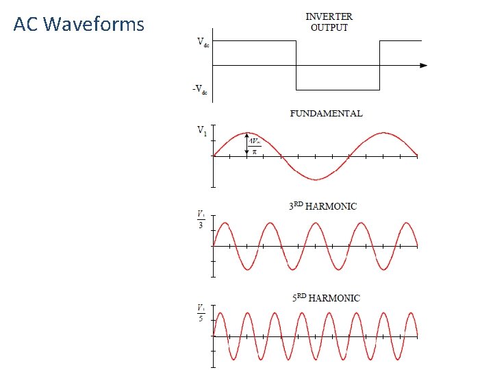
AC Waveforms
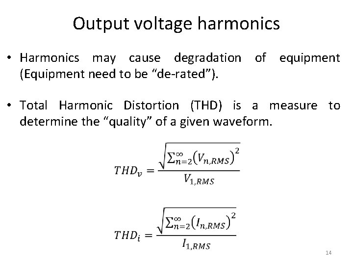
Output voltage harmonics • Harmonics may cause degradation of equipment (Equipment need to be “de-rated”). • Total Harmonic Distortion (THD) is a measure to determine the “quality” of a given waveform. 14
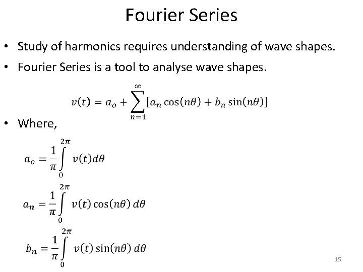
Fourier Series • Study of harmonics requires understanding of wave shapes. • Fourier Series is a tool to analyse wave shapes. • Where, 15
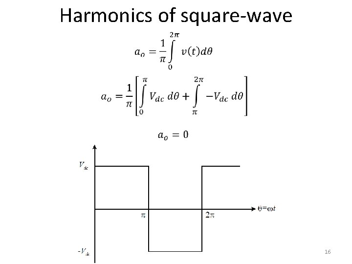
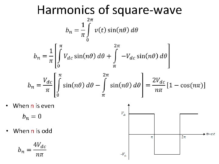
Harmonics of square-wave 16
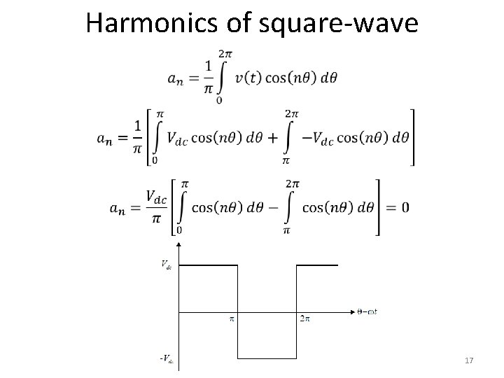
Harmonics of square-wave 17
Harmonics of square-wave • When n is even • When n is odd 18
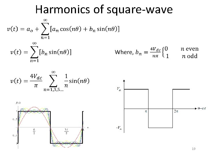
Harmonics of square-wave 19
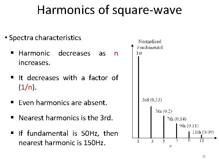
Harmonics of square-wave • Spectra characteristics § Harmonic decreases increases. as n § It decreases with a factor of (1/n). § Even harmonics are absent. § Nearest harmonics is the 3 rd. § If fundamental is 50 Hz, then nearest harmonic is 150 Hz. 20
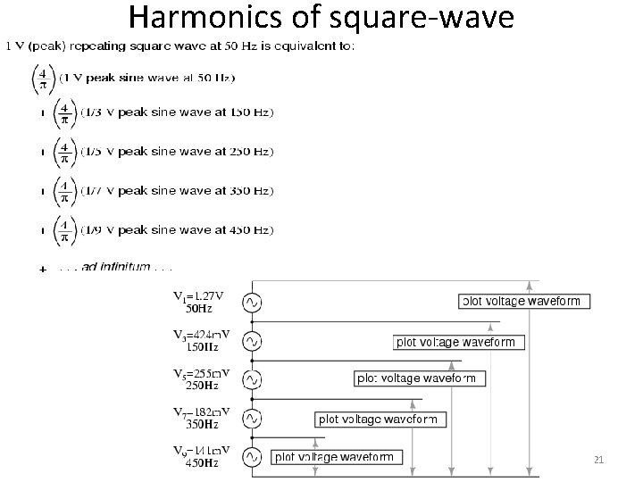
Harmonics of square-wave 21
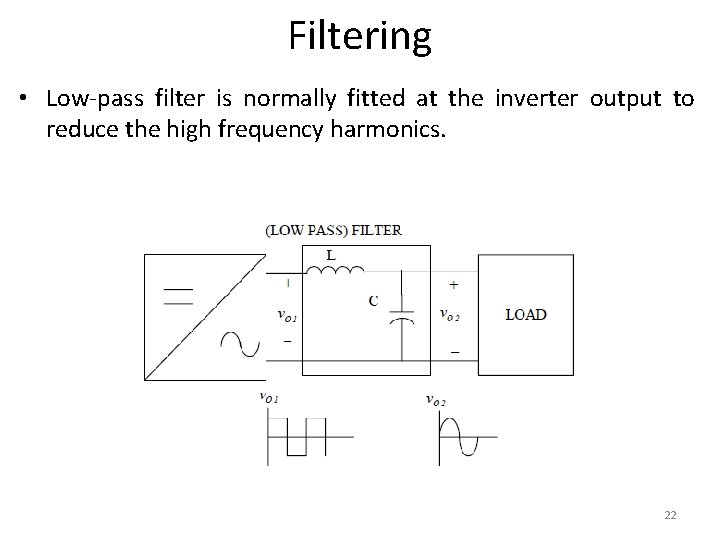
Filtering • Low-pass filter is normally fitted at the inverter output to reduce the high frequency harmonics. 22
Topologies of Inverters • Voltage Source Inverter (VSI) – Where the independently controlled ac output is a voltage waveform. – In industrial markets, the VSI design has proven to be more efficient, have higher reliability and faster dynamic response, and be capable of running motors without de-rating. • Current Source Inverter (CSI) – Where the independently controlled ac output is a current waveform. – These structures are still widely used in medium-voltage industrial applications, where high-quality voltage waveforms are required. 23
• Single phase voltage source inverters are of two types. – Single Phase Half Bridge voltage source inverters – Single Phase full Bridge voltage source inverters 24
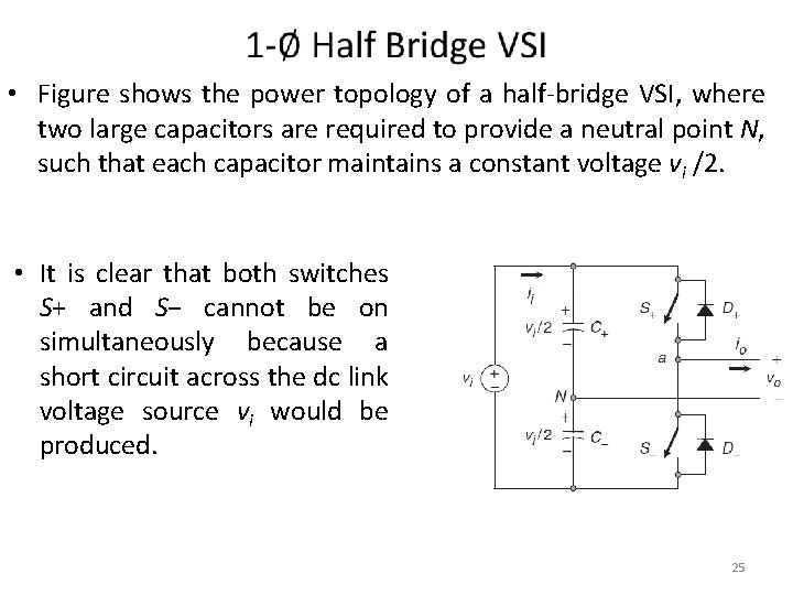
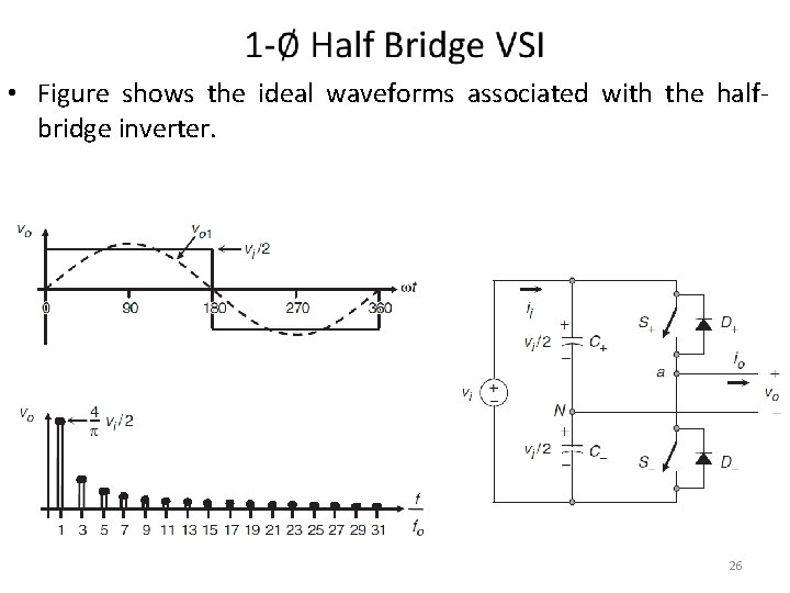
• Figure shows the power topology of a half-bridge VSI, where two large capacitors are required to provide a neutral point N, such that each capacitor maintains a constant voltage vi /2. • It is clear that both switches S+ and S− cannot be on simultaneously because a short circuit across the dc link voltage source vi would be produced. 25
• Figure shows the ideal waveforms associated with the halfbridge inverter. 26
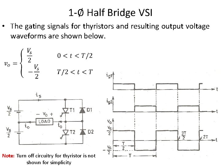
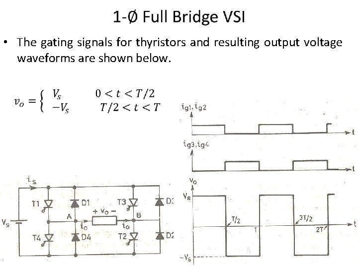
• The gating signals for thyristors and resulting output voltage waveforms are shown below. Note: Turn off circuitry for thyristor is not shown for simplicity 27
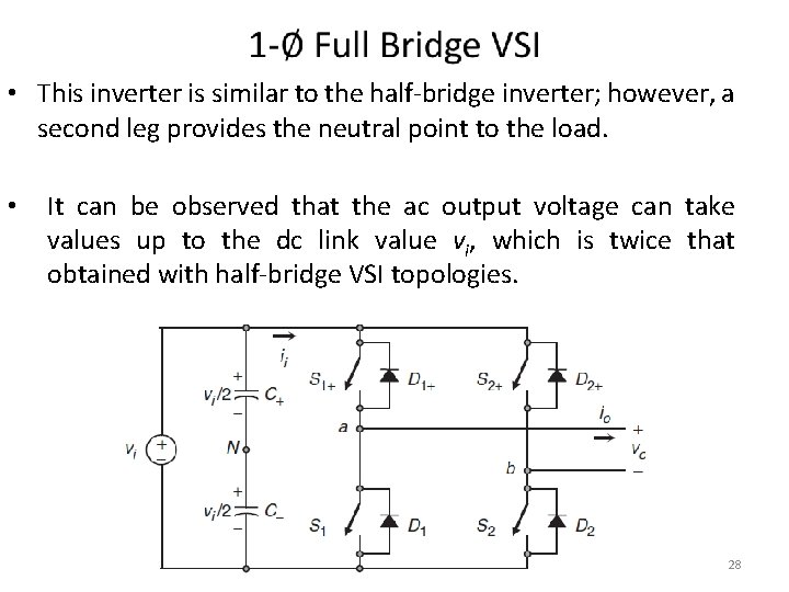
• This inverter is similar to the half-bridge inverter; however, a second leg provides the neutral point to the load. • It can be observed that the ac output voltage can take values up to the dc link value vi, which is twice that obtained with half-bridge VSI topologies. 28
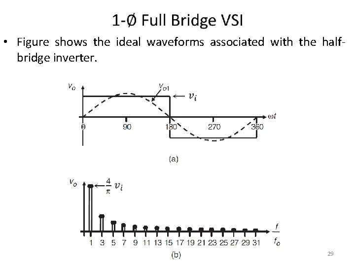
• Figure shows the ideal waveforms associated with the halfbridge inverter. 29
• The gating signals for thyristors and resulting output voltage waveforms are shown below. 30
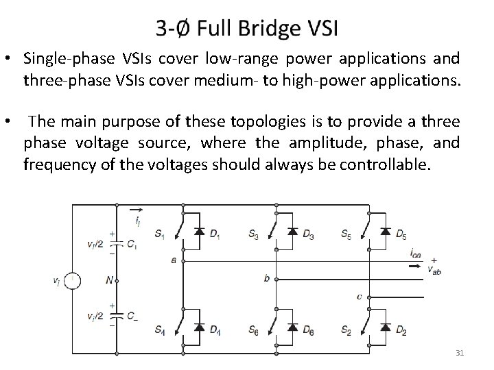
• Single-phase VSIs cover low-range power applications and three-phase VSIs cover medium- to high-power applications. • The main purpose of these topologies is to provide a three phase voltage source, where the amplitude, phase, and frequency of the voltages should always be controllable. 31
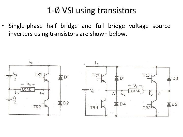
• Single-phase half bridge and full bridge voltage source inverters using transistors are shown below. 32
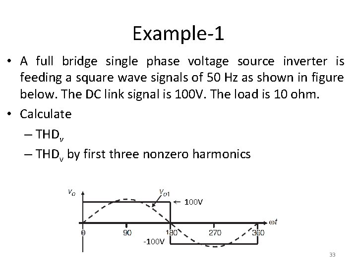
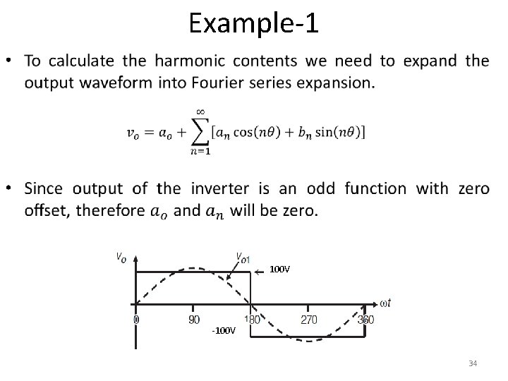
Example-1 • A full bridge single phase voltage source inverter is feeding a square wave signals of 50 Hz as shown in figure below. The DC link signal is 100 V. The load is 10 ohm. • Calculate – THDv by first three nonzero harmonics 100 V -100 V 33
Example-1 • 100 V -100 V 34
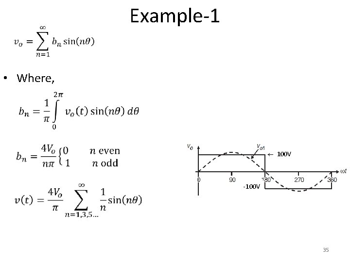
Example-1 • Where, 100 V -100 V 35
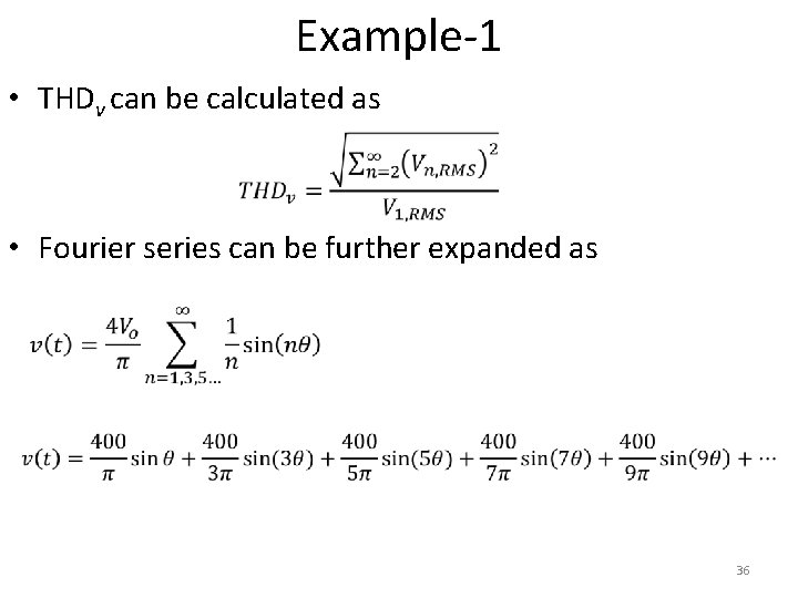
Example-1 • THDv can be calculated as • Fourier series can be further expanded as 36
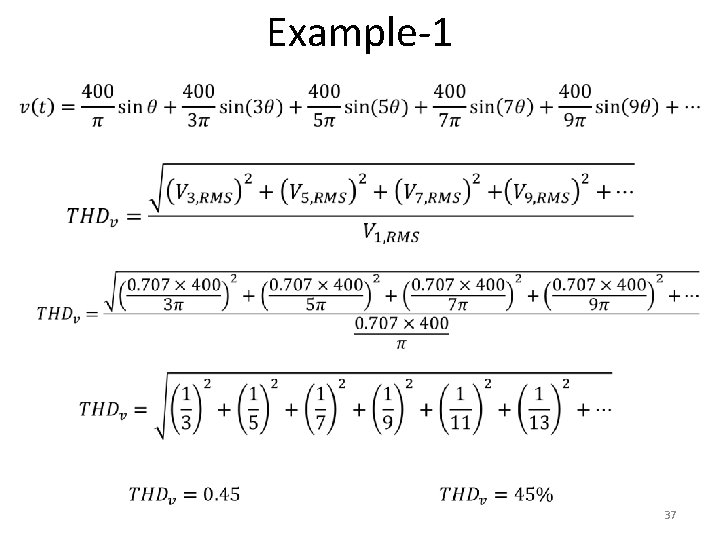
Example-1 37
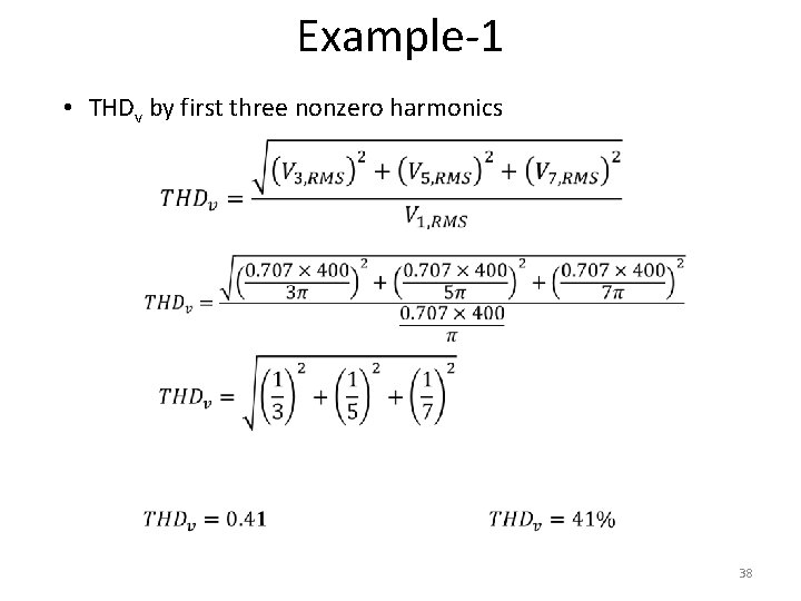
Example-1 • THDv by first three nonzero harmonics 38
To download this lecture visit http: //imtiazhussainkalwar. weebly. com/ END OF LECTURE-11 39