POWER ELECTRONICS DCDC CONVERTERS CHOPPERS PART 2 ILI
 PART 2 ILI SALWANI MOHAMAD EMT 369")
 Ø Transformer Models Ø Types of SMPS:")
 Weight and size reduction")


 Transformer (b) Ideal Model (c) Complete model (d) Most used for")


![Full-bridge Converter Operation Switch “pair”: [S 1 & S 2]; [S 3 & S](https://slidetodoc.com/presentation_image_h/a31d6cf86d48d95116a632cf93268b78/image-23.jpg "Full-bridge Converter Operation Switch “pair”: [S 1 & S 2]; [S 3 & S")


- Slides: 35
POWER ELECTRONICS DC-DC CONVERTERS (CHOPPERS) PART 2 ILI SALWANI MOHAMAD EMT 369
Content Ø Content Switch-mode Power Supply (SMPS) Ø Transformer Models Ø Types of SMPS: § Flyback Converter § Full-bridge Converter § Half-bridge Converter Ø Questions/Discussions Ø Ø (provided in separate sheet) SOURCES: “Power Electronics”, Daniel W. Hart, Mc-Graw Hill, “Power Electronics & Drives”, Lecture Notes, Dr. Zainal Salam, UTM
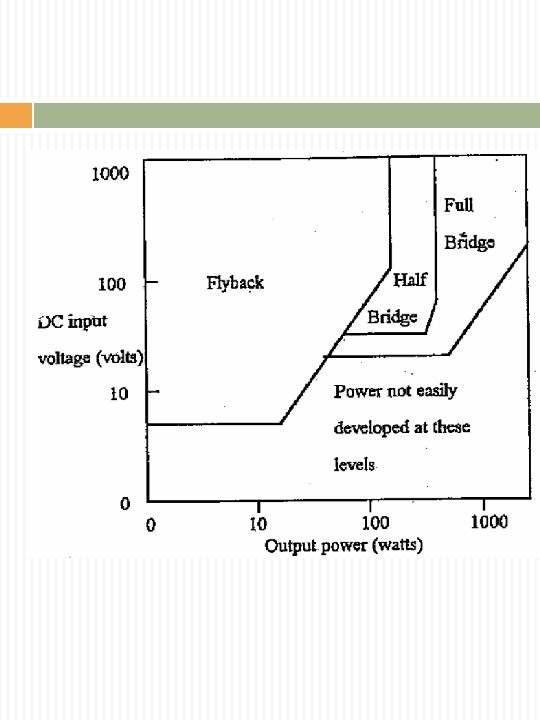
Switch-mode Power Supply Advantages over linear power Efficient (70 -95%) Weight and size reduction Disadvantages Complex design Electromagnetic interference (EMI) problems However above certain ratings, SMPS is the only feasible choice Types of SMPS Flyback Forward Push-pull Bridge (half and full)
Switch-mode Power Supply Block diagrams Basic Block diagram of linear power supply Basic Block diagram of SMPS
Switch-mode Power Supply Isolated topologies All isolated topologies include a transformer, and thus can produce an output of higher or lower voltage than the input by adjusting the turns ratio. For some topologies, multiple windings can be placed on the transformer to produce multiple output voltages. Some converters use the transformer for energy storage, while others use a separate inductor.
Switch-mode Power Supply Isolated types Source: Wikipedia
Once again…
Transformer Models 2 basic functions: I/O electrical isolation Step-up/step-down time varying voltages & currents I/O relationship of idealized model: Models: Ideal model Model used in most PE circuits
Transformer Models (a) Transformer (b) Ideal Model (c) Complete model (d) Most used for power electronics circuits
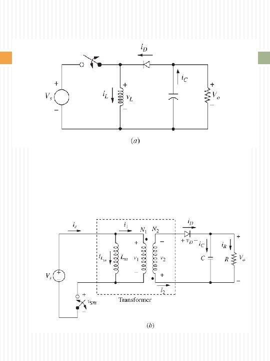
Flyback Converter Flyback converter is a buck-boost converter with the inductor split to form a transformer voltage ratio are multiplied with additional advantage of isolation Circuit Equivalent circuit includes magnetizing inductance
Flyback Converter Switch closed Switch open
Assumption for the analys The output capacitor is very large->? The switch and diode are ideal The circuit is operating in the steady s Duty ratio is D, being closed for time D And open for (1 -D)T
Flyback Converter Magnetizing inductance current Source current Diode current Capacitor current Transformer primary voltage
Flyback Converter Switch closed
Flyback Converter Switch open
Flyback Converter Steady-state Operation Note: I/O relationship is similar to buck- boost converter, with the present of transformer ratio Output depends to value of D (greater or less than input)
Flyback Converter Average Inductor Current
Flyback Converter Min & Max Inductor Current For continuous operation, ILm, min = 0
Flyback Converter Output Voltage Ripple Same as buck-boost converter Equivalent series resistance
Example Solution
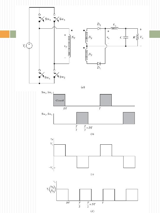
Full-bridge Converter Circuit D – duty ratio of each switch pair
Full-bridge Converter Operation Switch “pair”: [S 1 & S 2]; [S 3 & S 4] Each switch pair turn on at a time as shown. The other pair is off. When [S 1 & S 2] is closed – voltage across transformer primary is Vs When [S 3 & S 4] is closed – voltage across transformer primary is -Vs “AC voltage” is developed across the primary. Then transferred to secondary via high frequency transformers. On secondary side, diode pair is “high frequency full wave rectification”. The choke (L) and (C) acts like the “buck converter” circuit.
Full-bridge Converter Waveforms Switching sequence Voltage on transforme primary Voltage vx
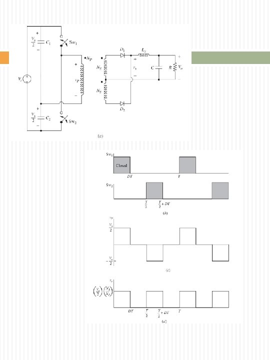
Half-bridge Converter
Half-bridge Converter Waveforms Switching sequence Voltage on transforme primary Voltage vx
Questions/Discussions Flyback Converter The flyback converter has the following parameters: Vs = 36 V, D = 0. 4, N 1/N 2 = 2, R = 20 Ω, Lm = 100 μH, C = 50 μF, and the switching frequency is 100 k. Hz. Determine: the output voltage the maximum and minimum inductor current the output voltage ripple A flyback converter has an input of 44 V, an output of 3 V, a duty ratio of 0. 32, and a switching frequency of 300 k. Hz. The load resistor is 1 Ω. Determine: the transformer turns ratio the transformer magnetizing inductance Lm such the minimum inductor current is 40% of the average.
Buck example 1 A buck converter is supplied from a 50 V battery source. Given L=400 u. H, C=100 u. F, R=20 Ohm, f=20 KHz and D=0. 4. Calculate: (a) output voltage (b) output voltage ri
Buck Example 2
Boost Example 1 The boost converter of Fig. 6 -8 has parameter Vs=20 V, D = 0. 6, R =12. 5Ω L = 10 μH, C = 40 μF, and the switching frequency is (a) (b) (c) (d) Determinethe output voltage. Determine the average, maximum, and minimum ind currents. Determine the output voltage ripple. Determine the average current in the diode. Assume ideal components.
Boost Example 2 A boost converter has an input of 5 V and an output of 25 W at 15 V. The minimum inductor current must be no less than 50% of the average. The output voltage Ripple must be less than 1%. The switching frequency 300 k. Hz. Determine the duty cycle ratio, min inductor v And minimum capacitor value.
Example Buck-Boost 1 Buck-boost has these parameters: Determine : i. Output Voltage = -16 V ii. Inductor current average = 5. 33 A, 4. iii. Inductor current = 7. 33 A, 2. 93 A maximum and minimum values iv. Output voltage ripple = 1%