POWER AND POWER FACTOR MEASUREMENT IN THREE PHASE


")


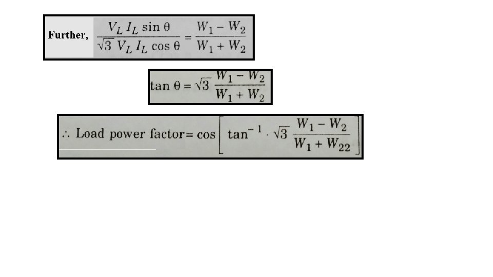
 And,")

- Slides: 8
POWER AND POWER FACTOR MEASUREMENT IN THREE PHASE CIRCUITS
• The various methods employed for the measurement of power in three phase circuit are: 1. One Wattmeter Method 2. Two Wattmeter Method 3. Three Wattmeter Method Out of these three method, the most widely used or preferred method is Two Wattmeter Method since this method gives the measurement of true power regardless of whether the load is balanced or unbalanced. In case of unbalanced load, the neutral of load must be isolated from the neutral of the source.
• Let’s consider a Star Connected Balanced Inductive Load (shown below)
• The three load phase voltages are Van, Vbn and Vcn respectively. Since the inductive load is considered, so, the corresponding phasor currents Ia , Ib and Ic are drawn lagging the respective phase voltages by a power factor angle θ. Let’s draw the phasor diagram: Since we are considering a balanced load Ia = Ib = Ic = IL (line current) And Vab = Vbc = Vca = VL (line voltage)
Reading of Wattmeter W 1 • Reading of Wattmeter W 2 Current through its current coil = Ia Current through its current coil = Ib Potential difference across the voltage coil = Vac Potential difference across the voltage coil = Vbc Now, So, reverse phasor Vcn and add to phasor Van to obtain Vac; this is shown in the phasor diagram. So, reverse phasor Vcn and add to phasor Vbn to obtain Vbc; this is shown in the phasor diagram. From the phasor diagram, it is clear that – Phase angle between Vac and Ia = (30 – θ) Phase angle between Vac and Ia = (30 + θ) So, Reading of Wattmeter W 1 = Vac and Ia cos (30 – θ) So, Reading of Wattmeter W 2 = Vbc and Ib cos (30 + θ)
So, Reading of Wattmeter W 1 = VL IL cos (300 – θ) And, Reading of Wattmeter W 2 = VL IL cos (300 + θ) Sum of two wattmeter readings: W 1 + W 2 =VL IL cos (300 – θ) +VL IL cos (300 + θ) =VL IL [cos 30 cosθ + sin 30 sinθ + cos 30 cosθ – sin 30 sinθ]
Effect or Variation of Load Power Factor on Wattmeter Readings