PostIGCSE Physics Course Experimental Physics using Data Loggers
 Dr")
 Fixed resistors for charge")


- Slides: 13
Post-IGCSE Physics Course: Experimental Physics using Data Loggers and Computers 14 Capacitor (Electromagnetism) Dr Andrew French P 5/6 Winchester College Last updated April/May 2017
Experimental setup Analogue voltmeter DC power supply (max 10 V) Fixed resistors for charge Capacitor (2 x 47, 000 m. F wired in parallel i. e. so total capacitance of 94, 000 m. F) Charge /discharge switch Fixed resistors for discharge
Two capacitors of capacitance 47, 000 m. F wired in parallel i. e. a total capacitance of 94, 000 m. F.
Measuring the resistance of the fixed resistors using a multimeter
Charging a capacitor using a DC source 1. Switch closed. Current flows through resistor and positive charge builds up on right capacitor plate. An equal amount of negative charge builds up on left plate. Switch 2. Electrical field set up between capacitor plates as no current can flow. Voltage V between the plates is V = Q/C where Q is the total charge deposited and C is the capacitance (‘charge per unit volt’) 3. As charge builds up on right plate, potential difference between capacitor and source reduces. This reduces the current flowing onto the plate. Eventually the voltage V becomes V 0 and hence no more current can flow. 3. Note the amount of charge which can be deposited depends on the resulting electrical field strength between the plates. Above the breakdown field strength, current will flow between the plates Dielectric Breakdown field strength /Vm-1 Air 3 x 10⁶ Mineral oil 15 x 106 Neoprene 16 x 106 Water 65 x 106 Mica 118 x 106
Charging a capacitor using a DC source capacitor charge, voltage relationship Ohm’s law Definition of current
Discharging a capacitor charge, voltage relationship Ohm’s law Definition of current, and negative since charge is discharged from plates Note V=V 0 when t = 0 So RC is a characteristic time for charging or discharging a capacitor
During charging phase, MATLAB keytime. m program is run, and a button on the keyboard is pressed when a fixed voltage is reached. 1, 2, 3, 4, 5, 6, 7, 8, 9. 5 V are an appropriate set. keytime. m stores the times of button presses to high precision. It is essentially a stopwatch with a split time facility. Once charging is ‘complete, ’ pressing ‘q’ and then return will stop the timer and export the timings into an Excel sheet. The process is repeated for the discharging phase. Charging and discharging is then repeated for the range of fixed resistors. From the recorded data, both the capacitance and the internal resistance of the circuit can then be calculated.
MATLAB keytime. m program.
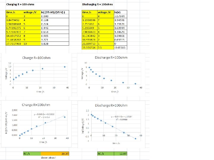
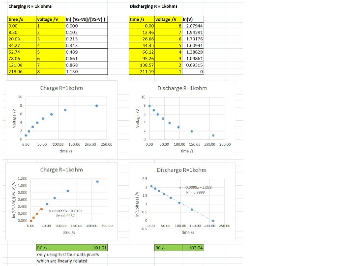
Discharge Obtain RC from gradient of ln. V vs t graph Charge Note V 0 is often not zero! Obtain RC from gradient of ln(. . . ) vs t graph
Significant timing errors? Might be worth repeating Calculate capacitance from gradient of resistance vs RC time graph, and internal resistance R 0 from intercept and gradient.