
PostAcceleration Study for Neutrino Superbeam at CSNS PresenterYang
Post-Acceleration Study for Neutrino Super-beam at CSNS Presenter:Yang Wu Mc. Master University Work conducted at IHEP
Contents �Introduction �Design goals �Overall design considerations �Scheme II �Comparison �Summary
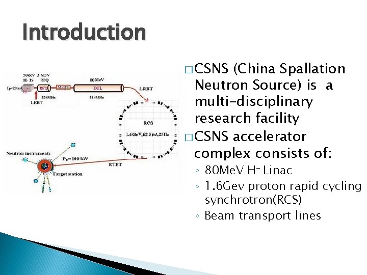
Introduction � CSNS (China Spallation Neutron Source) is a multi-disciplinary research facility � CSNS accelerator complex consists of: ◦ 80 Me. V H- Linac ◦ 1. 6 Gev proton rapid cycling synchrotron(RCS) ◦ Beam transport lines
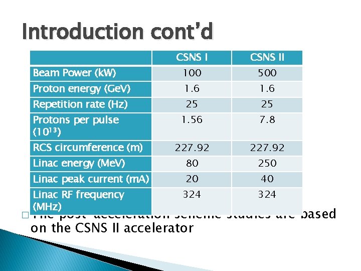
Introduction cont’d CSNS II Beam Power (k. W) 100 500 Proton energy (Ge. V) 1. 6 Repetition rate (Hz) 25 25 1. 56 7. 8 227. 92 Linac energy (Me. V) 80 250 Linac peak current (m. A) 20 40 324 Protons per pulse (1013) RCS circumference (m) Linac RF frequency (MHz) � The post-acceleration scheme studies are based on the CSNS II accelerator
Design goals � To extend CSNS to a super-beam facility which could be used for neutrino oscillation studies by adding a post-acceleration complex � To minimized the influence to CSNS applications, 10% of the RCS beam is used for post-acceleration. � To be competitive, the proton driver is to have an energy of 128 Ge. V and beam power of 4 MW.
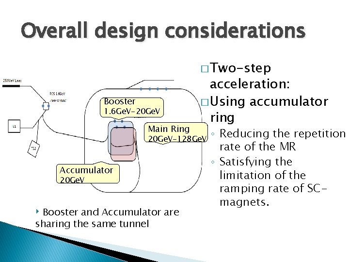
Overall design considerations � Two-step Booster 1. 6 Ge. V-20 Ge. V Main Ring acceleration: � Using accumulator ring 20 Ge. V-128 Ge. V Accumulator 20 Ge. V ‣ Booster and Accumulator are sharing the same tunnel ◦ Reducing the repetition rate of the MR ◦ Satisfying the limitation of the ramping rate of SCmagnets.
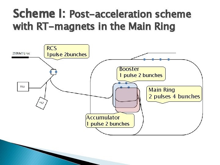
Scheme I: Post-acceleration scheme with RT-magnets in the Main Ring RCS 1 pulse 2 bunches Booster 1 pulse 2 bunches Main Ring 2 pulses 4 bunches Accumulator 1 pulse 2 bunches
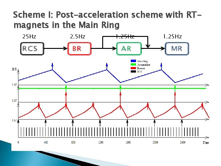
Scheme I: Post-acceleration scheme with RTmagnets in the Main Ring 25 Hz 2. 5 Hz 1. 25 Hz
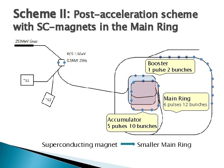
Scheme II: Post-acceleration scheme with SC-magnets in the Main Ring Booster 1 pulse 2 bunches Main Ring 6 pulses 12 bunches Accumulator 5 pulses 10 bunches Superconducting magnet Smaller Main Ring
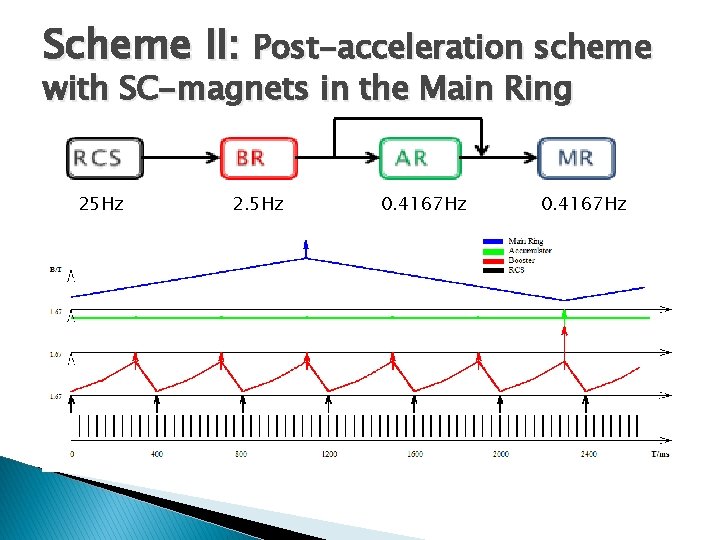
Scheme II: Post-acceleration scheme with SC-magnets in the Main Ring 25 Hz 2. 5 Hz 0. 4167 Hz
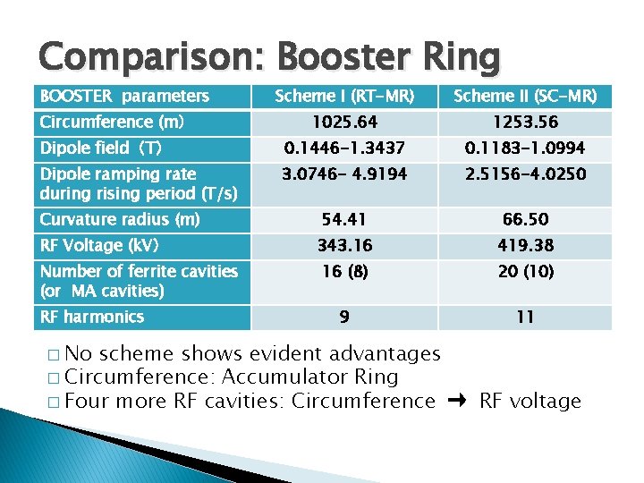
Comparison: Booster Ring BOOSTER parameters Scheme I (RT-MR) Scheme II (SC-MR) 1025. 64 1253. 56 Dipole field(T) 0. 1446 -1. 3437 0. 1183 -1. 0994 Dipole ramping rate during rising period (T/s) 3. 0746 - 4. 9194 2. 5156 -4. 0250 54. 41 66. 50 343. 16 419. 38 16 (8) 20 (10) 9 11 Circumference (m) Curvature radius (m) RF Voltage (k. V) Number of ferrite cavities (or MA cavities) RF harmonics � No scheme shows evident advantages � Circumference: Accumulator Ring � Four more RF cavities: Circumference → RF voltage
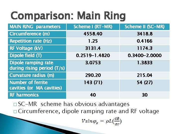
Comparison: Main Ring MAIN RING parameters Scheme I (RT-MR) Scheme II (SC-MR) Circumference (m) 4558. 40 3418. 8 Repetition rate (Hz) 1. 25 0. 4166 3131. 4 1174. 3 0. 2519 -1. 4820 0. 3400 -2. 0000 Dipole ramping rate during rising period (T/s) 3. 0753 1. 3833 Curvature radius (m) 290. 20 215. 04 143 (71) 54 (27) 40 30 RF Voltage (k. V) Dipole field (T) Number of ferrite cavities (or MA cavities) RF harmonics � SC-MR scheme has obvious advantages � Circumference, dipole ramping rate and RF voltage
Summary �A post-acceleration system for CSNS Neutrino Superbeam has been studied, with two slightly different schemes. � Both schemes exploit only 10% of CSNS/RCS beam. � The scheme with SC magnets in the MR is favored due to lower construction and operational cost. � With the beam energy of 128 Ge. V and beam power of 4 MW, CSNS superbeam will be very competitive in long-baseline neutrino physics.

Thank you for attention!
- Slides: 14