Positron annihilation spectroscopy PAS techniques allow us to

 q positron lifetime spectroscopy (LT,")


 12")


 P. Horodek et al. , Vacuum 138 (2017) 15– 21. 19")
, T 0 = 10 ns (100 MHz), the")


- Slides: 31
Positron annihilation spectroscopy Ø PAS techniques allow us to find defects with the size ranging from 0. 1 to 3 nm with the concentration up to 107 ppb Ø PAS makes possible the detection of defects in the wide range of depths from single nanometers up to milimeters 2 *) https: //www. hzdr. de/db/Cms? p. Nid=3581
Positron annihilation spectroscopy PAS techniques: q Doppler spectroscopy (DB) q positron lifetime spectroscopy (LT, PALS) Possibilities: q determination of defect concentration q evaluation of defect concentration profile q detection of the kind/size of defects Applications: q solid body physics q material and surface engineering q metals, semiconductors, thin layers 3 * http: //www. ifj. edu. pl/~mdryzek/
PALS Spectroscopy The annihilation rate λ - the reciprocal value of mean positron lifetime r 0 – electron radius, c – velocity of light Bi § electron density inside the defect is lower in comparison to bulk area what finds a reflect in the mean positron lifetime § e. g. for pure Fe τ = 110 ps in nondefected structure while positron trapped inside vacancy lives τ = 174 ps 4
Positron annihilation spectroscopy Ø digital spectrometer: Ba. F 2 - based detectors and APU 8702 unit Ø spectra including 106 counts were deconvoluted by LT code [*], substracting the background and the source components *) J. Kansy, Nucl. Instrum. Method. Phys. Res. A 374 (2) (1996) 235 5
EXPERIMENTAL TECHNIQUES: LT SPECTROSCOPY The positron lifetime spectroscopy Ø positron lifetime spectra consists of the exponential decay components Ø positron trapping in the open-volume defects leads to long lived components Ø longer life time due to lower electron density Ø analysis by non-linear fitting: lifetimes ti and intensities Ii The example of positron lifetime spectrum. 6
DB Spectroscopy The change of photon energy by relativistic Doppler effect in the laboratory system S parameter • ratio of area under the central part of 511 ke. V line to whole area below this line • defines the participation of e+e- pairs with low momentum • higher value means bigger concentration of such defects as vacancies 7
Positron Annihilation Spectroscopy The change of photon energy by relativistic Doppler effect in the laboratory system W parameter • ratio of area under the wing part of 511 ke. V line to whole area below this line • defines the participation of e+e- pairs with high momentum • together with S parameter gives limited information about kind of defects 8
Etching experiment 9
Etching experiment 10
THE CONVENTIONAL PAS EXPERIMENT HERE EXPERIMENTS WITH SLOW POSITRONS ARE REQUIRED !! There are some areas i. e. thin layers, ion implantation, semiconductors where the application of conventional PAS experiments is strongly limited 11
THE VARIABLE ENERGY POSITRON BEAM from i. Themba LABS (RSA) 12
THE VARIABLE ENERGY POSITRON BEAM Feature Value activity of 22 Na isotope ~30 m. Ci moderator frozen Ne (7 K) magnetic field 100 Gs vacuum conditions 10 -9 Torr intensity ~106 e+/s energy range 50 e. V ÷ 40 ke. V diameter of the flux 5 mm 13
THE VARIABLE ENERGY POSITRON BEAM 14
THE VARIABLE ENERGY POSITRON BEAM 15
THE VARIABLE ENERGY POSITRON BEAM 16
THE VARIABLE ENERGY POSITRON BEAM 17
THE VARIABLE ENERGY POSITRON BEAM 18
Results: Cu *) P. Horodek et al. , Vacuum 138 (2017) 15– 21. 19
PALS SPECTROSCOPY WITH BEAM Function URF(t), T 0 = 10 ns (100 MHz), the positron energy E 0 = 150 e. V and LA = 20, 15, 12 cm (curves from the top to the bottom); x = t/T 0 The voltage pulse (V) in the accelerating gap of the RF system for the original form (solid curve) and composed with to the first three harmonics (dashed curve). 20
PALS SPECTROSCOPY WITH BEAM 21
PALS SPECTROSCOPY WITH BEAM 22
PALS SPECTROSCOPY WITH BEAM 23
ION ETCHING SYSTEM Makhov profile 24
ION ETCHING SYSTEM Technical data Energy range 0. 15 ke. V - 5 ke. V Gases Ar and reactive gases (O 2, H 2 hydrocarbons with reduced lifetime) Scan area 10 mm x 10 mm Current density up to 4 m. A / cm 2 Beam current > 1 μA Working pressure 10 -8 mbar (with max beam current) 25
ION ETCHING SYSTEM 26
Cooperations: • Studies of materials for usage in IV type nuclear reactors q Institute of Nuclear Physics PAS, Kracow, Poland q Institute of Radiation Problems NAS, Baku, Azerbaijan q Institute for Nuclear Research and Nuclear Energy, Sofia, Bulgaria q University of Szczecin, Poland q JINR, FLNR q Belarusian State University, Belarus q Sumy State University, Ukraine • Studies on high irradiation resistivity materials, surface nanostructurization – thin layers of Zr/Nb q PTU Tomsk, Russia • Surface modification by ion implanatation in semiconductors and MOS structures q UMCS Lublin, Poland q CNT Hochiminh, Vietnam q Institute of Physics, VAST, Hanoi, Vietnam 27
Cooperations: • Surface modification of zeolite ZSM-5 by irradiation q CNT Hochiminh, Vietnam • Study of defects in optical materials - Li. Ga. Se 2 , bromides and chlorides APb 2 C 5 type, where A=K or Rb, and C=Cl or Br q IGM SB RAS and NSU, Novosibirsk, Russia q JINR, FLNP • Study of destruction proces – cavitation, wear, corrosion q Institute of Nuclear Physics PAS, Kracow, Poland q Northern Arctic Federal University, Arkhangelsk, Russia • The role of defects in magnetic properties in nanopwoders -Ba. Ti. O 3 – VSU, Voronezh, Russia • Mechanical modification of materials – sandblasting, hydrostatic extrusion, surface modification attrition techniques q Institute of Nuclear Physics PAS, Kracow, Poland q UE, Kracow, Poland q AGH University, Kracow, Poland q Rzeszów University of Technology, Poland 28
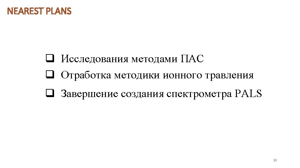
NEAREST PLANS Doppler Coincidence Spectroscopy - coincident detection of second annihilation reduces background - use of a second Ge detector improves energy resolution of system 29