
PON Architecture for Wireless Backhaul Paul Wilford October
PON Architecture for Wireless Backhaul Paul Wilford October 28, 2009 -
1 2 The mobile backhaul problem All Rights Reserved © Alcatel-Lucent 2009
The mobile backhaul problem Current Wireless Carrier Environment § Increased bandwidth demands § Due to more advanced users and handsets § Mobile broadband (killer app) § TDM Backhaul is not efficient for packet data § Doesn’t fit well in traditional T 1 Architecture 3 All Rights Reserved © Alcatel-Lucent 2009
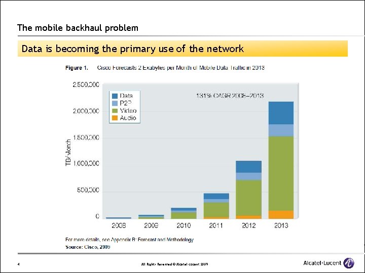
The mobile backhaul problem Data is becoming the primary use of the network 4 All Rights Reserved © Alcatel-Lucent 2009
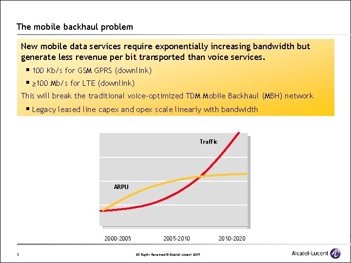
The mobile backhaul problem New mobile data services require exponentially increasing bandwidth but generate less revenue per bit transported than voice services. § 100 Kb/s for GSM GPRS (downlink) § ≥ 100 Mb/s for LTE (downlink) This will break the traditional voice-optimized TDM Mobile Backhaul (MBH) network § Legacy leased line capex and opex scale linearly with bandwidth Traffic ARPU 2000 -2005 5 2005 -2010 All Rights Reserved © Alcatel-Lucent 2009 2010 -2020

2 6 Landscape of today All Rights Reserved © Alcatel-Lucent 2009
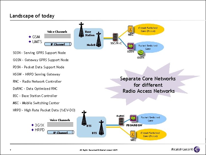
Landscape of today Voice Channels GSM UMTS IP Channel Base Station Node. B • SGSN – Serving GPRS Support Node • GGSN – Gateway GPRS Support Node • PDSN – Packet Data Support Node • HSGW – HRPD Serving Gateway Separate Core Networks for different Radio Access Networks • RNC – Radio Network Controller • Do. RNC – Data Optimized RNC • BSC – Base Station Controller • MSC – Mobile Switching Center • HRPD – High Rate Packet Data (1 x. EV-DO) Do. RNC Voice Channels 3 G 1 X HRPD 7 PDSN/HSGW BTS IP Channel BTS All Rights Reserved © Alcatel-Lucent 2009
Landscape of today Examples of customer deployments – Customer ‘X’ primarily uses ATM for backhaul. The overall strategy is to seek higher-capacity, lower-cost solutions as the more data-centric technologies such as HSDPA drive capacity requirements. The target state architecture is one that is flexible and can scale as capacity demand increases. Some solutions being considered include fiber to the cell site and bonded copper. Customer ‘X’ has a combination of GSM/UMTS networks and will need to integrate backhaul for all networks as it migrates from GSM to UMTS to LTE. 8 All Rights Reserved © Alcatel-Lucent 2009
Landscape of today Examples of customer deployments – Customer ‘Y’s backhaul strategy consists of delivering Ethernet over the existing copper infrastructure with a migration to fiber-based Ethernet backhaul services. Customer ‘Y’ plans to leverage its Fiber to the Premise (FTTP) network with pseudowire to provide backhaul services. 9 All Rights Reserved © Alcatel-Lucent 2009

3 10 Landscape of Tomorrow All Rights Reserved © Alcatel-Lucent 2009
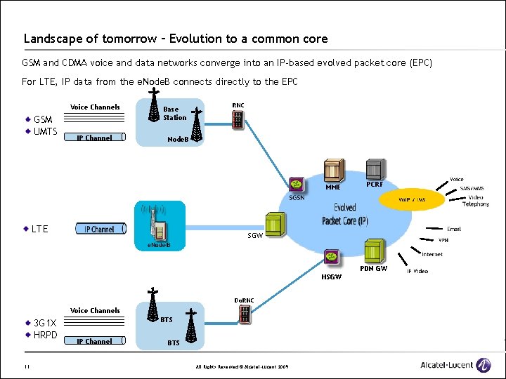
Landscape of tomorrow – Evolution to a common core GSM and CDMA voice and data networks converge into an IP-based evolved packet core (EPC) For LTE, IP data from the e. Node. B connects directly to the EPC Voice Channels GSM UMTS IP Channel Base Station RNC Node. B MME LTE PCRF SGW PDN GW HSGW Do. RNC Voice Channels 3 G 1 X HRPD 11 BTS IP Channel BTS All Rights Reserved © Alcatel-Lucent 2009
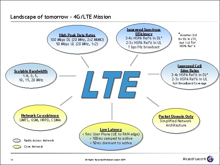
Landscape of tomorrow - 4 G/LTE Mission High Peak Data Rates 100 Mbps DL (20 MHz, 2 x 2 MIMO) 50 Mbps UL (20 MHz, 1 x 2) Improved Spectrum Efficiency 3 -4 x HSPA Rel’ 6 in DL* 2 -3 x HSPA Rel’ 6 in UL 1 bps/Hz broadcast Full Broadband Coverage Network Co-existence UMTS, GSM, HRPD, CDMA Core Network 12 for DL in LTE, but 1 x 2 for HSPA Rel’ 6 Improved Cell Edge Rates 3 -4 x HSPA Rel’ 6 in DL* 2 -3 x HSPA Rel’ 6 in UL Scalable Bandwidth 1. 4, 3, 5, 10, 15, 20 MHz Radio Access Network *Assumes 2 x 2 Packet Domain Only Simplified Network Architecture Low Latency < 5 ms User Plane (UE to RAN edge) < 100 ms camped to active < 50 ms dormant to active All Rights Reserved © Alcatel-Lucent 2009
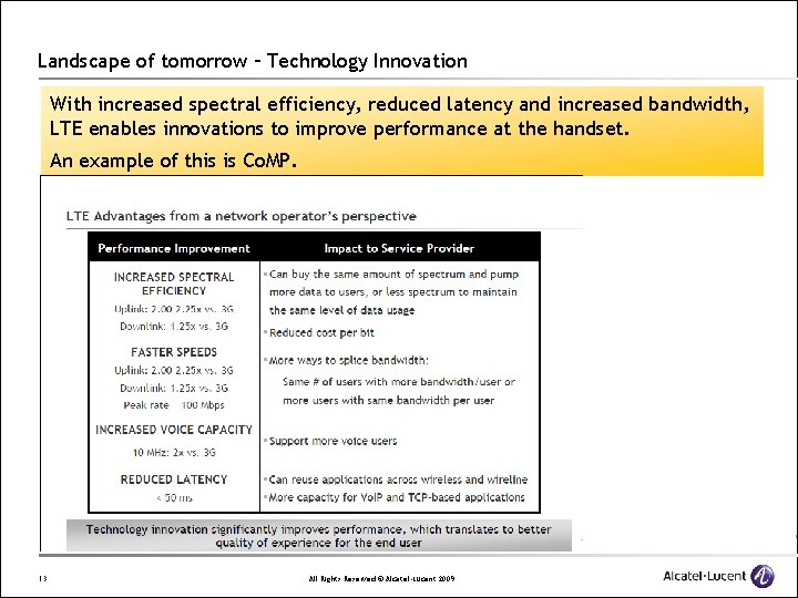
Landscape of tomorrow – Technology Innovation With increased spectral efficiency, reduced latency and increased bandwidth, LTE enables innovations to improve performance at the handset. An example of this is Co. MP. 13 All Rights Reserved © Alcatel-Lucent 2009
4 14 What is Co. MP? All Rights Reserved © Alcatel-Lucent 2009
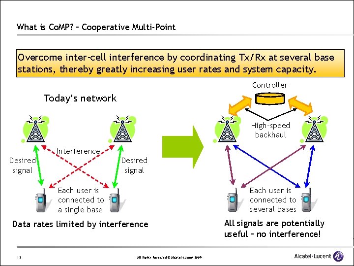
What is Co. MP? – Cooperative Multi-Point Overcome inter-cell interference by coordinating Tx/Rx at several base stations, thereby greatly increasing user rates and system capacity. Controller Today’s network High-speed backhaul Interference Desired signal Each user is connected to a single base Each user is connected to several bases Data rates limited by interference All signals are potentially useful – no interference! 15 All Rights Reserved © Alcatel-Lucent 2009
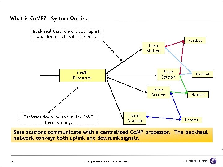
What is Co. MP? - System Outline Backhaul that conveys both uplink and downlink baseband signal. Handset Base Station Co. MP Processor Base Station Performs downlink and uplink Co. MP beamforming. Base Station Handset Base stations communicate with a centralized Co. MP processor. The backhaul network conveys both uplink and downlink signals. 16 All Rights Reserved © Alcatel-Lucent 2009
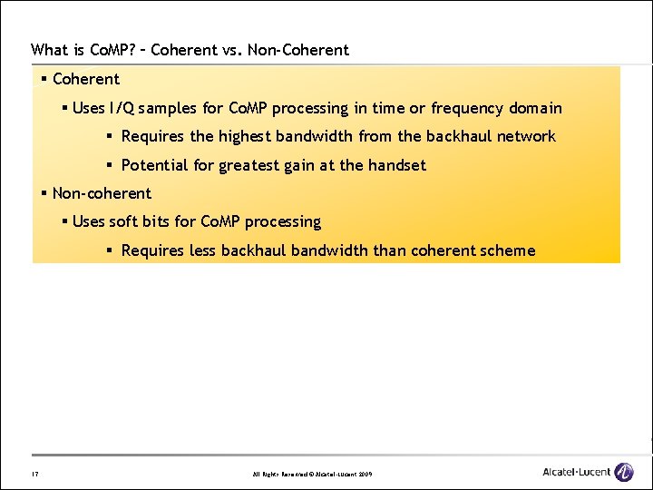
What is Co. MP? – Coherent vs. Non-Coherent § Uses I/Q samples for Co. MP processing in time or frequency domain § Requires the highest bandwidth from the backhaul network § Potential for greatest gain at the handset § Non-coherent § Uses soft bits for Co. MP processing § Requires less backhaul bandwidth than coherent scheme 17 All Rights Reserved © Alcatel-Lucent 2009
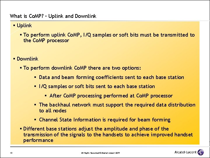
What is Co. MP? – Uplink and Downlink § Uplink § To perform uplink Co. MP, I/Q samples or soft bits must be transmitted to the Co. MP processor § Downlink § To perform downlink Co. MP there are two options: § Data and beam forming coefficients sent to each base station § I/Q samples or soft bits sent to each base station § After Co. MP processing performed at Co. MP processor § The backhaul network must support the required data distribution to all nodes § Channel State Information is required for beam forming § Different base stations adjust the amplitude and phase of the transmission of the signals to the handsets to achieve improved handset performance 18 All Rights Reserved © Alcatel-Lucent 2009
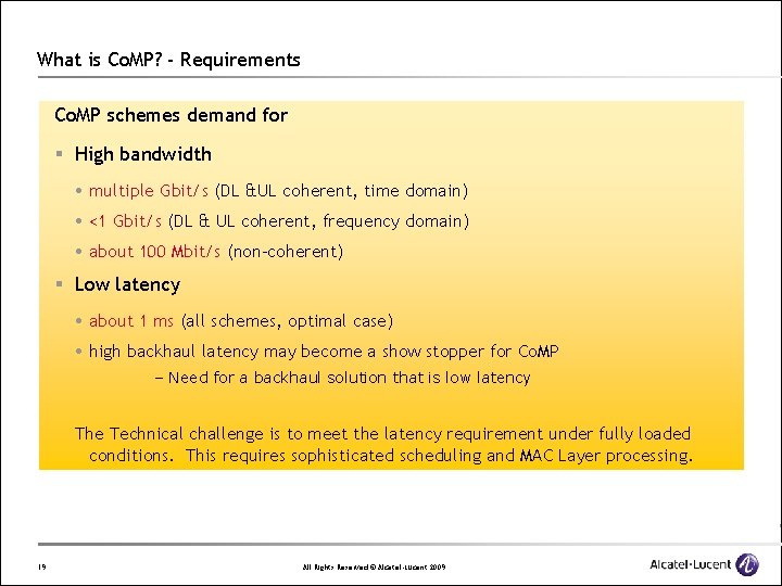
What is Co. MP? - Requirements Co. MP schemes demand for § High bandwidth multiple Gbit/s (DL &UL coherent, time domain) <1 Gbit/s (DL & UL coherent, frequency domain) about 100 Mbit/s (non-coherent) § Low latency about 1 ms (all schemes, optimal case) high backhaul latency may become a show stopper for Co. MP – Need for a backhaul solution that is low latency The Technical challenge is to meet the latency requirement under fully loaded conditions. This requires sophisticated scheduling and MAC Layer processing. 19 All Rights Reserved © Alcatel-Lucent 2009
5 20 Different PON technologies All Rights Reserved © Alcatel-Lucent 2009
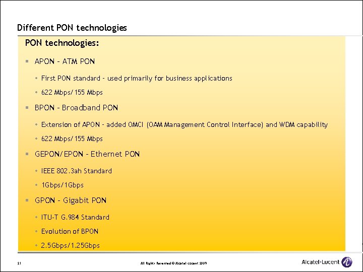
Different PON technologies: § APON – ATM PON First PON standard – used primarily for business applications 622 Mbps/155 Mbps § BPON – Broadband PON Extension of APON – added OMCI (OAM Management Control Interface) and WDM capability 622 Mbps/155 Mbps § GEPON/EPON – Ethernet PON IEEE 802. 3 ah Standard 1 Gbps/1 Gbps § GPON – Gigabit PON ITU-T G. 984 Standard Evolution of BPON 2. 5 Gbps/1. 25 Gbps 21 All Rights Reserved © Alcatel-Lucent 2009
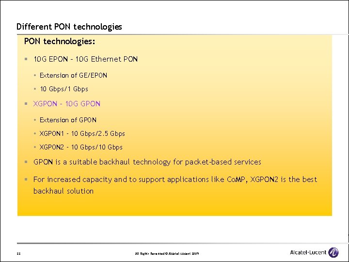
Different PON technologies: § 10 G EPON – 10 G Ethernet PON Extension of GE/EPON 10 Gbps/1 Gbps § XGPON – 10 G GPON Extension of GPON XGPON 1 – 10 Gbps/2. 5 Gbps XGPON 2 – 10 Gbps/10 Gbps § GPON is a suitable backhaul technology for packet-based services § For increased capacity and to support applications like Co. MP, XGPON 2 is the best backhaul solution 22 All Rights Reserved © Alcatel-Lucent 2009
6 23 Synchronization All Rights Reserved © Alcatel-Lucent 2009
Synchronization: Problems with synchronization § Base station radio interface typically requires some level of synchronization § Frequency accuracy § Time/phase accuracy § Base station backhaul interface (typically legacy base stations) may be synchronous (T 1/E 1) § Synchronization considerations § Relative phase stability § Mobile hand-off between base stations § Coherent Co. MP § Core network may or may not be synchronous § (Traditional) Ethernet, Synchronous Ethernet, SONET, etc. § Separate timing distribution network may or may not exist § GPS, NTR, etc. 24 All Rights Reserved © Alcatel-Lucent 2009
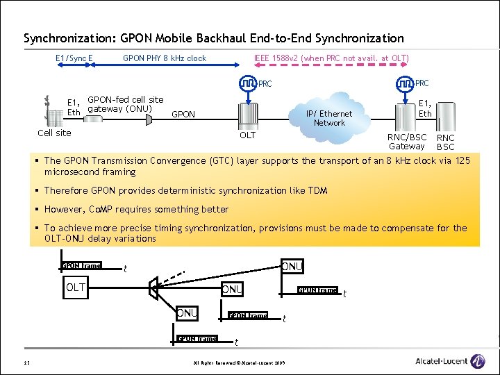
Synchronization: GPON Mobile Backhaul End-to-End Synchronization E 1/Sync E GPON PHY 8 k. Hz clock IEEE 1588 v 2 (when PRC not avail. at OLT) PRC E 1, GPON-fed cell site Eth gateway (ONU) GPON IP/ Ethernet Network Cell site OLT E 1, Eth RNC/BSC Gateway RNC BSC § The GPON Transmission Convergence (GTC) layer supports the transport of an 8 k. Hz clock via 125 microsecond framing § Therefore GPON provides deterministic synchronization like TDM § However, Co. MP requires something better § To achieve more precise timing synchronization, provisions must be made to compensate for the OLT-ONU delay variations GPON frame ONU t OLT ONU GPON frame 25 GPON frame t t All Rights Reserved © Alcatel-Lucent 2009 t
7 26 The MAC Layer All Rights Reserved © Alcatel-Lucent 2009
The MAC Layer: GPON § GPON Qo. S is maintained through transmission containers (T-CONTs) § T-CONT classes § Type 1 – fixed bandwidth § Type 2 – assured bandwidth § Type 3 – allocated bandwidth + non-assured bandwidth § Type 4 – best effort § Type 5 – superset of all of the above § Scheduling algorithm at the GEM Layer guarantees that transmission container bandwidth and latency guarantees are satisfied under fully loaded conditions § Dynamic Bandwidth Allocation § Maximum fiber bandwidth utilization § Based on queue status from ONUs § Security (via AES) § FEC 27 All Rights Reserved © Alcatel-Lucent 2009
The MAC Layer: Backhaul challenges § Co. MP data processed and sent to downstream path for scheduling/reflection to ONUs § Very low latency requirement of 1 ms § Handoff between e. Node. Bs requires tighter synchronization at base stations § OLT must send additional information to ONUs so they know neighboring ONU timing for handoffs § FEC at 10 Gbps § Completing R-S computations for 10 Gbps within 125 us is challenging 28 All Rights Reserved © Alcatel-Lucent 2009
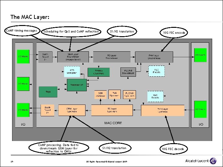
The MAC Layer: Co. MP timing messages Scheduling for Qo. S and Co. MP reflection Co. MP processing. Data fed to downstream GEM Layer for reflection to ONUs 29 S 1/X 2 translation All Rights Reserved © Alcatel-Lucent 2009 10 G FEC encode 10 G FEC decode

8 30 Conclusions All Rights Reserved © Alcatel-Lucent 2009
Conclusions XGPON 2: § Is a backhaul solution that can accommodate growth in bandwidth demand § Is a backhaul solution that connects to the simplified network architecture § Is a backhaul solution that can integrate data from 2 G, 3 G and LTE networks § Is a backhaul solution that can handle the uplink and downlink data distribution requirements for applications like Co. MP § Is a backhaul solution that is synchronous and is compatible with IEEE 1588 v 2 synchronization through packet networks § Is a backhaul solution that contains efficient scheduling in the MAC layer for maintaining Qo. S under fully loaded conditions 31 All Rights Reserved © Alcatel-Lucent 2009

Thank You! 32 All Rights Reserved © Alcatel-Lucent 2009
Backup Slides 33 All Rights Reserved © Alcatel-Lucent 2009
The MAC Layer: ONU block diagram 34 All Rights Reserved © Alcatel-Lucent 2009
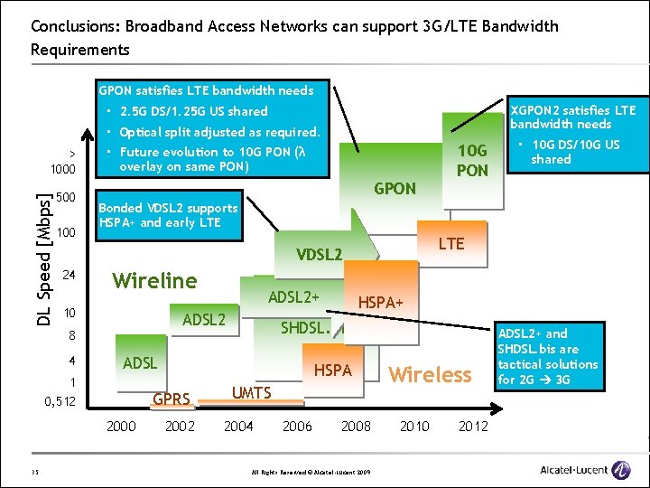
Conclusions: Broadband Access Networks can support 3 G/LTE Bandwidth Requirements GPON satisfies LTE bandwidth needs XGPON 2 satisfies LTE bandwidth needs • 2. 5 G DS/1. 25 G US shared • Optical split adjusted as required. DL Speed [Mbps] > 1000 500 100 • Future evolution to 10 G PON (λ overlay on same PON) GPON Wireline 10 LTE HSPA GPRS 2000 HSPA+ SHDSL. bis ADSL 1 0, 512 35 ADSL 2+ ADSL 2 8 4 • 10 G DS/10 G US shared Bonded VDSL 2 supports HSPA+ and early LTE VDSL 2 24 10 G PON 2002 UMTS 2004 2006 2008 All Rights Reserved © Alcatel-Lucent 2009 Wireless 2010 2012 ADSL 2+ and SHDSL. bis are tactical solutions for 2 G 3 G
- Slides: 35