Polymer thin films by CVD and PVD sami

Polymer thin films by CVD and PVD sami. franssila@aalto. fi

CVD on Nylon fabric CVD polymers part is based on Alf & Gleason article. Alf & Gleason, Adv. Mater. 2010, 22, 1993– 2027

PECVD • In PECVD, plasma excitation of the vapor phase creates the radical species. [11] • However, the degree to which organic functionality ispreserved often improves by decreasing the plasma power through strategies such as • pulsing the plasma excitation[12– 20] or • performing the deposition downstream of the active plasma region

Too long and/or high energy pulses destroy polymer functionality
 (PHEMA) was deposited by pulsed PECVD while")
Hydrogels by PECVD Hydrogel poly(2 -hydroxyethyl methacrylate) (PHEMA) was deposited by pulsed PECVD while preserving the functionality and biocompatibility of the film. Approximately 80% retention of the surface hydroxyl groups, resulting in a sessile drop contact angle of 17 o at a deposition rate of 13. 4 nm/min

Dangling bonds • if these species are not fully reacted during CVD growth, the resultant polymer film contains socalled dangling bond defects. • Once exposed to the air, these defects can further react with oxygen and water, altering the film properties from their as-deposited state.
")
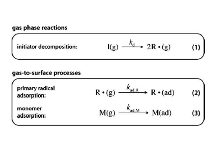
i. CVD (initiator CVD)

i. CVD reactor

PAN nanotubes

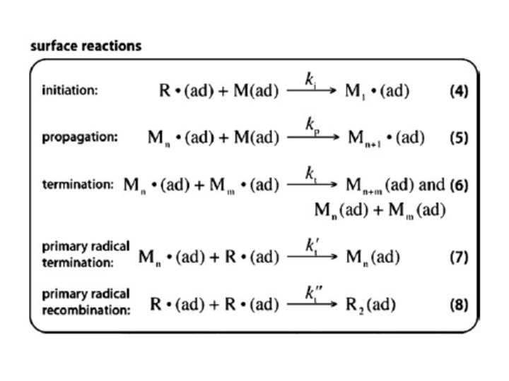
Rate limiting step i. CVD Filament temperature strongly influences deposition rate. At low filament temperatures, the radical formation from the initiator is the rate-limiting step. At higher filament temperatures, there is a weaker dependence between decomposition rate and filament temperature, suggesting that mass transport of the radical species to the surface becomes the rate-limiting mechanism.

Parylene CVD

Jia et al. : Laboratory pentacene and parylene evaporation systems

Parylene CVD: rate up when cooled

Rate limiting step This apparent negative activation energy is the signature that surface adsorption of a reactive species is the rate-limiting step. In the adsorption-limited regime, increased substrate temperature reduces adsorption onto the surface, leading to lower deposition rates, but often thickness uniformity is improved.
, is defined as the probability of a precursor")
Sticking coefficient Reactive sticking coefficient (g), is defined as the probability of a precursor species adsorbing/reacting each time it strikes the surface. As g increases, species increasingly stick to the surface on impact, leading to a faster deposition at the trench opening and poor step coverage. Conversely, low values of g lead to multiple collisionsbefore sticking, allowing for deposition deep inside high aspect ratio features.

Parylene step coverage: excellent Monomer first physisorbs and chemisorbs only after overcoming an energy barrier. For the chemisorbed monomer, sticking coefficient was 2. 0*10 -5 at 60 o. C and increased to 1. 4*10 -3 at -60 o. C.
 (parylene) i. CVD poly(tetrafluoro")
Step coverage 300 nm deep trench conformally coated with poly(p-xylylene) (parylene) i. CVD poly(tetrafluoro ethylene) (PTFE)
 (PEDOT) with")
Electrically conducting polymers Electrochemical synthetic methods produce films of poly(3, 4 ethylenedioxythiophene) (PEDOT) with conductivities as high as 300 S cm-1 but only with conducting substrates. Wet-chemical oxidative polymerization from solutions containing oxidants like Fe. Cl 3 or iron(III) p-toluenesulfonate results in PEDOT films with similar conductivities. Soluble solid-state dopant poly(styrenesulfonate) PEDOT: PSS enables spin-casting of composite films.
 is the most commonly used monomer.")
CVD of PEDOT • 3, 4 -ethylenedioxythiophene (EDOT) is the most commonly used monomer. • PEDOT has also been reported using Fe. Cl 3 as oxidant. Rather than being delivered through the vapor phase, the Fe. Cl 3, which is a low volatility solid under ambient conditions, was pre-applied to the substrate by a dip or a microgravure roll coating method. The monomer was subsequently delivered through the vapor phase.
 • Both the oxidant and commercially available monomers are delivered")
o. CVD (oxidative CVD) • Both the oxidant and commercially available monomers are delivered directly to the substrate in the vacuum chamber in a single step through the vapor phase. [ • PEDOT films (up to 1000 S cm-1) with thicknesses more than 200 nm are formed in 30 min. • o. CVD of PEDOT has been demonstrated to be compatible with glass, silicon, plastic and paper substrates.

o. CVD reactor
) A step")
Stimuli responsive films • PECVD has been used to polymerize PNIPAAm (poly(N-isopropylacrylamide)) A step change from hydrophilic to hydrophobic is induced by conformal changes in the conformation of the polymeric structure as the temperature is raised above the LCST transition point.

Surface activation • Chemical activation of the substrates. • Organic or inorganic substrates can be chemically activated prior to polymerization by creating reactive free-radical species on the surface. • Near-UV irradiation (>300 nm) and photoinitiator benzophenone creates reactive sites directly on poly(ethylene) and poly(styrene) substrates
 • Organic substrates can be chemically activated using a plasma glow")
Surface activation (2) • Organic substrates can be chemically activated using a plasma glow discharge. • This activation generates free-radical species on the substrate that can initiate polymerization when contacted with gas-phase polymer precursors. • Alternatively, inorganic substrates can be chemically activated using a piranha solution or oxygen plasma pretreatment to create a high density of surface hydroxyl groups.
 films with thicknesses as low as 1. 5 nm have been")
Thickness • poly(imide) films with thicknesses as low as 1. 5 nm have been obtained • Poly(N-carbobenzyloxy-L-lysine) films ranging from 4– 120 nm were achieved • Uniform, 3 µm thick poly(methyl methacrylate) (PMMA) films have been synthesized • highly crosslinked 30 mm poly(imide) VDP layers have been formed, exhibiting high Young’s moduli and tensile strength, as well as being insoluble in sulfuric acid
 14 22 Active channel material in polymer electronics")
(C H ) 14 22 Active channel material in polymer electronics

Evaporator for pentacene

Knudsen cell for pentacene Knudsen Cell is an isothermal enclosure with a small orifice. Vapor emerges in a thermal equilibrium process.

Pentacene TFT process

Flexible TFT: parylene passivation, silicon substrate detachment Feili et al: J. Micromech. Microeng. 16 (2006) 1555– 1561

Evaporation good for lift-off Goettling et al: JOURNAL OF DISPLAY TECHNOLOGY, VOL. 4, NO. 3, SEPTEMBER 2008

Sputtering of polymers Need RF-sputter deposition rates ~0. 6 nm/s Hynek Biederman: Organic films prepared by polymer sputtering, JVST A 2000

Sputtering polymers Organic films that can be best described as fluorocarbon plasma polymers were usually prepared in the so called selfsputtering mode. In this case argon was used to initiate the discharge that continued to be maintained by the volatile fragments when the argon supply was shut off. RF sputtering of PTFE was also performed in argon. Because sputtered fluorocarbon films were found deficient in fluorine, RF sputtering of PTFE in a CF 4– Ar mixture was used and shown to give stoichiometric films.

Film structure • These F-rich fluorocarbon plasma polymer films were stable at 450 °C for 4 h. • Even after 24 h at 450 °C no crystalline structures were observed by x-ray diffraction, i. e. , the films appeared to be amorphous.
")
Film structure (2)
 1102– 1113")
Film adhesion Bodas & Gangal: J. Micromech. Microeng. 15 (2005) 1102– 1113
 1102–")
Sputtered Teflon as etch mask Bodas & Gangal: J. Micromech. Microeng. 15 (2005) 1102– 1113
- Slides: 39