POLYMER PROCESSING MACHINERY MODULE I THE MIXING MACHINERY


 or")


 and distributive (extensive) mixing. •")


 •")


 • FCM is a counter-rotating, non-intermeshing twin-rotor mixer. • Its")


 consists of a pneumatically operated")


- Slides: 51
POLYMER PROCESSING & MACHINERY
MODULE I -THE MIXING MACHINERY 1. 1. 0 To comprehend the mixing machinery • 1. 1. 1. Classify the mixing equipment's • 1. 1. 2. Explain the working principle, various parts and accessories, safety devices and important uses of Open Two Roll Mixing Mill. • 1. 1. 3. Explain the working principle, various parts and accessories of Banbury and Intermix. • 1. 1. 4. Describe fill factor, mixing sequences, distributive mixing, dispersive mixing and upside down mixing. • 1. 1. 5. Compare and contrast between Open two roll mill and internal mixers. • 1. 1. 6. Distinguish between Banbury and intermix. • 1. 1. 7. Explain the temperature and pressure control systems of mixing equipment's. • 1. 1. 8. Discuss various continuous mixing equipment's like Double R mixer, Farrel continuous mixer, Transfer mixer and MVX mixer.
The major steps of rubber product manufacture can be summarized into three 1. Compounding 2. Shaping/Forming 3. Vulcanization
Mixing • The first step in the manufacture of various rubber products from dry forms of rubber is known as compounding of rubber. • Here rubber is masticated on a mixing machine followed by the incorporation of the required ingredients into the properly masticated rubber. • Mixing is defined as the process which reduce the composition nonuniformity of a mixture of two or more components. • The mixing of ingredients into the rubber is highly complex and involves both shear and elongational flow depending on the viscosity of the rubber system, thus making the fluid elements to be strained under applied stress. • The equipment’s used for mixing or compounding may be an open 2 -roll mixing mill, a kneader or an internal mixer.
Principle of Mixing • Due to the partly elastic nature and very high viscosity of rubber, power intensive machinery like mixing mills or internal mixers is necessary to achieve the mixing of additives into the polymer. • The ingredients are in form of liquids, solid powders or solid agglomerates. • The mixing of solid ingredients into the solid polymer occurs in phases
• During subdivision large lumps or agglomerates are broken down into smaller aggregates suitable for incorporation into the rubber. For instance carbon black pellets which have dimension of the order of 250 -2000 µm get broken down into aggregates with dimensions of the order of 100 µm. Then these aggregates are absorbed or incorporated into the rubber to form a coherent mass.
• During mixing, shearing of the rubber generates shearing stress in rubber mass which imposes in turn shear stress on these aggregates and breaks these into their ultimate fine size which in case of carbon blacks is of the order of about 1µm in size. This phase is also known as intensive mixing. • Distribution or homogenization in micromolecular level or extensive mixing is “the moving of the agglomerates / particles from one point to another, without changing the shape of the particle to increase the randomness of the mixture”. The ingredients incorporation is a very slow process.
• Even after all ingredient is incorporated, dispersion/distribution of the ingredient is not complete. Good distribution is comparatively easy to achieve by paying proper attention to cutting and folding operations on a mixing mill or by just prolonging the mixing cycle in an internal mixer • Dispersion however is dependent on the shear stresses generated within the polymer and hence good dispersion may not be achieved by prolonged mixing. Careful consideration is necessary not only as regards the time of the mixing cycle but also for the order of addition of ingredients to the rubber. • Viscosity break down occurs during mixing and is essential for smooth processing of the stock.
Mixing Mill
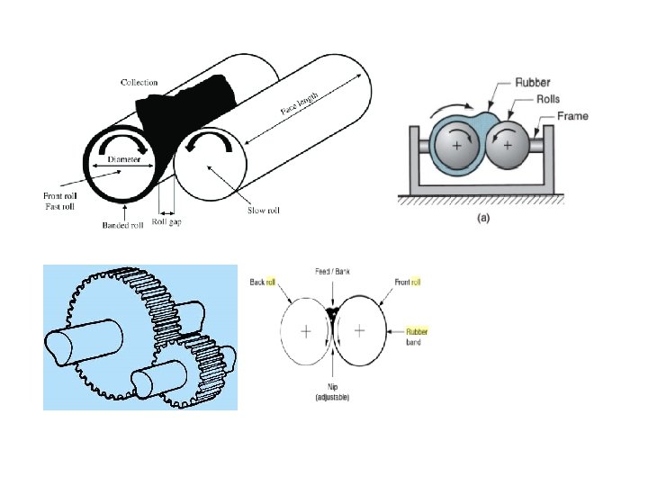
Working of a two roll mill • Consists of two adjacent smooth , hardened steel rolls set horizontally • They rotate in opposite directions, produces friction or grinding action between them. • Ratio between the operating speed of the front roll and back roll is referred to as friction ratio • Usually, the friction ratio is kept around 1: 1. 25 to 1: 1. 4 for the front to back roll. • Back roll moves faster than the front roll; a common friction ratio is 1: 1. 25 • The rolls of the mixing mill are connected to the drive motor through appropriate gears to adjust speed. • Mixing was achieved by the shearing action induced in the space between the rolls which is adjustable • During the mixing operation, cutting and blending is carried out in order to obtain a thorough and uniform dispersion of the ingredients in the polymer mix.
Parts of a two roll mill
Parts of a two roll mill 1. Rolls: • These are chilled cast iron rolls, cylindrical, exactly identical in shape, horizontally drilled to facilitate the circulation of hot/cool water and highly polished. These rolls are set in heavy frames. • Generally rolls are rotated in opposite direction with uneven speed back roll is faster than the front roll. 2. Motor: • Rolls are rotated by 3 phase induction motor of high torque. 3. Reduction gear unit: • The driving force is transmitted from a motor to rolls through a reduction gear which reduces the high speed of motor to maximize the torque and to reduce the surface speed of rolls.
4. Roll end gear: • The mixing mill rolls are connected endwise with two small gear wheels called the roll end gears. • These gears usually differ in their size and number of teeth so as to give differential speed to increase the friction and shearing force between the rolls. This friction and shearing force causes the breakdown of large polymer chains and there by viscosity of rubber gets reduced and this process is called “Mastication”. • Compounding ingredients are added to the masticated rubber which is soft and tacky. The number of teeth of the roll end gears determines the surface speed of two rolls. Friction ratio is generally 1: 1. 25. • Front roll is rotated by the power supplied from the back roll through roll end gears. Back roll is the driving roll.
5. Nip adjusting screws • The gap between the rolls is termed as Nip and this can be altered by the two square threaded screws fitted in the two ends of the front roll called Nip adjusting screws. 6. Vernier disc: • Two vernier discs are fitted at the end of the nip adjusting screws for the required uniform nip adjustment. 0 ne vernier disc is placed at the right end of the roll and the other one at the left end. Each should rotate in the same direction with same division to avoid tapering. 7. Safety Bar: • Safety bar is used for the emergency stoppage of the mixing mill. Mills are generally fitted with safety bar placed around and parallel to the mill rolls. It acts as a circuit breaker in the event of emergency.
8. Mill pan: • It is a rectangular shallow tray placed under the rolls for collecting the ingredients falling from the nip. 9. Oil pan: • It is a glass container having a lead tube which spills lubricating oil to the bearing. The rate of flow can be controlled by adjusting the nut. 10. Bed: • All the above parts are fixed on the bed of mixing mill. 11. Water cooling system: • Water is circulated through the cored or peripherally drilled holes of the rollers to reduce the heat on the rolls while running. MILL ACCESSORIES • Cutting knives, nip adjusting levers, dust collectors, fitted knives, roll attachments etc
Advantages and Disadvantages of two roll mill Advantages Disadvantages • Less capital investement • Occupies less space • Residence time control • Melt temperature control (cooling system more efficient) • versatile , can accomodate multiple mix types • Open , chances of contamination • Operator dependency on mix quality • Limited mix volume • Batch to batch variation • Larger mixing time
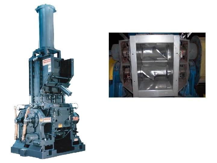
INTERNAL MIXER Ø An internal mixer is made up of two counter-rotating horizontal rotors with wings or protrusions enclosed in a closed chamber into which the rubber, and then the additives according to some pre-determined sequence, are dropped and sealed by a ram. Ø After mixing, the compound is dropped through the floor of the mixer for moulding and vulcanization. Ø Internal mixers are designed to produce both intensive (dispersive) and extensive (distributive) mixing. ü Intensive mixing occurs in the narrow gap between the rotor tip and mixing chamber. ü Extensive mixing takes place within the rotors
INTERNAL MIXER • Mixing chamber is the heart of the internal mixer. • Consists of a completely enclosed mixing chamber (horizontally in the form of figure eight) in which opposing spiral shaped rotors turning at same speed (intermeshing design) or at different speeds ( tangential design) to keep the material circulating. • Gap between the rotor tips and the chamber wall produces intensive shearing of the mixture. • A hopper allows for loading ingredients, and an air-operated ram in the feeding neck confines the batch within the mixing chamber.
INTERNAL MIXER • All the working parts of a Banbury are fully enclosed ensuring safe clean and healthy working condition for the operator. • A discharge door allows for quick and efficient unloading of the mixture at the end of the mixing cycle. • The mixing chamber, rotors, and discharge door are all temperature controlled with steam and/or water. • The rotors are drawn by a powerful electric motor and the mixing pressure is generated from a ram and the rubber is sheared between the rotors and the mixing chamber. • The rotors can be designed as either two or four wing types, four wing rotor provides faster mixing cycle.
Classifications of Internal Mixer Banbury mixer Internal Mixer Intermix The major difference between the two machines is due to the rotor and mixing chamber design.
BANBURY MIXER
• Banbury mixer developed by Fernley H. Banbury • Rotors in a tangential mixer have a major and minor diameter. • Each rotor turns independently (with friction ratio) in a cavity referred to as a "side. " • The tangential mixer develops high shear mixing predominately between the rotor tip and side wall of the mixing chamber. • It is in this area where the mixing material is forced through the tight clearance between the rotor wings and chamber wall, where dispersive mixing and polymer breakdown occur. • Here transferring of material around the mixing chamber occurs from one rotor to the other to give mix distribution. • Banbury mixers permits 20% mixing between rotors.
INTERMIX
• The design of the Intermix was contracted to Francis Shaw and Company of Manchester, who eventually acquired and patented the design. • Material was transferred along its length and in the opposite direction to the other rotor i. e. transferring from rotor to rotor occurs due to the interlocking nature of the rotors. • Intermeshing rotors are rolling with same speed and the mixing effect is achieved as in tangential system but with this system mixing takes place also in the nip between the rotors. • The major diameter of one rotor interacts with the minor diameter of the opposing rotor, and this dictates that the rotors be run at even speed (no friction ratio). • Intermix permits 80% mixing between rotors.
Parts of an internal mixer • Feed Hopper consists of a hopper opening and door followed by a chute for loading the materials into the mixing chamber ; opening provided at the operator side of the machine and can be opened or closed using a lid • Floating weight (Ram or Plunger) can be lowered or raised allowing the raw materials to be added into also forces the added materials into the mixing chamber. It is also named as ram (Banbury) or a Plunger (Intermix). It is the air pressure (10 to 120 psi) applied by the bottom of the ram/plunger that can affect the mixing time or shear on the compound, affecting distributive / dispersive mixing.
Parts of an internal mixer • Mixing Chamber The mixing chamber houses the rotors inside it, receives the ingredients of the mix through hopper chute. It has an opening on the top side, which is closed by the floating weight and at the bottom, has an opening for the discharge of the mixed compound which is sealed by the discharge door top in its closed position. Temperature control of the mixing chamber is accomplished with steam or circulating water
• Rotors rotating toward each other at the same speed (intermeshing design) or at different speeds (tangential design). The rotors are designed to interact with each other via the rotor blades, called wings. Short wings and long wings are used in combination on each rotor. Rotors are arranged in the mixer such that the long wing of one rotor interacts with the short wing of the other rotor. Edge of the blade is called the wing tip, which forms the shearing gap between the rotor blade and the chamber wall. Rotors are temperature controlled with steam and/or water, which flows through the center of each shaft.
• Discharge door Designed to provide quick and efficient dumping of the mixture. The door top must be hard-surfaced to withstand the mixing environment; most discharge doors are provided with passages for heating or cooling media; the door is usually cooled to prevent the mixture from sticking. Two types are available: drop door and sliding door.
• Motor and Gearbox Internal mixers are driven by huge prime movers through appropriate reduction gears. • Temperature Control Unit Energy spent in mixing is manifested in the form of heat the batch acquires during the mix cycle. Heat generated makes the stock to plasticise and excessive plasticisation is not advisable since it affects the compound properties. Problem can be resolved by using water circulation through the chamber.
Dispersive & Distributive mixing
• Rubber compounding typically requires both dispersive (intensive) and distributive (extensive) mixing. • Dispersive mixing involves generating high stresses in the melt to reduce significantly the size of any dispersed particles whereas distributive mixing involves stretching, dividing and reorienting the flow of the polymer melt compound in order to eliminate local variations in material distribution and produce a more homogeneous mixture. For Banbury mixers (tangential rotors), dispersive mixing is accomplished in high shear tapering nip regions between rotor tips and the mixer wall. • Distributive mixing occurs by transfer of material from one rotor to another and around the mixing chamber. Intermeshing rotors provide dispersive mixing in the nip between the rotors and facilitate transfer of material from rotor to rotor.
Internal Mixing Methods/ Procedures Depending on the sequence of addition of ingredients, a variety of mixing methods are available. The three identified mixing methods using an internal mixer as: – Conventional Method – Rapid oil addition method ( Early oil addition method) – Upside down mix method
Internal Mixing Methods/ Procedures Conventional Method • Consists of adding the elastomer first followed by the dry ingredients and finally the liquid ingredients, once the dry materials are well dispersed in the elastomer. • This method can achieve a homogeneous dispersion of all ingredients, including fillers of very small particle size. • However the mixing time required is usually long because of the difficulty in incorporating liquid ingredients once the dry materials have been dispersed in the rubber matrix. • Significant amount of slippage and loss of efficiency occurs inside the chamber till the time the oil is incorporated.
Internal Mixing Methods/ Procedures Rapid oil addition method ( Early oil addition method) • This method involves adding the elastomer first and the dry ingredients as soon afterward as possible. • After 1 to 2 min, all liquid ingredients are added together. • In this method dispersion is improved if the addition of ingredients are delayed slightly, however this will extend the mixing cycles. • This method is used for compounds containing large volume of liquid plasticizers
Internal Mixing Methods/ Procedures Upside down mix method • This method is the fastest and simplest way of mixing. • It is especially efficient and effective for those compounds containing a large volume of liquid plasticizers and large particle size of fillers. • This method involves adding all ingredients into the mixer before lowering the ram and beginning of mixing. • All the dry ingredients are added to the mixer first, then the liquids, and finally the elastomer on the top.
Temperature and pressure control systems of mixing equipment’s • The temperature control of the mixing equipment’s is the most important control parameter for constant mixing quality. • Large amount of energy are consumed during the mixing process and this give rise to large temperature rises in the rubber batch. • Therefore sufficient cooling channels must be provided to dissipate the generated heat produced during the mixing process. • The temperature of the mixer exerts a strong influence on the characteristics of mixing.
Temperature and pressure control systems of mixing equipment’s First batch effect • The variations in mixer temperature gave rise to ‘First batch effect’ where the physical properties of the batches produced immediately after startup are substantially different from those subsequently produced when the mixture has achieved its operating temperature when mixing time or batch temperature dump criteria are used. • During start up heat transfer from the batch is extremely efficient, due to the considerable mass of metal in the rotor and chamber acting as heat sink, delaying rise in temperature. • The first batch effect and subsequent variations in the properties of mixed batches are reduced by controlling the temperature of the water circulated through the chambers, rotors and drop door for cooling
• Ram pressure, applied either by hydraulic, pneumatic or mechanical means, can be varied to suit the needs of the mixing department. • High ram pressures decreases the voids within the mixtures and increases shear stress by increasing the contact forces between the ingredients and the rotor surface. • This helps greatly in breakdown of agglomerates thus allowing higher loadings of fillers in the mix.
Fill factor • Fill factor is an indication of the working volume of the mixer. Chamber volume is used to specify internal mixing capacity (in litres or cubic inches); empty volume is measured with the rotors installed. • The working volume is the space occupied by the mixture (function of batch weight, specific gravity). • Ratio of working to empty volume gives the fill factor. • The fill factor most suitable for rubbers is about 70 -75 % which was determined through experience.
Fill factor • Under filling of the mixing chamber is essential for efficient mixing and fill factors in the range 0. 65 -0. 85 are generally used, depending on mix type. • Within the range 0. 65 -0. 85, it is possible to retain the batch in regions where active mixing occurs. • Very low fill factors are uneconomic and excessive high fill factor result in material remaining on the throat of the mixer and not taking part in the mixing
Advantages and Disadvantages of Internal Mixers Advantages Disadvantages Safer, cleaner, more healthy Rapid working conditions temperature rise necessitates separate step for curative addition Greater saving in factory floor Time consuming to clean space, power, labour Shorter mixing time ( 5 -6 min) High capital cost associated with take away system and feed system Better and more uniformity, Smaller or bigger batches cannot reproducibility and uniform quality of mix Minimum dependence on be mixed
Farrel Continuous Mixer (FCM) • FCM is a counter-rotating, non-intermeshing twin-rotor mixer. • Its distinctive feature is that the clearance between screw flights and the barrel is much less than in twin screw extruder. • This leads to increased shearing between screw flights tips and the machine barrel.
• Consists of a counter rotating twin-screw extruder having overall length to diameter ratio (L/D) of about 5. • The feed zone is equipped with a hopper for metering a preblend of ingredients. • Followed by a mixing zone where the sections of the screws mimic Banbury rotors. • The continuous mixer carries out the unit operations of mixing - incorporation, distribution, dispersion and viscosity reduction in much the same fashion as an internal mixer.
Working • Ingredients are fed into the deep channelled screws through the feed section and is continuously transported to the rotors in the mixing chamber. • Mixing chamber contains rotors having flights that extend down the length of each rotor in a roughly helical manner. • Unmelted ingredients entering the mixing chamber are carried forward by the forward helix and back against the flow by the reverse helix resulting in an intense fluxing action that thoroughly mixes the ingredients.
Working • As the material is fluxed it is also forced to pass between the rotating tangential blades and the barrel wall generating shear. • Additional mixing is provided as kneading and rolling actions enhance lateral interchange of material between the two rotors. • Finally, the homogenous melt progresses down the rotor towards the discharge orifice gate which, unlike the discharge end/die in screw extruders, must be narrowed or widened to control throughput. • FCM is used for making master batches with high filler loadings
Farrel Mixing Venting Extruder / MVX Mixer • This machine is a combination of internal mixer and extruder, i. e. in a basic design a mixing chamber with rotors is mounted above an extruder. • The screw speed together with the rotor speed determines the mixing degree
• In MVX mixer, the feeding device (A) consists of a pneumatically operated ram which forces raw materials into the mixing chamber. • The mixing chamber (B) contains two counter rotating, delta-shaped rotors. • A variable speed drive operates the rotors at a 1. 1: 1 speed differential. • Compound being mixed passes the length of the rotors and is driven through the exit port into the extruder. • Two provisions for venting trapped air, moisture or other volatiles are incorporated into the design. • The mixing chamber is vented at atmospheric pressure (C) and the extruder equipped for vacuum venting (E). • The extruder section (D) can be of variable length, depending on the application. MVX has been shown to be capable of single – pass mixing of high reinforced compounds without the generation of excessive rubber temperatures suggesting that it is more energy efficient than FCM.
Transfermix
• Transfermix is a rubber extruder with specialized screw designs designed for improving mixing capacity. • The transfermix has helical channels machined in both the screw and the barrel. • The depth of the channel varies alternately along the length of the barrel. • Thus the melt is transferred from the channel in the screw to the channel in the barrel wall as it is transported down the barrel. • Each transfer from one channel to another, the material passes over the clearance between the two flights, where the shear stresses are maximum.