
Polarized Positrons for Future Linear Colliders Sabine Riemann
Polarized Positrons for Future Linear Colliders Sabine Riemann, DESY Zeuthen Thanks to the members of the ILC/CLIC Positron Source Group High precision measurements of luminosity at future linear colliders and polarization of lepton beams October 3 -5, 2010 FCAL & Polarization, S. Riemann, Polarized e+ for TAU 2010 Argonne, Sep 18 th, 2007 FLC Positron Polarization
Outline • • • Why polarized positrons? Generation of polarized positrons The ILC Positron Source Polarized positrons for CLIC Polarimetry at the positron source Summary FCAL & Polarization, TAU 2010 S. Riemann, Polarized e+ for FLC 2
Why polarized positrons ? Goal of a Future Linear Collider Observe, determine and precisely reveal the structure of the underlying physics model Needed: – High energy – High luminosity – Polarization knowledge of initial state – High precision Experimental flexibility be prepared for the unexpected The electron beam of a future LC will be polarized. Physics reasons to have a polarized positron beam are summarized in a review article; see Moortgat-Pick et al. , Phys. Rept. 460(2008)131 But positron polarization is not the Baseline Design of ILC or CLIC FCAL & Polarization, TAU 2010 S. Riemann, Polarized e+ for FLC 3
Questions (1) P(e+) is useful – but is it indispensable for a future linear collider? – Up to now we have not yet obtained new signatures that cannot be studied without positron polarization – Signals beyond the Standard Model found at the LHC can be interpreted with substantially higher precision if positron polarization is available distinction of new physics models – Z factory: Giga. Z 10^9 Z bosons • extreme precision for weak mixing angle, dsin 2 q. W ≈ 1 E-5 information about nature of symmetry breaking Giga. Z is impossible without e+ polarization FCAL & Polarization, TAU 2010 S. Riemann, Polarized e+ for FLC 4
Questions (2) What is the minimum P(e+) needed for physics? – Desired: ≥ 60% – Should not be below ~30% (t. b. c. ) – Flexible choice of polarization (+-, -+, --, ++), + transversly polarized beams Polarized e+ as upgrade option? ? – The undulator based source provides polarized e+ from the beginning (~30% ±) should be used for physics, not destroyed • if necessary (LHC results!), e+ positron polarization should be available from the beginning LC Design may not prevent a polarized positron beam FCAL & Polarization, TAU 2010 S. Riemann, Polarized e+ for FLC 5
Generation of polarized positrons FCAL & Polarization, TAU 2010 S. Riemann, Polarized e+ for FLC 6
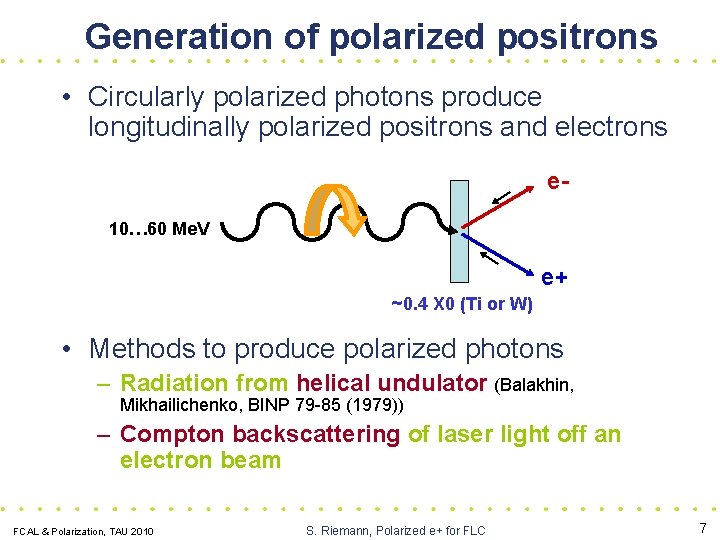
Generation of polarized positrons • Circularly polarized photons produce longitudinally polarized positrons and electrons e 10… 60 Me. V e+ ~0. 4 X 0 (Ti or W) • Methods to produce polarized photons – Radiation from helical undulator (Balakhin, Mikhailichenko, BINP 79 -85 (1979)) – Compton backscattering of laser light off an electron beam FCAL & Polarization, TAU 2010 S. Riemann, Polarized e+ for FLC 7
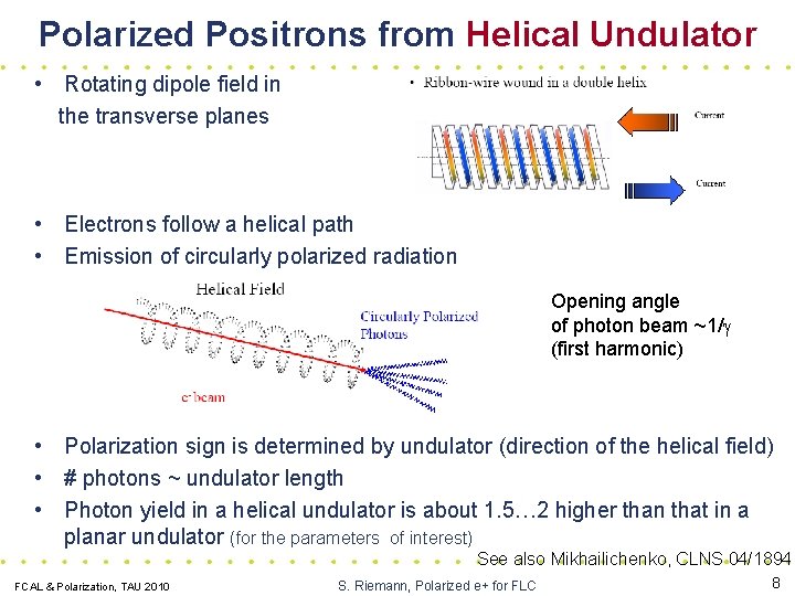
Polarized Positrons from Helical Undulator • Rotating dipole field in the transverse planes • Electrons follow a helical path • Emission of circularly polarized radiation Opening angle of photon beam ~1/g (first harmonic) • Polarization sign is determined by undulator (direction of the helical field) • # photons ~ undulator length • Photon yield in a helical undulator is about 1. 5… 2 higher than that in a planar undulator (for the parameters of interest) See also Mikhailichenko, CLNS 04/1894 FCAL & Polarization, TAU 2010 S. Riemann, Polarized e+ for FLC 8
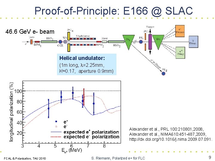
Proof-of-Principle: E 166 @ SLAC 46. 6 Ge. V e- beam Helical undulator: (1 m long, l=2. 25 mm, K≈0. 17, aperture 0. 9 mm) Alexander et al. , PRL 100: 210801, 2008, Alexander et al. , NIMA 610: 451 -487, 2009, http: //dx. doi. org/10. 1016/j. nima. 2009. 07. 091. FCAL & Polarization, TAU 2010 S. Riemann, Polarized e+ for FLC 9
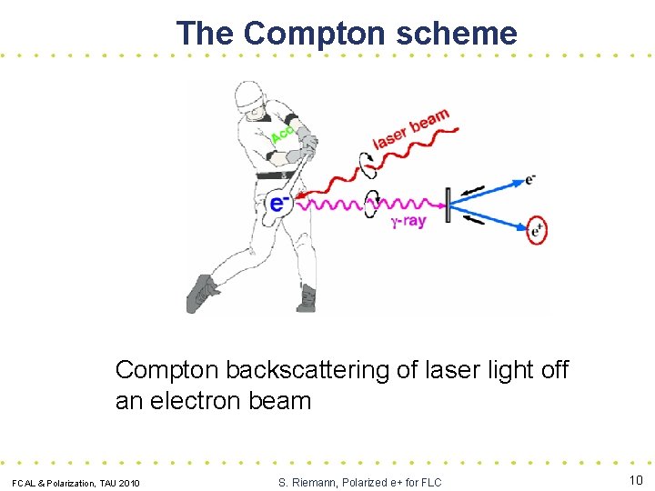
The Compton scheme Compton backscattering of laser light off an electron beam FCAL & Polarization, TAU 2010 S. Riemann, Polarized e+ for FLC 10
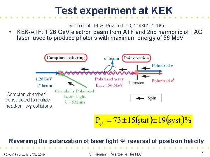
Test experiment at KEK Omori et al. , Phys. Rev. Lett. 96, 114801 (2006) • KEK-ATF: 1. 28 Ge. V electron beam from ATF and 2 nd harmonic of TAG laser used to produce photons with maximum energy of 56 Me. V ‘Compton chamber’ constructed to realize head-on e-g collisions Reversing the polarization of laser light reversal of positron helicity FCAL & Polarization, TAU 2010 S. Riemann, Polarized e+ for FLC 11
Polarized e+ for Future LC FCAL & Polarization, TAU 2010 S. Riemann, Polarized e+ for FLC 12
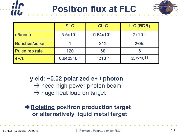
Positron flux at FLC SLC CLIC ILC (RDR) 3. 5 x 10¹⁰ 0. 64 x 1010 2 x 10¹⁰ Bunches/pulse 1 312 2685 Pulse rep rate 120 50 5 0. 042 x 1014 1 x 10¹⁴ 2. 7 x 10¹⁴ e/bunch e+/s yield: ~0. 02 polarized e+ / photon need high power photon beam huge heat load on target Rotating positron production target or alternatively liquid metal target FCAL & Polarization, TAU 2010 S. Riemann, Polarized e+ for FLC 13
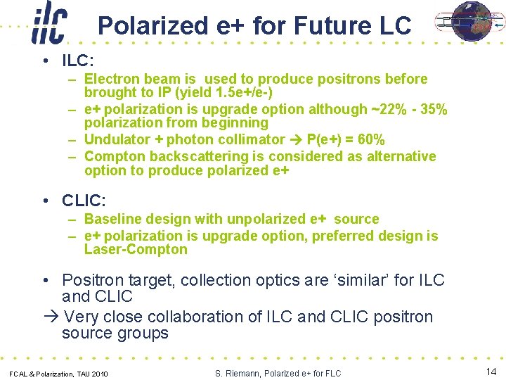
Polarized e+ for Future LC • ILC: – Electron beam is used to produce positrons before brought to IP (yield 1. 5 e+/e-) – e+ polarization is upgrade option although ~22% - 35% polarization from beginning – Undulator + photon collimator P(e+) = 60% – Compton backscattering is considered as alternative option to produce polarized e+ • CLIC: – Baseline design with unpolarized e+ source – e+ polarization is upgrade option, preferred design is Laser-Compton • Positron target, collection optics are ‘similar’ for ILC and CLIC Very close collaboration of ILC and CLIC positron source groups FCAL & Polarization, TAU 2010 S. Riemann, Polarized e+ for FLC 14
Polarized Positrons for the ILC FCAL & Polarization, TAU 2010 S. Riemann, Polarized e+ for FLC 15
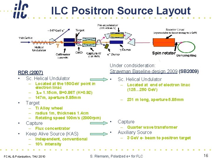
ILC Positron Source Layout Spin rotator Under condsideration: Strawman Baseline design 2009 (SB 2009) RDR (2007) • Sc. Helical Undulator – Located at the 150 Ge. V point in electron linac – l = 1. 15 cm, B=0. 86 T (K=0. 92) – 147 m, aperture 5. 85 mm • Capture – Flux concentrator • Keep Alive Source (KAS) – Independent, conventional – 10% intensity FCAL & Polarization, TAU 2010 Sc. Helical Undulator – Located at end of electron linac (125… 250 Ge. V) – 231 m long, aperture 5. 85 mm Target – Ti Alloy wheel – radius 1 m, thickness 1. 4 cm – Rotating speed 100 m/s (2000 rpm) • • • Capture – Quarter wave transformer • Auxiliary Source – 3 Ge. V e- beam to positron target S. Riemann, Polarized e+ for FLC 16
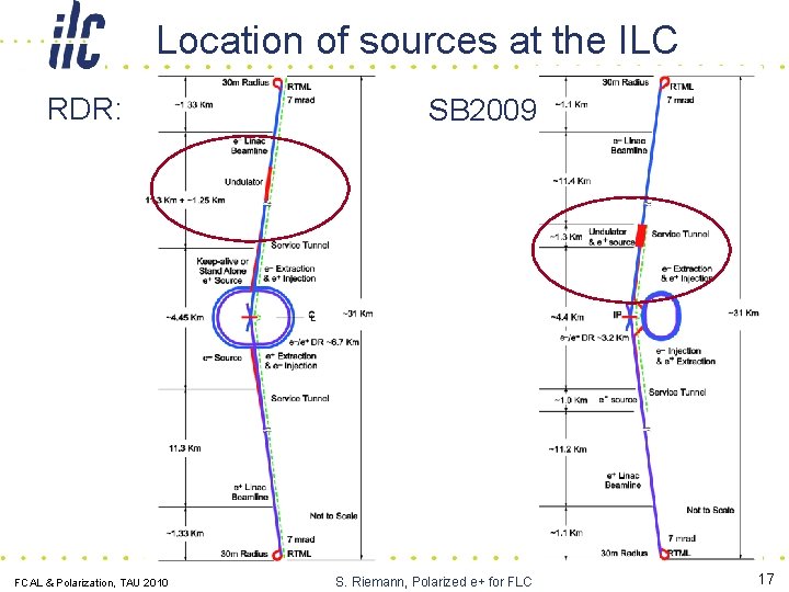
Location of sources at the ILC RDR: FCAL & Polarization, TAU 2010 SB 2009 S. Riemann, Polarized e+ for FLC 17
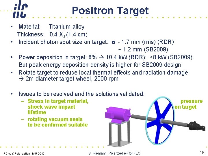
Positron Target • Material: Titanium alloy Thickness: 0. 4 X 0 (1. 4 cm) • Incident photon spot size on target: s ~ 1. 7 mm (rms) (RDR) ~ 1. 2 mm (SB 2009) • Power deposition in target: 8% 10. 4 k. W (RDR); <8 k. W (SB 2009) But peak energy deposition density is higher for SB 2009 design • Rotate target to reduce local thermal effects and radiation damage 2 m diameter target wheel, 2000 rpm • Issues to be resolved and the solutions validated: – Stress in target material, shock wave impact lifetime – rotating vacuum seals to be confirmed suitable FCAL & Polarization, TAU 2010 pressure on target S. Riemann, Polarized e+ for FLC 18
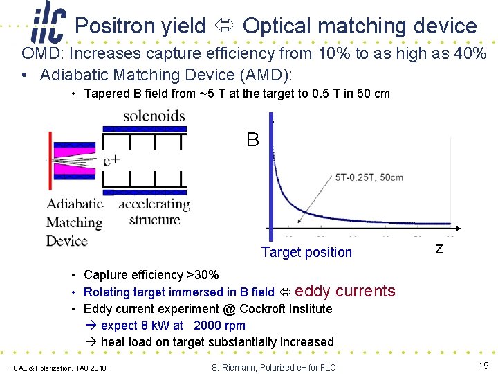
Positron yield Optical matching device OMD: Increases capture efficiency from 10% to as high as 40% • Adiabatic Matching Device (AMD): • Tapered B field from ~5 T at the target to 0. 5 T in 50 cm B Target position Z • Capture efficiency >30% • Rotating target immersed in B field eddy currents • Eddy current experiment @ Cockroft Institute expect 8 k. W at 2000 rpm heat load on target substantially increased FCAL & Polarization, TAU 2010 S. Riemann, Polarized e+ for FLC 19
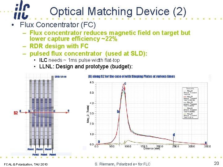
Optical Matching Device (2) • Flux Concentrator (FC) – Flux concentrator reduces magnetic field on target but lower capture efficiency ~22% – RDR design with FC – pulsed flux concentrator (used at SLD): • ILC needs ~ 1 ms pulse width flat-top • LLNL: Design and prototype (budget): Target position FCAL & Polarization, TAU 2010 S. Riemann, Polarized e+ for FLC 20
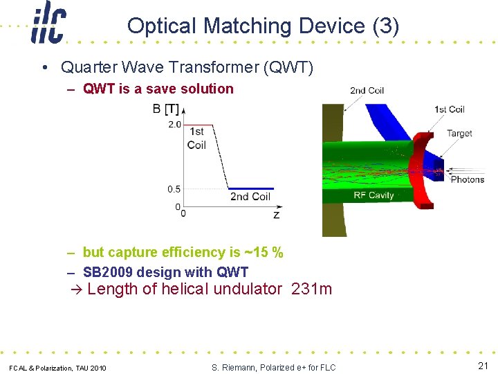
Optical Matching Device (3) • Quarter Wave Transformer (QWT) – QWT is a save solution – but capture efficiency is ~15 % – SB 2009 design with QWT Length of helical undulator 231 m FCAL & Polarization, TAU 2010 S. Riemann, Polarized e+ for FLC 21
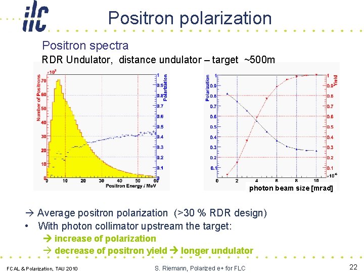
Positron polarization Positron spectra RDR Undulator, distance undulator – target ~500 m photon beam size [mrad] Average positron polarization (>30 % RDR design) • With photon collimator upstream the target: increase of polarization decrease of positron yield longer undulator FCAL & Polarization, TAU 2010 S. Riemann, Polarized e+ for FLC 22
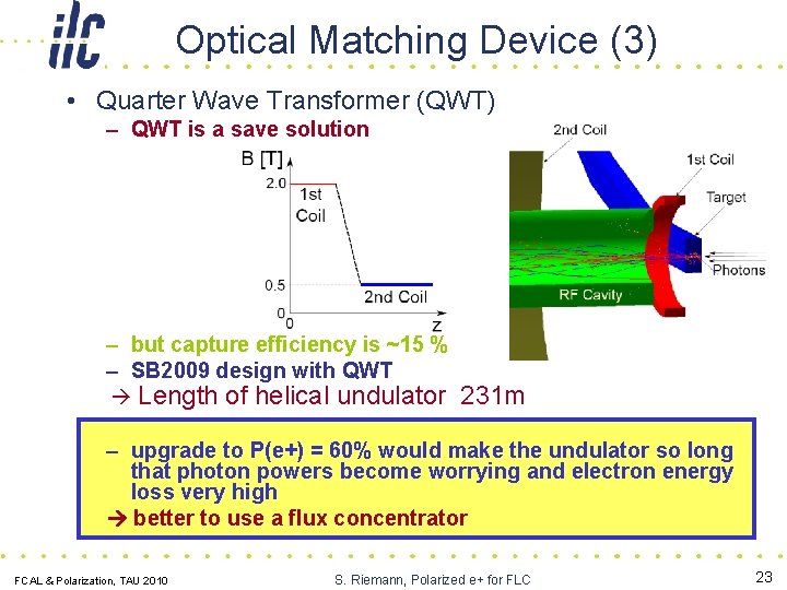
Optical Matching Device (3) • Quarter Wave Transformer (QWT) – QWT is a save solution – but capture efficiency is ~15 % – SB 2009 design with QWT Length of helical undulator 231 m – upgrade to P(e+) = 60% would make the undulator so long that photon powers become worrying and electron energy loss very high better to use a flux concentrator FCAL & Polarization, TAU 2010 S. Riemann, Polarized e+ for FLC 23
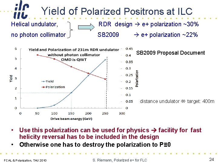
Yield of Polarized Positrons at ILC Helical undulator, RDR design e+ polarization ~30% no photon collimator SB 2009 e+ polarization ~22% SB 2009 Proposal Document distance undulator target: 400 m • Use this polarization can be used for physics facility for fast helicity reversal has to be included in the design • Otherwise one has to destroy the polarization to P≡ 0 FCAL & Polarization, TAU 2010 S. Riemann, Polarized e+ for FLC 24
Polarized Positrons for CLIC FCAL & Polarization, TAU 2010 S. Riemann, Polarized e+ for FLC 25
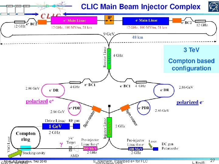
CLIC Polarized Positron Source • CLIC baseline design has an unpolarized e+ source, e+ polarization is upgrade option (3 Te. V) • Preferred: Compton scheme – e+ beam independent of the main beam linac – Polarized e+ source can be implemented at any time without modifications of the CLIC complex – But: Need high intensities for electron and laser beam; at present not available • Requested: 6. 7 x 10^9 e+/bunch at Pre. Damping. Ring stacking of e+ is necessary See also Rinolfi et al. , PAC 09, Vancouver, WE 6 RFP 065 • Proposed designs for electron-photon collisions: – Electron ring and optical laser cavity – ERL (Energy recovering linac) + laser cavities – Electron linac and CO 2 laser cavities no stacking • Undulator: possible, but integration into main linac is more complicated FCAL & Polarization, TAU 2010 S. Riemann, Polarized e+ for FLC 26
FCAL & Polarization, TAU 2010 S. Riemann, Polarized e+ for FLC 27
Positron Polarization Measurement • at the source • at the IP (see next Talk by Peter Schuler) FCAL & Polarization, TAU 2010 S. Riemann, Polarized e+ for FLC 28
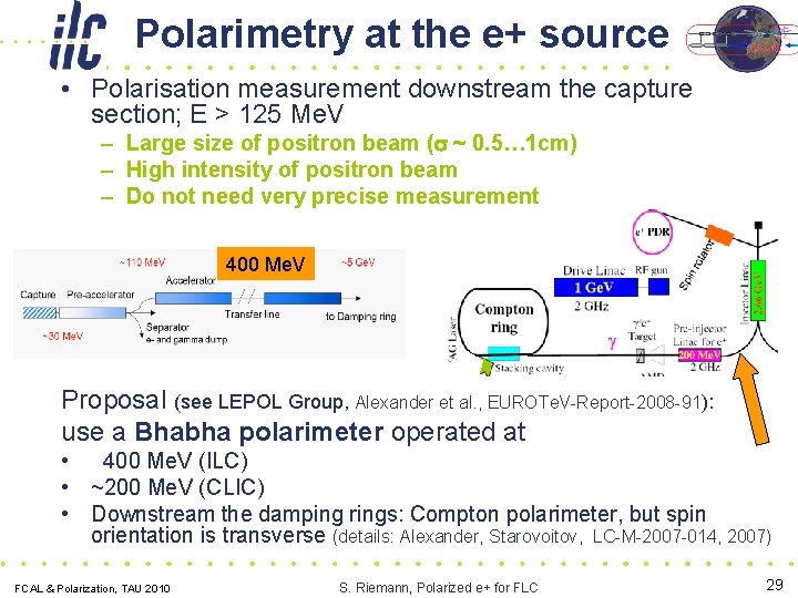
Polarimetry at the e+ source • Polarisation measurement downstream the capture section; E > 125 Me. V – Large size of positron beam (s ~ 0. 5… 1 cm) – High intensity of positron beam – Do not need very precise measurement 400 Me. V Proposal (see LEPOL Group, Alexander et al. , EUROTe. V-Report-2008 -91): use a Bhabha polarimeter operated at • 400 Me. V (ILC) • ~200 Me. V (CLIC) • Downstream the damping rings: Compton polarimeter, but spin orientation is transverse (details: Alexander, Starovoitov, LC-M-2007 -014, 2007) FCAL & Polarization, TAU 2010 S. Riemann, Polarized e+ for FLC 29
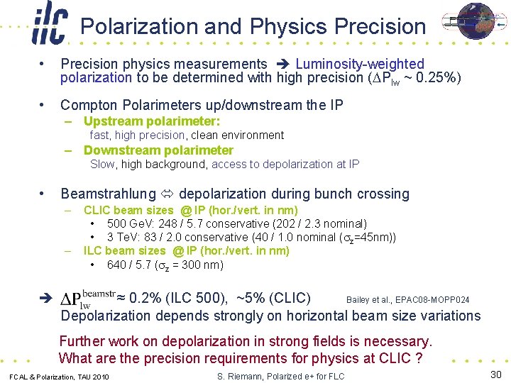
Polarization and Physics Precision • Precision physics measurements Luminosity-weighted polarization to be determined with high precision (DPlw ~ 0. 25%) • Compton Polarimeters up/downstream the IP – Upstream polarimeter: fast, high precision, clean environment – Downstream polarimeter Slow, high background, access to depolarization at IP • Beamstrahlung depolarization during bunch crossing – – CLIC beam sizes @ IP (hor. /vert. in nm) • 500 Ge. V: 248 / 5. 7 conservative (202 / 2. 3 nominal) • 3 Te. V: 83 / 2. 0 conservative (40 / 1. 0 nominal (sz=45 nm)) ILC beam sizes @ IP (hor. /vert. in nm) • 640 / 5. 7 (sz = 300 nm) ≈ 0. 2% (ILC 500), ~5% (CLIC) Bailey et al. , EPAC 08 -MOPP 024 Depolarization depends strongly on horizontal beam size variations Further work on depolarization in strong fields is necessary. What are the precision requirements for physics at CLIC ? FCAL & Polarization, TAU 2010 S. Riemann, Polarized e+ for FLC 30
Summary • Positron polarization is important and will be available from the beginning if the helical undulator is baseline design • Milestones: – ILC: Technical Design Report end 2012 – CLIC: CDR in 2011 • Still to do – – Demonstrate target reliability Demonstrate that the flux concentrator will work Realistic spin tracking from start to end Depolarization effects at IP • BMBF Joint Research Project ‘Spin Management’ FCAL & Polarization, TAU 2010 S. Riemann, Polarized e+ for FLC 31
Joint Research Project: Spin Management • Funded by BMBF (Federal Ministry of Education and Research in Germany) • Participants: – – Uni HH (Prof. G. Moortgat-Pick) Uni Bonn (Prof. W. Hillert) Uni Mainz (Prof. K. Aulenbacher) Collaborating groups at DESY (J. List (HH), S. Riemann (Zeuthen)) • Spin management (FLC related): – – – Precision polarization measurement at the IP Depolarization effects in strong fields e+ source modeling, spin rotation + fast helicity reversal Spin tracking Physics potential of the LC Collaboration Uni HH, DESY Bonn • simulations and measurements of spin rotation and spin transport through damping ring • Positron Production Target – – Simulation of radiation and thermal load Consequences for material aging shock waves: modeling (simulations) experimental tests currently under discussion FCAL & Polarization, TAU 2010 S. Riemann, Polarized e+ for FLC 32
Summary • Positron polarization is important and will be available from the beginning if the helical undulator is baseline design • Milestones: – ILC: Technical Design Report end 2012 – CLIC: CDR in 2011 • Still to do – – Demonstrate target reliability Demonstrate that the flux concentrator will work Realistic spin tracking from start to end Depolarization effects at IP • BMBF Joint Research Project ‘Spin Management’ • Still missing – for ILC and CLIC: – Realistic scenarios with polarization and consequences for physics precision important for physics potential of the LC machine/detector design – LHC signals beyond the SM Positron polarization needs more attention from machine and physics groups to be prepared for the unexpected 33 S. Riemann, Polarized e+ for FLC FCAL & Polarization, TAU 2010

Thank you! FCAL & Polarization, TAU 2010 S. Riemann, Polarized e+ for FLC 34
- Slides: 34