
Polarization Techniques for Interferometer Control Peter Beyersdorf National
Polarization Techniques for Interferometer Control Peter Beyersdorf National Astronomical Observatory of Japan LSC March 2002 Advanced Configurations LIGO-G 020024 -00 -Z
Outline • • Motivation Introduction to basic polarization techniques Some uses of these techniques Examples – Locking of a Ring Mode Cleaner – Generating multiple sidebands – Creating a “single sideband” • My plans to use these techniques with RSE – Getting a LO for SEC past the power recycling mirror – An RSE interferometer with only 4 degrees of freedom • Conclusion
Motivation for this talk Since the interferometers we work with have many constraints, having an extra degree of freedom (polarization) can greatly simplify the design. Despite this I’ve found that many gravity wave interferometer experts are not familiar with polarization techniques.
Motivation for this talk Since the interferometers we work with have many constraints, having an extra degree of freedom (polarization) can greatly simplify the design. Despite this I’ve found that many gravity wave interferometer experts are not familiar with polarization techniques.
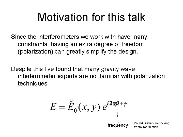
Motivation for this talk Since the interferometers we work with have many constraints, having an extra degree of freedom (polarization) can greatly simplify the design. Despite this I’ve found that many gravity wave interferometer experts are not familiar with polarization techniques. frequency Pound-Drever-Hall locking frontal modulation
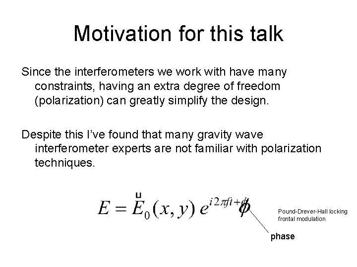
Motivation for this talk Since the interferometers we work with have many constraints, having an extra degree of freedom (polarization) can greatly simplify the design. Despite this I’ve found that many gravity wave interferometer experts are not familiar with polarization techniques. Pound-Drever-Hall locking frontal modulation phase
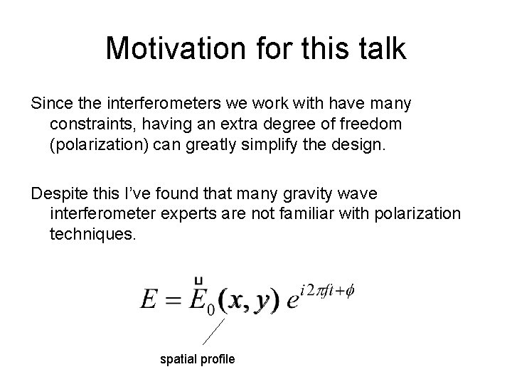
Motivation for this talk Since the interferometers we work with have many constraints, having an extra degree of freedom (polarization) can greatly simplify the design. Despite this I’ve found that many gravity wave interferometer experts are not familiar with polarization techniques. spatial profile
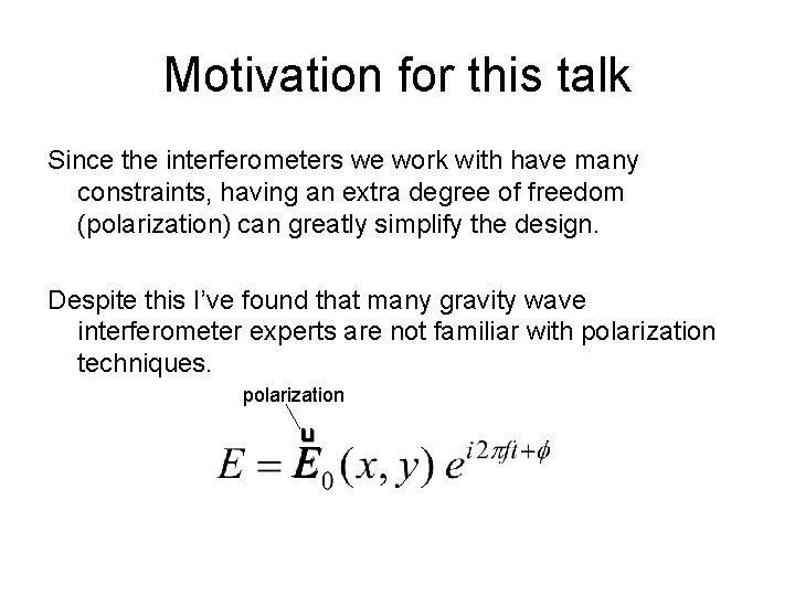
Motivation for this talk Since the interferometers we work with have many constraints, having an extra degree of freedom (polarization) can greatly simplify the design. Despite this I’ve found that many gravity wave interferometer experts are not familiar with polarization techniques. polarization
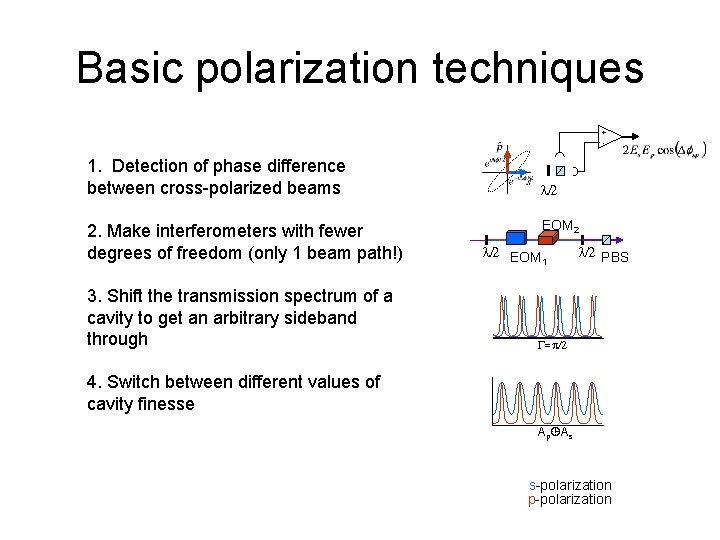
Basic polarization techniques + - 1. Detection of phase difference between cross-polarized beams 2. Make interferometers with fewer degrees of freedom (only 1 beam path!) 3. Shift the transmission spectrum of a cavity to get an arbitrary sideband through l/2 EOM 2 l/2 EOM 1 l/2 PBS G=p/2 4. Switch between different values of cavity finesse Ap As s-polarization p-polarization
Uses of polarization techniques • Lock a cavity without modulation sidebands • Transmit arbitrary frequency components through cavities • Eliminate degrees of freedom of interferometer by overlaying multiple cavities • Simplify lock acquisition by lowering the finesse of cavities
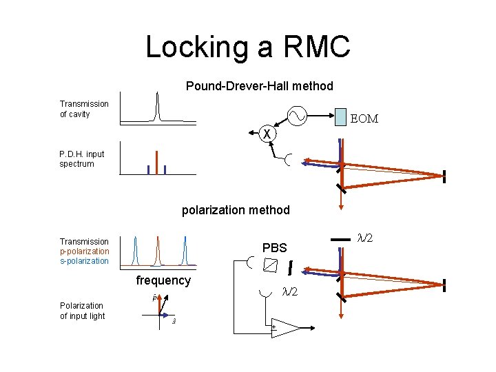
Locking a RMC Pound-Drever-Hall method Transmission of cavity EOM X P. D. H. input spectrum polarization method Transmission p-polarization s-polarization PBS frequency l/2 Polarization of input light l/2 +I
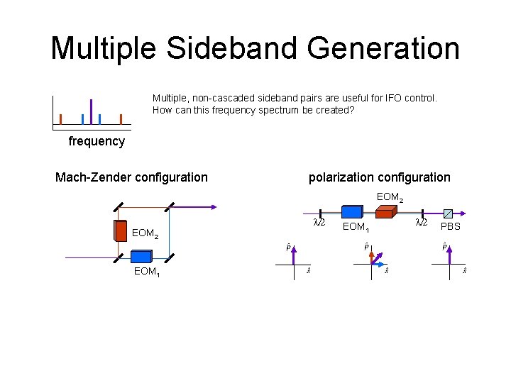
Multiple Sideband Generation Multiple, non-cascaded sideband pairs are useful for IFO control. How can this frequency spectrum be created? frequency Mach-Zender configuration polarization configuration EOM 2 EOM 1 l/2 PBS
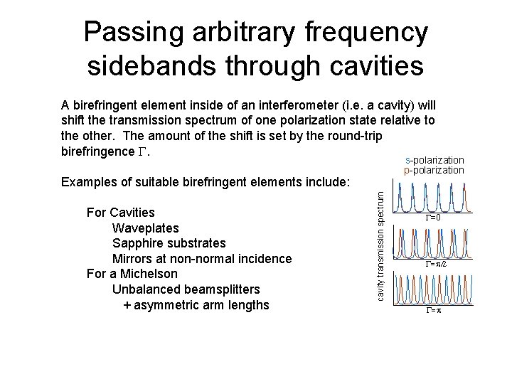
Passing arbitrary frequency sidebands through cavities A birefringent element inside of an interferometer (i. e. a cavity) will shift the transmission spectrum of one polarization state relative to the other. The amount of the shift is set by the round-trip birefringence G. s-polarization p-polarization For Cavities Waveplates Sapphire substrates Mirrors at non-normal incidence For a Michelson Unbalanced beamsplitters + asymmetric arm lengths cavity transmission spectrum Examples of suitable birefringent elements include: G=0 G=p/2 G=p
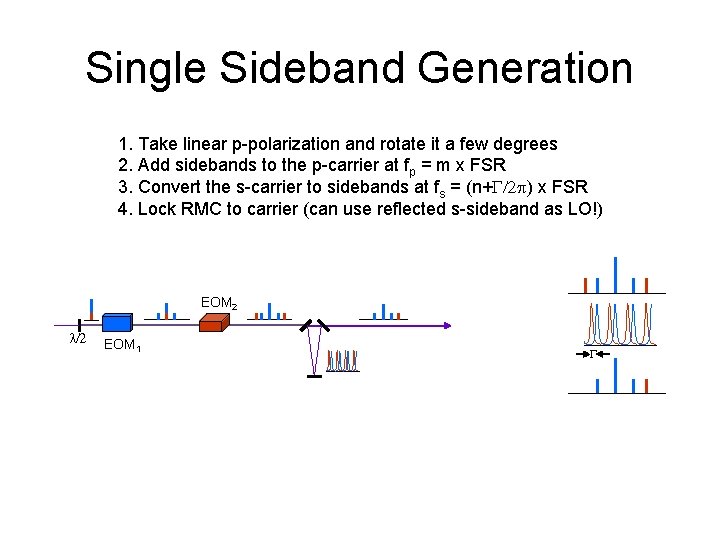
Single Sideband Generation 1. Take linear p-polarization and rotate it a few degrees 2. Add sidebands to the p-carrier at fp = m x FSR 3. Convert the s-carrier to sidebands at fs = (n+G/2 p) x FSR 4. Lock RMC to carrier (can use reflected s-sideband as LO!) EOM 2 l/2 EOM 1 G
My plans for polarization RSE • For current research: Improve control signals of power recycled RSE interferometer at NAOJ by using an orthogonally polarized pair of 2 nd order sidebands. • For fun: Remove SEC degree of freedom by folding SEC onto power recycling cavity.
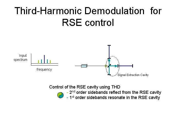
Third-Harmonic Demodulation for RSE control Input spectrum frequency Signal Extraction Cavity Control of the RSE cavity using THD - 2 nd order sidebands reflect from the RSE cavity - 1 st order sidebands resonate in the RSE cavity
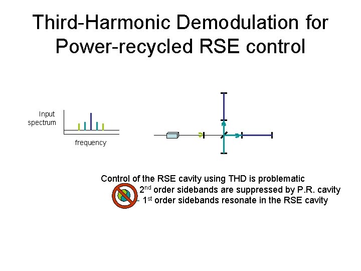
Third-Harmonic Demodulation for Power-recycled RSE control Input spectrum frequency Control of the RSE cavity using THD is problematic 2 nd order sidebands are suppressed by P. R. cavity - 1 st order sidebands resonate in the RSE cavity
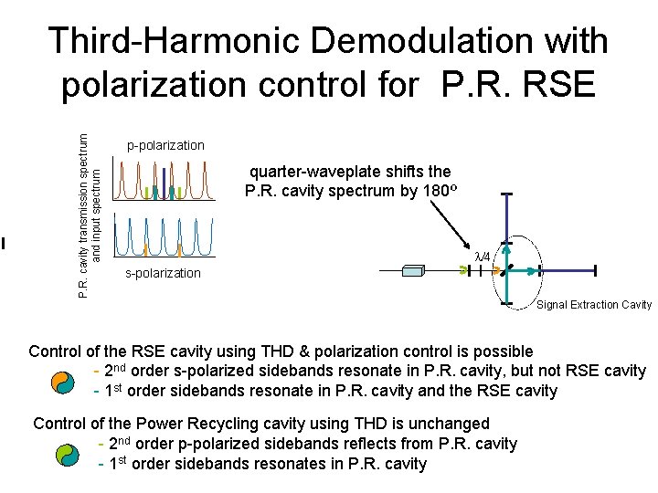
P. R. cavity transmission spectrum and input spectrum Third-Harmonic Demodulation with polarization control for P. R. RSE p-polarization quarter-waveplate shifts the P. R. cavity spectrum by 180º l/4 s-polarization Signal Extraction Cavity Control of the RSE cavity using THD & polarization control is possible - 2 nd order s-polarized sidebands resonate in P. R. cavity, but not RSE cavity - 1 st order sidebands resonate in P. R. cavity and the RSE cavity Control of the Power Recycling cavity using THD is unchanged - 2 nd order p-polarized sidebands reflects from P. R. cavity - 1 st order sidebands resonates in P. R. cavity
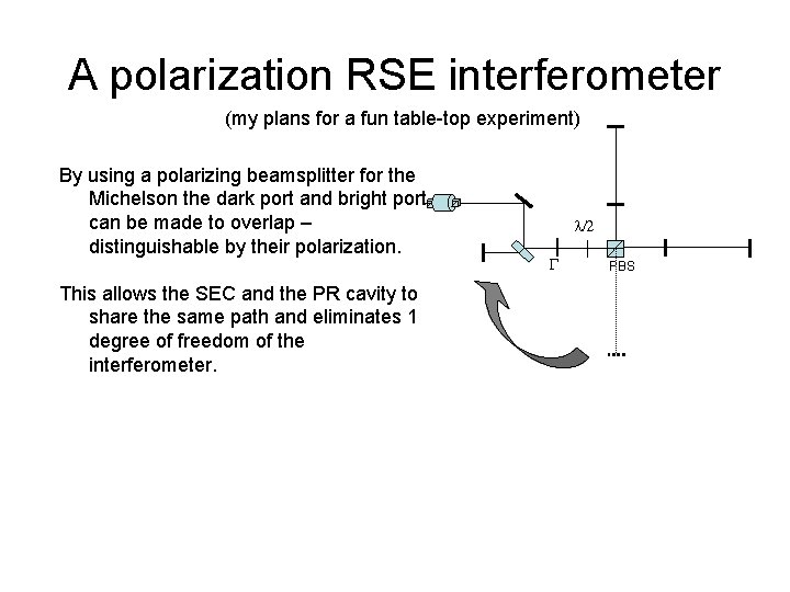
A polarization RSE interferometer (my plans for a fun table-top experiment) By using a polarizing beamsplitter for the Michelson the dark port and bright port can be made to overlap – distinguishable by their polarization. This allows the SEC and the PR cavity to share the same path and eliminates 1 degree of freedom of the interferometer. l/2 G PBS
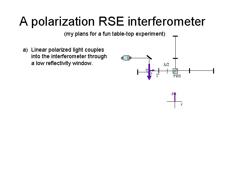
A polarization RSE interferometer (my plans for a fun table-top experiment) a) Linear polarized light couples into the interferometer through a low reflectivity window. l/2 G PBS
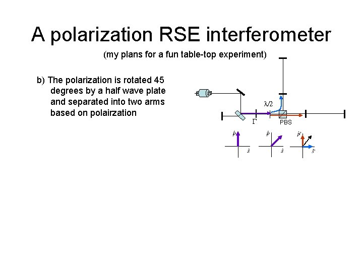
A polarization RSE interferometer (my plans for a fun table-top experiment) b) The polarization is rotated 45 degrees by a half wave plate and separated into two arms based on polairzation l/2 G PBS
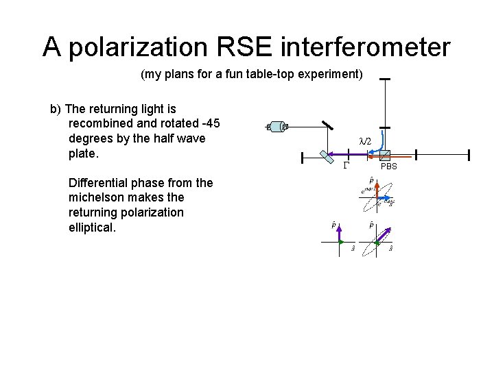
A polarization RSE interferometer (my plans for a fun table-top experiment) b) The returning light is recombined and rotated -45 degrees by the half wave plate. Differential phase from the michelson makes the returning polarization elliptical. l/2 G PBS
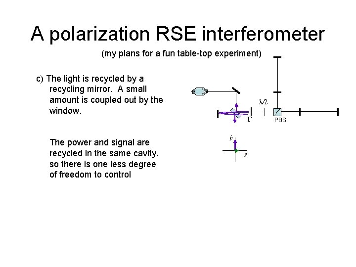
A polarization RSE interferometer (my plans for a fun table-top experiment) c) The light is recycled by a recycling mirror. A small amount is coupled out by the window. The power and signal are recycled in the same cavity, so there is one less degree of freedom to control l/2 G PBS
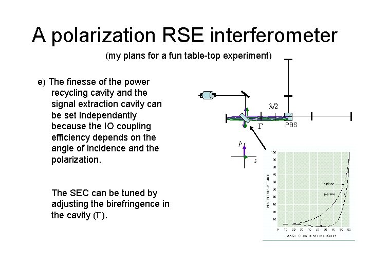
A polarization RSE interferometer (my plans for a fun table-top experiment) e) The finesse of the power recycling cavity and the signal extraction cavity can be set independantly because the IO coupling efficiency depends on the angle of incidence and the polarization. The SEC can be tuned by adjusting the birefringence in the cavity (G). l/2 G PBS
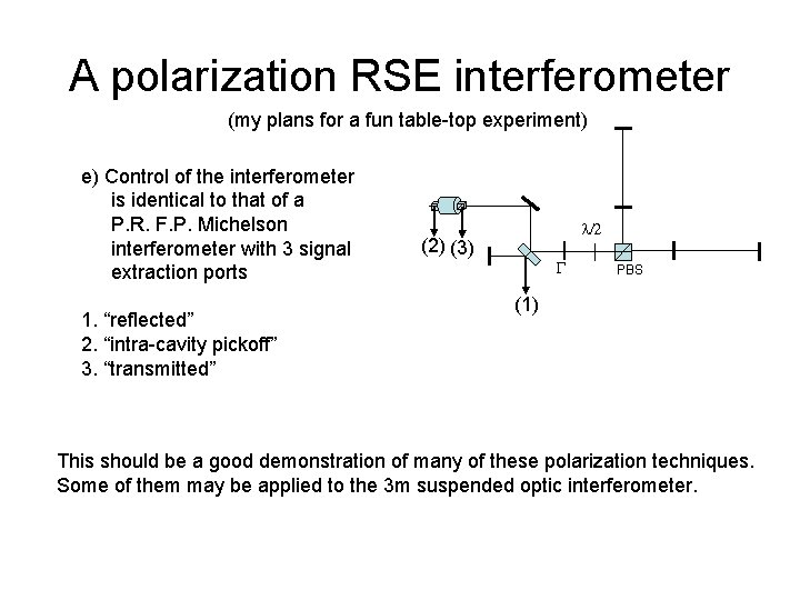
A polarization RSE interferometer (my plans for a fun table-top experiment) e) Control of the interferometer is identical to that of a P. R. F. P. Michelson interferometer with 3 signal extraction ports 1. “reflected” 2. “intra-cavity pickoff” 3. “transmitted” l/2 (2) (3) G PBS (1) This should be a good demonstration of many of these polarization techniques. Some of them may be applied to the 3 m suspended optic interferometer.
Conclusion • Polarization control is 1 more degree of freedom for generating interferometer control signals. • There are useful applications for polarization control in GW interferometry. – Locking cavities – Tuning cavity transmission spectrum – Overlaying beam paths to simplify alignment and control • We plan to use an orthogonally polarized L. O. for the 3 m power recycled RSE interferometer.
- Slides: 26