PLT 328 ROBOTICS CONTROL CHAPTER 5 MOTION CONTROL

PLT 328 ROBOTICS CONTROL CHAPTER 5: MOTION CONTROL

Objectives To determine the types of motion and application of motion control To understand the motion graph operation To understand the relationship between velocity and position profile

Introduction Robot, as well as other multiple joint mechanisms, can be controlled to move in different manners. The different motion types have strong influence in applications in terms of trajectory and cycle time Motion is described in terms of position (x), time (t), velocity (v), and acceleration (a).

Motion types Four different types of controls: 1. limited sequence- each link can only stop at a few limited positions 2. point-to-point (PTP)-each axis or joint has many stoppable positions 3. Continuous- path-several joints can move simultaneously in some user-specified trajectory. 4. intelligent-motions are flexible based on sensors and intelligent to cope with various situations

Motion control applications Industrial robot control Vehicular systems (suspension, brakes, engine control. . . ) Aircraft control and space applications Axis control in various production machines Hydraulic servo, e. g. in forest harvester or excavator Master and slave control in teleoperated systems Mobile robots/machines

Analysis of motion control A robot moves straight up and down. Its height above the ground, as a function of time, is given by the function where t is in seconds and H(t) is in inches. At t = 0, it’s 30 inches above the ground, and after 4 seconds, it’s at height of 18 inches.

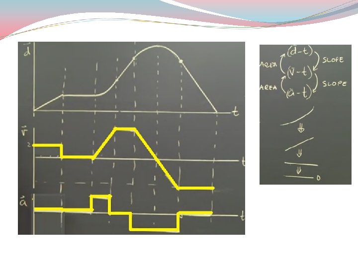
Motion graph
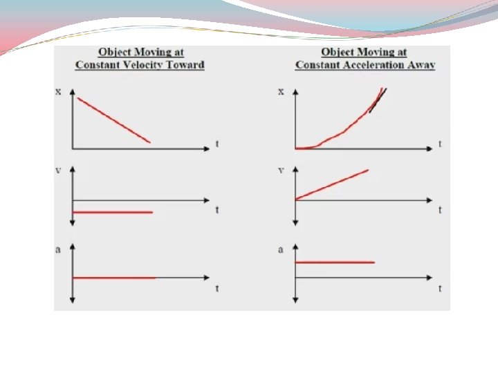
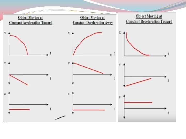

Example With an appropriate diagram, determine the velocity and acceleration based on position in figure
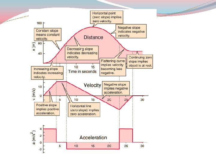
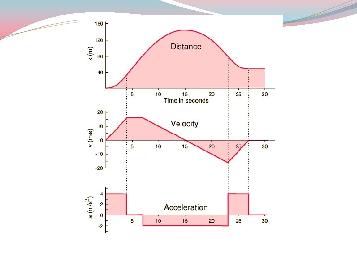

Example With an appropriate diagram, determine the velocity and acceleration based on position in figure

Exercise With an appropriate diagram, determine the velocity and acceleration based on position in figure

Motion profile Velocity profile


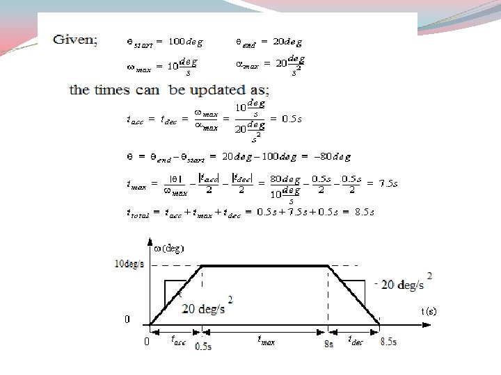
Example Consider a position profile for motion controller. The point-to-point motion in the position profile is designed to move the shaft rotation from θstart = 20° to θend = 100° with the actuator limitation of maximum velocity ωmax = 10°/s and maximum acceleration αmax = 20°/s 2. Design a velocity profile that satifies these constraints.
")
Final Exam (2016/2017)

Answer

Answer

Exercise With an appropriate diagram, determine the velocity and acceleration of a DC motor operation based on position in figure below.
- Slides: 23