PLC Setup Lab Setup Our lab setup consists

PLC Setup

Lab Setup Our lab setup consists of 8 stations each having an IBM-PC compatible computer, 24 VDC power supply and the following PLC hardware • • Power Supply SLC 5/03 CPU DC input card Relay output card

Power Supply PLCs typically include a power supply module in the rack. The power supply only supplies backplane power. This will power the internal electronics of the module. External devices, such as sensors, relays, solenoids must have a different external power source.

CPU front LED will flash when data is being transferred to/from PLC Channel 1 (when used), connects to the data highway Channel 0 connects to IBM-PC serial port

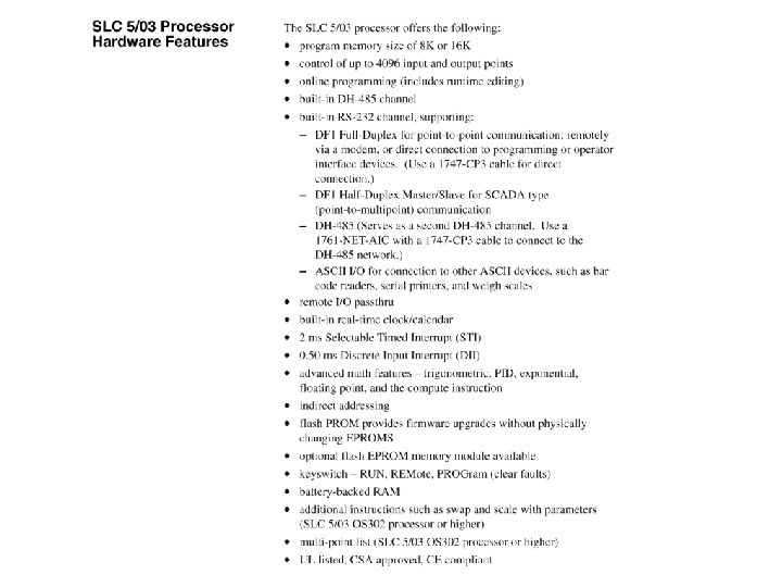
CPU In the Allen-Bradley SLC 500 PLC family there a number of different processors. Each processor will support a core set of instructions and features. However, every processor is different in terms of the advanced instructions that it will support, amount of memory available and speed. Going from least to most powerful the family starts with the SLC 500 (non-modular), 5/01, 5/02, 5/03, 5/04 and 5/05. We have the • SLC 5/03 Processor • 8 K memory • version 3. 02 of firmware

DC input card • 16 point • Uses “sinking” to activate • Each input is activated by bringing the terminal to ground
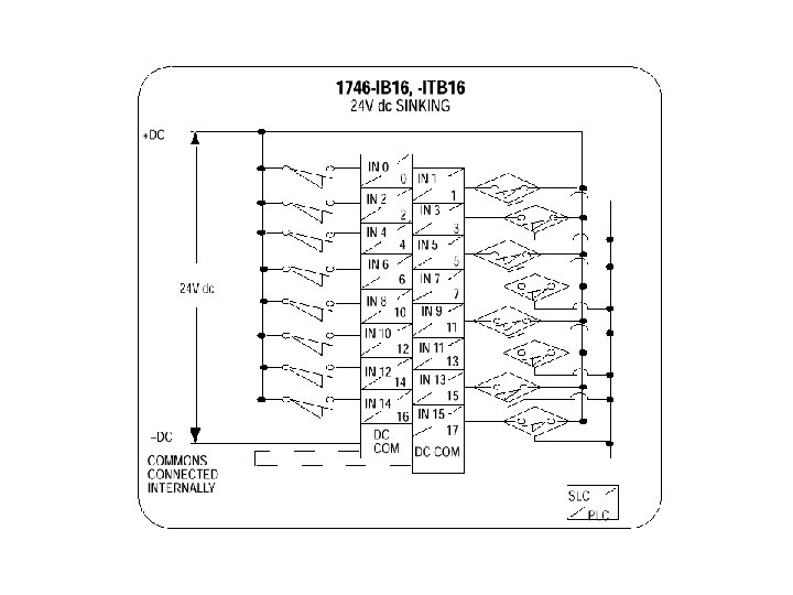

External connections • The PLC power supply doesn't / cannot supply power for the I/O • 24 VDC external supply for the module • Serial cable to PC, COM 1

Connecting outputs

PLC I/O devices • • • Inductive/Capacitive proximity Photoelectric Shaft encoders Relays & Solenoids Mechanical counters

Inductive/Capacitive proximity • Work by using a tuned circuit • Insert RLC diagram here • The circuit is De-tuned by bringing an object near it

Photoelectric • Works by sending and receiving a stream of light pulses • If the stream is interrupted, the sensor activates • Typically operate in the infra-red region • Often have both sink and source outputs

Mechanical counters • Pretty much tamper proof • Slow, 20 -50 m. Sec per increment • Retain display when power is lost/off

PLC Scan

Inputs • All inputs are read at the beginning of the scan • Inputs that change before the next scan are not detected

Description

Logic solved • In the SLC CPUs the placement of rungs within the program does matter

Remote I/O • Communications with the PC • Remote I/O racks • Device Net

Housekeeping • • Updating timers, counters Updating “forces” Diagnostics Watchdog timer – Checks to make sure a scan doesn’t take too long In small programs housekeeping time may account for 90%+ of the scan time.

Outputs • At the end of the scan, the information from the output table is copied to the physical outputs

DH 485

Network communication There are two major protocols for network communication. Token passing and CSMA/CD. Imagine a classroom full of people who would all like to participate in a group discussion. With token passing, someone (maybe the instructor) would start, he/she would be able to talk until they were done. They would then pass the token (in this example the token could be a microphone), to the next person who could then speak. This process continues until everyone has had a chance to talk. If someone has nothing to say, they pass the token on. This approach is also called “Round Robin”.

Token passing

CSMA/CD Instead of using tokens to control who has the right to communicate we could apply the following rules: 1. If no one is speaking, then anyone who wants to can speak. 2. If someone is speaking, then wait 3. If two or more people start to speak at the same time, everyone stops, pauses a random amount of time and try again. CSMA/CD stands for Carrier sense (is anyone speaking), multiple access (many people can use the system) with collision detect (if two people start to speak at the same time, I. e. you hear garbled speech, stop). Ethernet uses this protocol.
- Slides: 25