
Plasma compression of terawatt long wavelength laser pulses

- Slides: 23
Plasma compression of terawatt long wavelength laser pulses Proposal#304309 Funding Status: ONR, Received D. F. Gordon, Y. -H. Chen, L. A. Johnson, P. Grugan, D. Kaganovich, and A. Ting Plasma Physics Division, Naval Research Laboratory M. Babzien, M. N. Polyanskiy, I. V. Pogorelsky, C. Swinson and M. A. Palmer Accelerator Test Facility, Brookhaven National Laboratory *This work is support by Office of Naval Research and Department of Energy
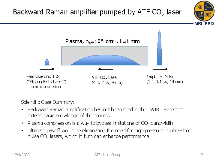
Backward Raman amplifier pumped by ATF CO 2 laser Plasma, ne=1018 cm-3, L=1 mm Femtosecond Ti: S (“Strong Field Laser”) + downconversion ATF CO 2 Laser (4 J, 2 ps, 9 um) Amplified Pulse (1 J, 0. 1 ps, 14 um) Scientific Case Summary: • Backward Raman amplification has not been tried in the LWIR. Expect to extend basic knowledge of the process. • Plasma compression is a way to bypass limitations of CO 2 bandwidth • Ultimate payoff would be eliminating the need for high pressure in ultra-short pulse CO 2 lasers, which in turn can enhance performance. 12/4/2020 ATF Users Group 2
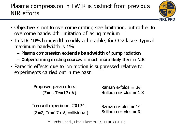
Plasma compression in LWIR is distinct from previous NIR efforts • Objective is not to overcome grating size limitation, but rather to overcome bandwidth limitation of lasing medium • In NIR 10% bandwidth readily achievable, for CO 2 lasers typical maximum bandwidth is 1% – Plasma compression extends bandwidth of pump radiation – Outperforming existing sources is much more likely than in NIR • Parasitic effects due to ion motion is suppressed relative to experiments carried out in the past Proposed parameters: (Z=1, Te=17 e. V) Turnbull experiment 2012*: (Z=2, Te=17 e. V, collisional) Raman e-folds = 36 Brillouin e-folds = 1. 3 Raman e-folds = 10 Brillouin e-folds = 6 * Turnbull et al. , Phys. Plasmas 19, 083109 (2012)
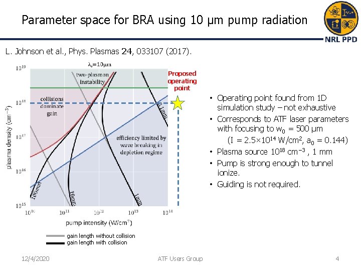
Parameter space for BRA using 10 µm pump radiation L. Johnson et al. , Phys. Plasmas 24, 033107 (2017). Proposed operating point • Operating point found from 1 D simulation study – not exhaustive • Corresponds to ATF laser parameters with focusing to w 0 = 500 μm (I = 2. 5× 10¹⁴ W/cm 2, a 0 = 0. 144) • Plasma source 1018 cm− 3 , 1 mm • Pump is strong enough to tunnel ionize. • Guiding is not required. gain length without collision gain length with collision 12/4/2020 ATF Users Group 4
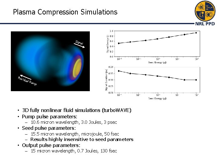
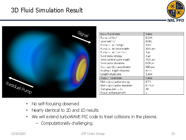
Plasma Compression Simulations Sign al Res idua l Pu mp • 3 D fully nonlinear fluid simulations (turbo. WAVE) • Pump pulse parameters: – 10. 6 micron wavelength, 3. 0 Joules, 3 psec • Seed pulse parameters: – 15. 5 micron wavelength, microjoule, 50 fsec – Results highly insensitive to seed parameters • Output pulse parameters: – 15 micron wavelength, 0. 7 Joules, 130 fsec
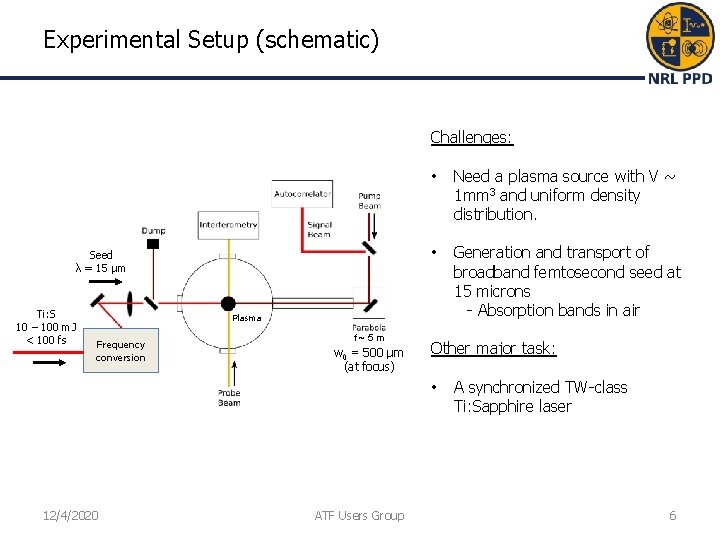
Experimental Setup (schematic) Challenges: Seed λ = 15 μm Ti: S 10 – 100 m. J < 100 fs • Need a plasma source with V ~ 1 mm 3 and uniform density distribution. • Generation and transport of broadband femtosecond seed at 15 microns - Absorption bands in air Plasma Frequency conversion f~5 m w 0 = 500 µm (at focus) Other major task: • 12/4/2020 ATF Users Group A synchronized TW-class Ti: Sapphire laser 6
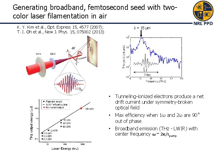
Generating broadband, femtosecond seed with twocolor laser filamentation in air K. Y. Kim et al. , Opt. Express 15, 4577 (2007); T. I. Oh et al. , New J. Phys. 15, 075002 (2013) λ = 15 μm air • Tunneling-ionized electrons produce a net drift current under symmetry-broken optical field • Max efficiency when 1ω and 2ω are 90˚ out of phase • Broadband emission (THz - LWIR) with center frequency ω ~ 2π/τpump
Alternative Seed Generation Methods • OPA and DFG combination – Expensive ~ 100 K, but known reliable method • Optical Rectification – NRL experience, D. F. Gordon, Opt. Expr. 14, 6813 (2006) – Required liquid helium cooled bolometer to see signal (n. J? ) • Use electron beam – Coherent transition radiation, etc. – However, bunch length perhaps too long. 12/4/2020 ATF Users Group 8
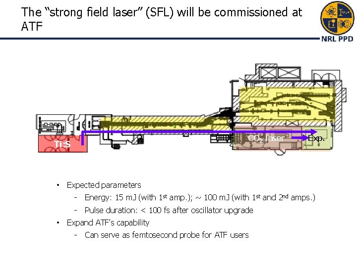
The “strong field laser” (SFL) will be commissioned at ATF CO 2 laser Ti: S • • Expected parameters - Energy: 15 m. J (with 1 st amp. ); ~ 100 m. J (with 1 st and 2 nd amps. ) - Pulse duration: < 100 fs after oscillator upgrade Expand ATF’s capability - Can serve as femtosecond probe for ATF users
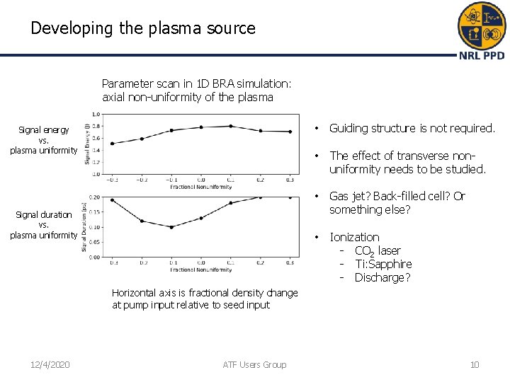
Developing the plasma source Parameter scan in 1 D BRA simulation: axial non-uniformity of the plasma Signal energy vs. plasma uniformity Signal duration vs. plasma uniformity • Guiding structure is not required. • The effect of transverse nonuniformity needs to be studied. • Gas jet? Back-filled cell? Or something else? • Ionization - CO 2 laser - Ti: Sapphire - Discharge? Horizontal axis is fractional density change at pump input relative to seed input 12/4/2020 ATF Users Group 10
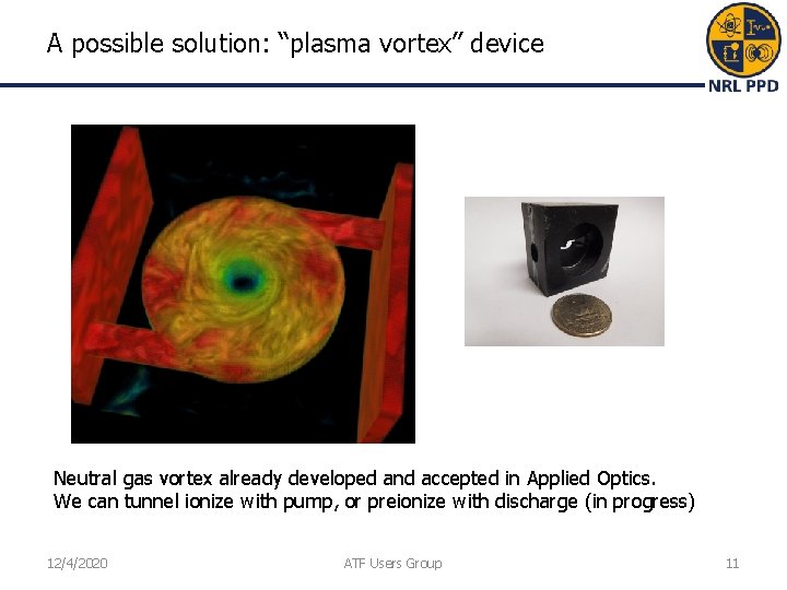
A possible solution: “plasma vortex” device Neutral gas vortex already developed and accepted in Applied Optics. We can tunnel ionize with pump, or preionize with discharge (in progress) 12/4/2020 ATF Users Group 11
Plans: Major Milestones and Timeline (1) • Commisioning of Strong Field Laser (year 1, shared NRL/ATF/…) – Room environment (clean, HVAC) – We are attempting to bring a Navy Vitara-T slave oscillator for at least the duration of the program (3 years), otherwise ~300 hours to setup BNL oscillator – Repair pump lasers, many alignment tasks, etc. (ATF has detailed spreadsheet of tasks and costs) – Route beam to experimental area, synchronize • Develop seed source (underway, year 1) – Use NRL lasers (15 m. J, k. Hz and 2 J, 5 Hz) to pump – Characterize spatial mode (pyrocam, microbolometer) – Characterize spectrum (build LWIR spectrometer) • Develop plasma source (underway, year 1) – Develop gas flow technology, optimize optical properties, discharge 12/4/2020 ATF Users Group 12
Plans: Major Milestones and Timeline (2) • Set up beamlines (year 2, first half) – Build seed generation system at ATF – Long focal length parabola focusing into plasma source – Align and synchronize seed and pump pulses • Observe backward signal (year 2, second half) – Energy, spectrum, pulse length • Characterize parasitic processes and optimize (year 3) – Simulations: collisional PIC, electromagnetic hydro – Comparison of simulated and experimental signal spectra – Characterize transverse signal structure (e. g. , pyrocam), compare with 3 D simulations – Evaluate prospects for higher compression ratios 12/4/2020 ATF Users Group 13
Electron beam requirements • Do not plan to use the e-beam • However, could be used to generate seed pulse based on various radiation processes such as CTR – Back of envelope gives ~100 u. J from 0. 1 n. C at 50 Me. V assuming in coherent regime – Naïve coherence requirements appear unattainable, but more careful analysis might be useful. 12/4/2020 ATF Users Group 14
CO 2 Laser Requirements • Full power configuration is suitable – 4 J, 2 ps, 9. 25 um, M 2 ~ 2, 1 shot per minute • Need much larger f-number final focusing optic – Require ~500 micron spot size – Could investigate IP upstream or downstream of waist, but not ideal • Pointing and timing stability – Prefer ~100 micron accuracy at IP, timing to ~1 ps 12/4/2020 ATF Users Group 15
2019 Experiment Time Estimates • Likely no beam time requested – Developing seed and plasma source at NRL – Repairing Strong Field Laser at ATF – 100% “setup” time • Hazards and Installation – – – Large installation: N Laser use: Y, strong field laser Cryogens: N Introducing new magnetic elements: N Introducing new materials into beam path: N Any other foreseeable beamline modifications: Y (routing SFL to experiment area) 12/4/2020 ATF Users Group 16
Backup Slides 12/4/2020 ATF Users Group 17
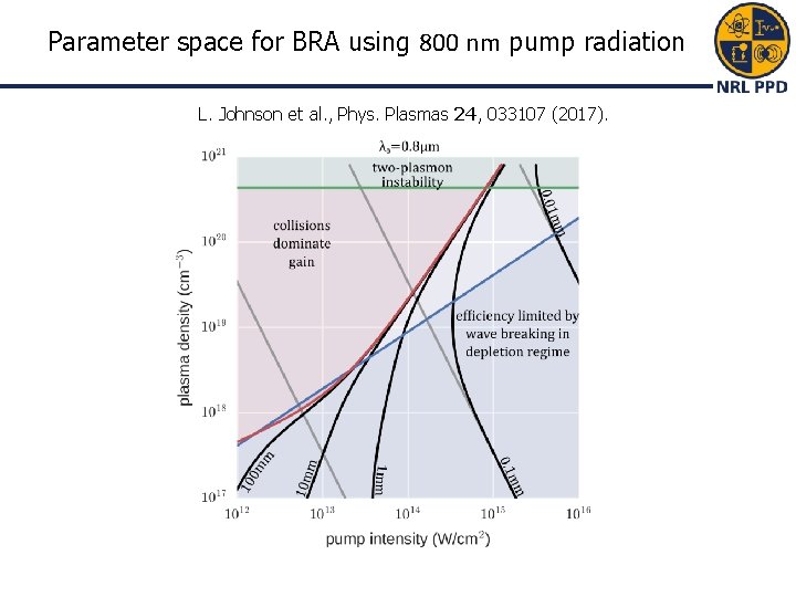
Parameter space for BRA using 800 nm pump radiation L. Johnson et al. , Phys. Plasmas 24, 033107 (2017).
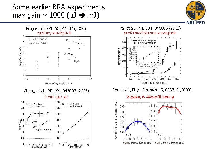
Some earlier BRA experiments max gain ~ 1000 (µJ m. J) Ping et al. , PRE 62, R 4532 (2000) capillary waveguide Cheng et al. , PRL 94, 045003 (2005) 2 mm gas jet Pai et al. , PRL 101, 065005 (2008) preformed plasma waveguide Ren et al. , Phys. Plasmas 15, 056702 (2008) 2 -pass, 6. 4% efficiency
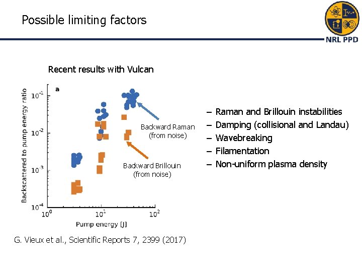
Possible limiting factors Recent results with Vulcan Backward Raman (from noise) Backward Brillouin (from noise) G. Vieux et al. , Scientific Reports 7, 2399 (2017) – – – Raman and Brillouin instabilities Damping (collisional and Landau) Wavebreaking Filamentation Non-uniform plasma density
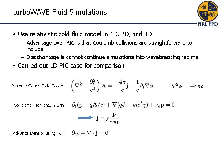
turbo. WAVE Fluid Simulations • Use relativistic cold fluid model in 1 D, 2 D, and 3 D – Advantage over PIC is that Coulomb collisions are straightforward to include – Disadvantage is cannot continue simulations into wavebreaking regime • Carried out 1 D PIC case for comparison Coulomb Gauge Field Solver: Collisional Momentum Eqn: Advance Density using FCT:
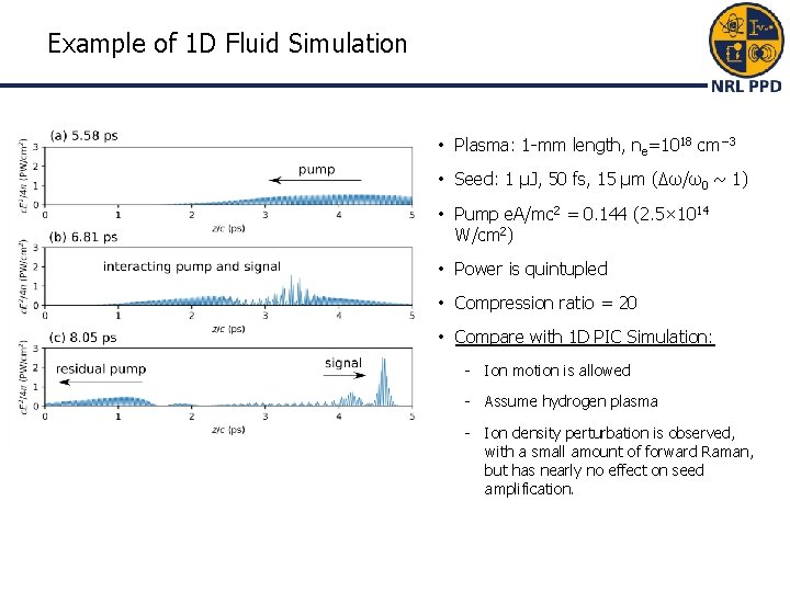
Example of 1 D Fluid Simulation • Plasma: 1 -mm length, ne=1018 cm− 3 • Seed: 1 µJ, 50 fs, 15 µm (Δω/ω0 ~ 1) • Pump e. A/mc 2 = 0. 144 (2. 5× 10¹⁴ W/cm 2) • Power is quintupled • Compression ratio = 20 • Compare with 1 D PIC Simulation: - Ion motion is allowed - Assume hydrogen plasma - Ion density perturbation is observed, with a small amount of forward Raman, but has nearly no effect on seed amplification.
3 D Fluid Simulation Result Sign al Res idua Res l Pu idua al mp l Pu mp • No self-focusing observed • Nearly identical to 2 D and 1 D results • We will extend turbo. WAVE PIC code to treat collisions in the plasma. − Computationally challenging 12/4/2020 ATF Users Group 23